How to Connect and Choose a Flyback Diode for a Relay
9 min
- What Is a Flyback Diode for a Relay?
- How to Connect a Flyback Diode Across a Relay Coil
- Why a Relay Needs a Flyback Diode: Inductive Kickback at Switch-Off
- How to Choose a Flyback Diode for a Relay
- Flyback Diode vs. Zener Clamp for Faster Relay Release
- Conclusion
- FAQs About Flyback Diodes for Relays
Key Takeaways
- Diode Placement: Connect the flyback diode across the relay coil, with its cathode connected to the positive side and its anode to the negative side.
- Why It Matters: When the relay switches off, the diode provides a safe path for the remaining coil current, preventing a high-voltage spike that could damage the transistor.
- Choosing the Right Diode: Select a diode with a reverse-voltage rating above the coil supply voltage and a forward-current rating suitable for the coil current. Common options include the 1N4148W, M7, and SS14, depending on the relay's requirements.
- Faster Relay Release: A standard flyback diode protects the transistor but slows the relay release. Adding a Zener diode in series allows faster release while keeping the voltage within the transistor's safe limits.
A flyback diode for relay coils protects the relay driver when the coil switches off. Without the diode, the coil can generate a high-voltage spike that may damage the transistor. However, diode polarity is critical: installing it backward creates a near short circuit across the power supply when the transistor turns on.
In this guide, you will learn:
- Which way does a flyback diode connect across a relay coil
- What the coil voltage does at switch-off, with and without the diode
- How to choose the diode's reverse-voltage and current ratings
- When a Zener-plus-diode clamp gives a faster relay release
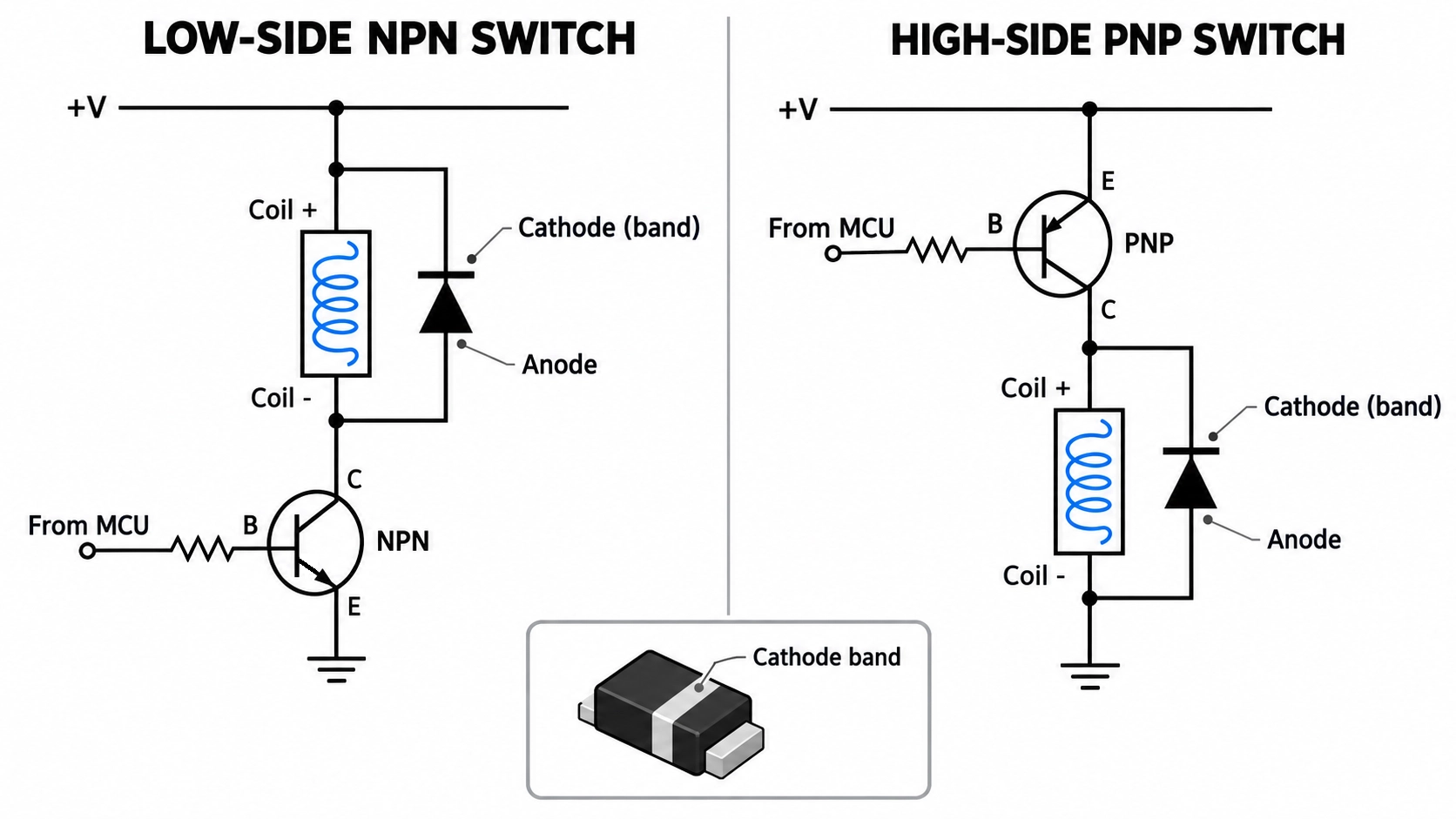
Figure: Flyback diode for relay coils on a low-side NPN switch and a high-side PNP switch
What Is a Flyback Diode for a Relay?
A flyback diode for a relay is a diode connected in parallel with the relay coil that carries the coil current after the drive switch turns off. While the coil is energized, the diode is reverse-biased and conducts no significant current. It is also called a freewheeling diode, a suppression diode, or a catch diode.
On a schematic, the diode sits across the relay coil symbol, with the cathode bar of the diode symbol toward the positive supply. Most relay coils are not polarized, but with the diode fitted, the coil has a fixed polarity.
How to Connect a Flyback Diode Across a Relay Coil
Connect the cathode to the coil terminal that is positive while the relay is energized, and the anode to the other coil terminal. The diode then stays reverse-biased while the relay is on and conducts at switch-off.
For a low-side NPN switch, the steps are:
- Identify the coil ends: Find the coil terminal wired to +V and the one wired to the collector, as in this relay wiring diagram guide.
- Connect the cathode to +V: The cathode is the banded end, as the SMD diode polarity guide shows.
- Connect the anode to the collector: The anode, the coil terminal, and the NPN transistor's collector share a common node.
- Place the diode at the coil: Short traces to the coil pins keep the switch-off current loop small and limit radiated noise.
High-side switching: With a PNP transistor between +V and the coil, the cathode goes to the transistor side of the coil and the anode to ground.
Note
A reversed flyback diode is forward-biased whenever the transistor turns on. It draws high current through the transistor, so the relay does not energize, and the diode or transistor can overheat.
Why a Relay Needs a Flyback Diode: Inductive Kickback at Switch-Off
A relay coil is an inductor, so its current cannot stop instantly when the transistor turns off. The coil voltage reverses to keep that current flowing (V = L·di/dt), and without a current path, the voltage appears across the transistor.
The peak depends on the coil inductance, switching speed, and stray capacitance, so it varies across circuits. It can exceed the transistor's VCEO rating, driving it into breakdown.
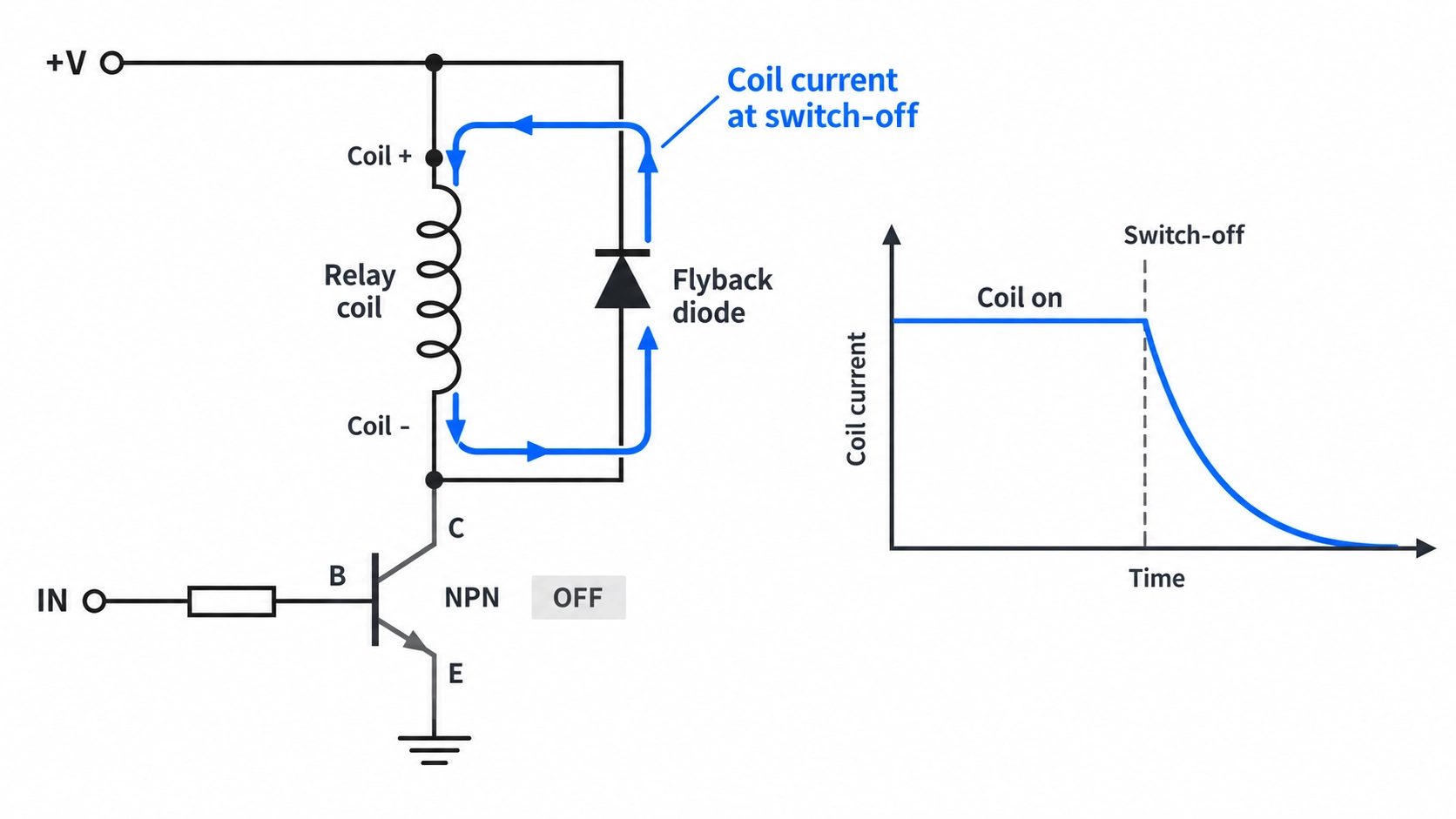
Figure: Switch-off current path of a relay flyback diode, with the coil current circulating through the coil and diode while it decays.
With the diode fitted, the coil current circulates through the coil and diode at switch-off. The collector is held near the supply voltage plus one diode drop, while the coil resistance and diode dissipate the stored energy.
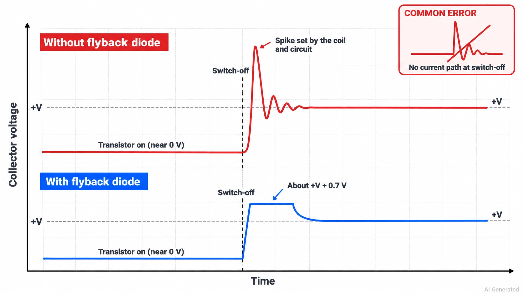
Figure: Collector voltage at relay switch-off without a flyback diode
| Condition | Collector Voltage at Switch-Off | Where the Coil Energy Goes | Risk to the Driver |
|---|---|---|---|
| Without a flyback diode | A spike, set by the coil and circuit | The transistor is in breakdown, and stray capacitance | Transistor overstress or failure, EMI |
| With a flyback diode | About supply + 0.7 V (silicon diode) | Coil resistance and diode | Low, with a correctly rated diode |
How to Choose a Flyback Diode for a Relay
Choose a diode whose reverse-voltage rating is above the coil supply with a margin, and whose forward-current rating is at least the coil current. Because relays switch at low frequency, a standard rectifier is usually fast enough.
- Reverse voltage: Above the coil supply, with margin for supply transients.
- Forward current: At least the coil current, which is the diode's peak current at switch-off.
- Forward voltage: A Schottky diode clamps slightly lower than a silicon diode.
Worked example: A Songle SRD-05VDC-SL-C relay has a 5 V, 70 Ω coil, so the coil current is 5 V / 70 Ω = 71.4 mA. A 75 V, 150 mA diode covers this relay.
The diode types guide explains how switching, rectifier, and Schottky diodes differ. The 1N4148W, M7, and SS14 are all basic parts in the JLCPCB Parts Library:
| Diode | JLCPCB Part | Type and Package | Reverse Voltage | Forward Current | Typical Fit |
|---|---|---|---|---|---|
| 1N4148W | C81598 | Switching, SOD-123 | 75 V | 150 mA | Small relays with coil current well below 150 mA |
| M7 (1N4007 equivalent) | C95872 | Rectifier, SMA | 1000 V | 1 A | General-purpose choice for most relay coils |
| SS14 | C2480 | Schottky, SMA | 40 V | 1 A | Coils up to 24 V, with a lower clamp voltage |
Flyback Diode vs. Zener Clamp for Faster Relay Release
A plain flyback diode protects the transistor but slows the relay's release because the low clamp voltage allows the coil current to decay more slowly. A Zener diode in series raises the clamp voltage, so the current and magnetic field collapse faster.
TE Connectivity's white paper, Coil Suppression Can Reduce Relay Life, reports that slow flux decay reduces the force available to open the armature, so a stuck contact can stay welded closed, and that a diode with a series Zener gives a decay rate close to that of an unsuppressed coil. The trade-off is a higher transistor voltage at switch-off: the supply plus the Zener voltage plus one diode drop.
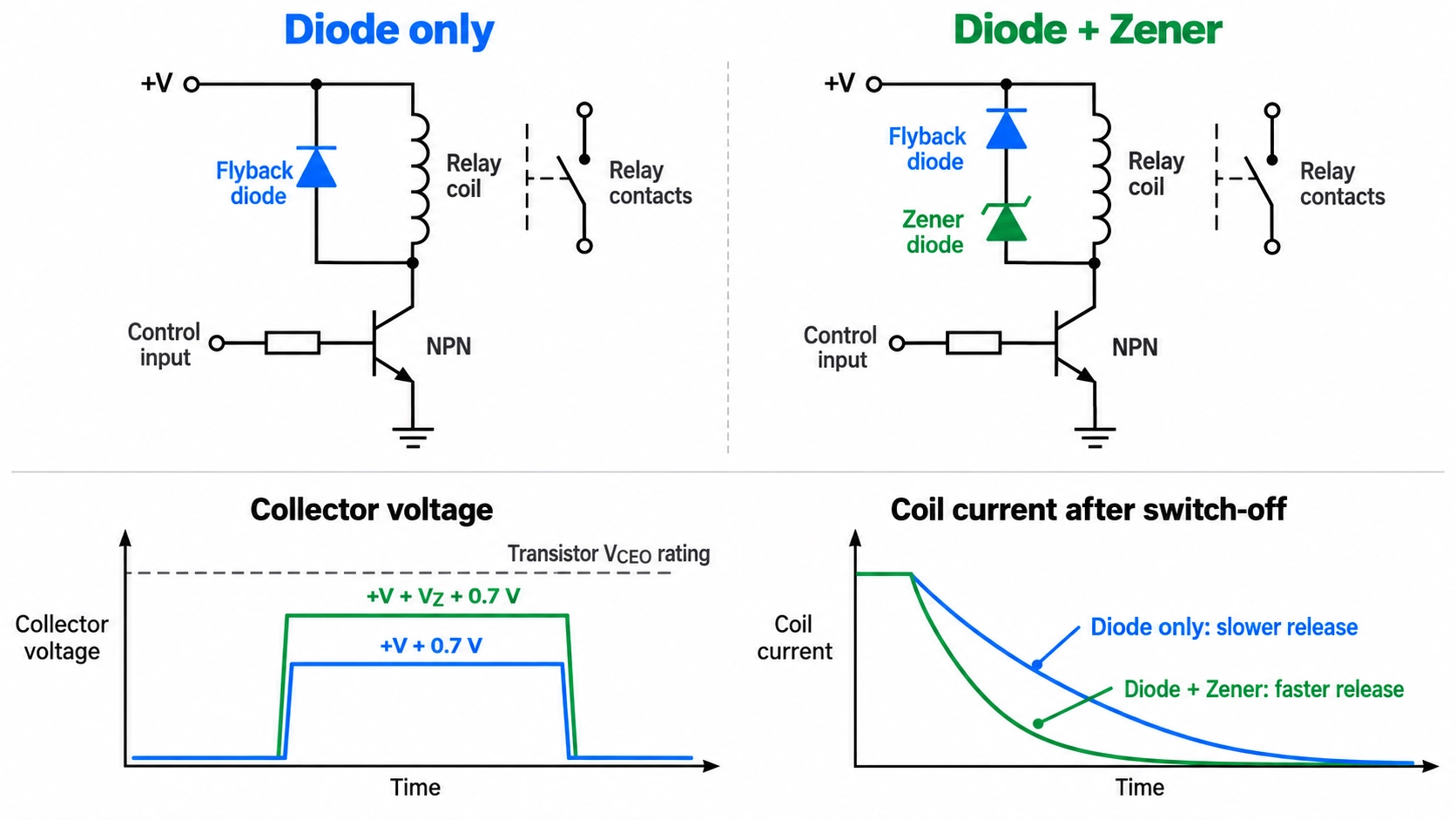
Figure: Diode-only and diode-plus-Zener relay coil suppression, and comparing their clamp voltages.
Worked check: With a 5 V coil, a BZT52C12 12 V Zener (C19077410), and a silicon diode, the collector reaches about 5 + 12 + 0.7 ≈ 17.7 V, or about 18.3 V at the Zener's 12.6 V upper tolerance. These estimates are below the listed 25 V VCEO of C2146, but do not establish worst-case clearance.
Check the selected Zener's maximum voltage at the initial coil current and temperature, the maximum supply, the diode drop, and the switching overshoot before choosing the transistor. If the sum exceeds the transistor's VCEO, choose a lower Zener voltage. The Zener absorbs most of the coil energy, so check its single-pulse thermal/energy capability and its average dissipation at the intended repetition rate.
| Suppression Method | Transistor Voltage at Switch-Off | Release Speed | Coil Type |
|---|---|---|---|
| Diode only | Supply + 0.7 V | Slowest | DC |
| Diode + resistor | Supply + coil current × R + 0.7 V | Faster | DC |
| Diode + Zener | Supply + Zener voltage + 0.7 V | Close to unsuppressed | DC |
| Bidirectional TVS | Supply + TVS clamping voltage | Fast | DC or AC |
| RC snubber | Set by R, C, and the coil current | Moderate | AC or DC |
A flyback diode works on a DC coil only. On an AC coil, it is forward-biased during every half-cycle of one polarity and shorts the supply, so AC coils use an RC snubber, a varistor, or a bidirectional TVS instead.

Once your relay driver circuit is designed and verified, the next step is bringing it to the PCB stage.
Upload your Gerber files to JLCPCB to get an instant manufacturing quote and turn your circuit design into a physical board.
Conclusion
A flyback diode is a simple but essential part of protecting a transistor-driven DC relay. It provides a safe path for the coil current when the relay switches off, preventing damaging voltage spikes.
For reliable protection, connect the diode's cathode to the coil's positive side and choose a diode with appropriate voltage and current ratings. If faster relay release is needed, consider a series Zener diode to balance switching speed and transistor protection.
FAQs About Flyback Diodes for Relays
Do I Need a Flyback Diode for a Relay?
Yes, whenever a transistor, MOSFET, or driver IC switches a DC relay coil. Without one, the switch-off spike can exceed the driver's voltage rating. Many relay modules already include the diode.
What Happens If a Flyback Diode Is Installed Backwards?
The relay does not energize, and the diode or transistor can overheat. The reverse-biased diode conducts as soon as the transistor turns on, drawing high current through the transistor rather than the coil.
Can I Use a 1N4148 as a Relay Flyback Diode?
Yes, for small relays whose coil current is well below the diode's rated forward current, such as a 5 V coil drawing about 71 mA. For larger coils, use a 1 A rectifier such as the 1N4007.
Does a Flyback Diode Slow Down a Relay?
Yes. The diode holds the coil voltage low at switch-off, so the coil current decays slowly and the contacts open later. A Zener in series with the diode shortens the release time.
Can I Use a Schottky Diode as a Relay Flyback Diode?
Yes, when its reverse-voltage rating exceeds the coil supply voltage with a margin. A Schottky, such as the SS14, clamps slightly lower than a silicon diode and is suitable for coils up to 24 V.
Popular Articles
• PCB Silkscreen: All You Need to Know
• The Comprehensive Guide to Circuit Symbols: Key to Understanding Electrical and Electronic Diagrams
• Design Guidelines for PCB Using FR4 Substrates
• Choosing the Best PCB Color-Enhancing Aesthetics and Functionality
• PCB Board Design: A Step-by-Step Guide for Beginners
Keep Learning
Relay Pinout Explained: Diagrams, Pin Functions & Multimeter Testing
Key Takeaways Pin functions: A standard electromechanical relay has two coil pins, and each pole adds a common (COM), normally open (NO), and normally closed (NC) pin. Viewing side: Relay footprints are often drawn in bottom view, with the pins facing you. When a drawing does not state its view, confirm NC and NO with a continuity check. Relay Pin Count: A 5-pin relay is typically SPDT, a 4-pin relay is usually SPST, and an 8-pin relay is commonly DPDT. However, pin arrangements can vary between PCB, ......
How to Connect and Choose a Flyback Diode for a Relay
Key Takeaways Diode Placement: Connect the flyback diode across the relay coil, with its cathode connected to the positive side and its anode to the negative side. Why It Matters: When the relay switches off, the diode provides a safe path for the remaining coil current, preventing a high-voltage spike that could damage the transistor. Choosing the Right Diode: Select a diode with a reverse-voltage rating above the coil supply voltage and a forward-current rating suitable for the coil current. Common ......
A Beginner's Guide to Basic Electronic Components: Functions, Symbols & Uses
Every circuit, from a simple LED flashlight to a microcontroller board, is built from the same handful of common electronic components. This guide breaks down the ten basic electronic components you will encounter most often: What each component does How it works Key specifications Where engineers use it By the end, you will be able to recognize these electronic circuit components on a schematic, a PCB, or a parts bin, and know exactly why each one is there. These electronic components are the buildin......
Reliable BMS Boards Start With Quality PCB Manufacturing
Key Takeaways Dual Duty: BMS PCBs handle heavy currents and millivolt sensing simultaneously, requiring strict layout isolation. Power & Heat: Currents over 10A need 2 oz+ copper pours with via stitching to drop resistance and heat. Clean Sensing: Kelvin differential routing and split grounds prevent load noise from corrupting cell voltage readings. Materials & Finish: High-Tg FR-4 and ENIG surface finishes ensure heat tolerance and flat mounting pads. DFM & Testing: Design for heavy-copper etch toler......
What is Solder Mask and How Does it Impact Your PCB Designs?
Solder mask may not be the most exciting topic in PCB manufacturing, but it's definitely one of the most crucial. Without proper solder mask, your Printed Circuit Boards (PCB's) could suffer from shorts, bridges, corrosion, and other costly and time-consuming issues. So, if you want to ensure the quality, reliability, and longevity of your electronic products, you need to know everything about solder mask - from it's purpose and types to it's application and design implementations. In this ultimate gu......
Understanding Fast Turn PCB: Accelerating Your Electronic Designs
Fast Turn PCB is a quick method to create printed circuit boards (PCBs) to satisfy strict project deadlines. As technology advances so rapidly these days, people more and more desire quicker prototype and computer part manufacturing. Fast Turn PCB services help engineers and designers move quickly from concept to production, which leads to new products in many fields. This article discusses what are Fast Turn PCBs, what they can do for you, and how to choose the best provider to get quality and speed.......