ESP32 Pinout Reference: Which GPIO Pins Are Safe to Use and Avoid?
13 min
- ESP32 Pinout Diagram at a Glance: GPIO Map of the ESP32-WROOM-32E
- ESP32 Pinout: Which GPIO Pins Are Safe to Use?
- Which ESP32 Pins Should You Avoid?
- ESP32 Strapping Pins
- ESP32 Input-Only Pins
- ESP32 ADC Pins: Which Analog Inputs Work with Wi-Fi?
- ESP32 DAC, Touch, and RTC Pins
- ESP32 UART and SPI Pins
- How to Assign ESP32 Pins on Your PCB
- Conclusion
- FAQs About the ESP32 Pinout
Key Takeaways
- GPIO count: The ESP32 chip has 34 GPIOs, and the ESP32-WROOM-32E module exposes 26 of them.
- General-purpose pins: Fifteen module GPIOs carry no boot, flash, or input-only restrictions: GPIO4, GPIO13, GPIO14, GPIO16 to GPIO19, GPIO21 to GPIO23, GPIO25 to GPIO27, GPIO32, and GPIO33.
- Strapping pins: GPIO0, GPIO2, GPIO5, GPIO12, and GPIO15 are sampled at reset, so any circuit connected to them must maintain the level required by the boot mode.
- Input-only pins: GPIO34, GPIO35, GPIO36, and GPIO39 have no output driver and no internal pull-up or pull-down resistors.
- ADC2 and Wi-Fi: ADC2 is shared with the Wi-Fi driver, so analog inputs read while Wi-Fi is active should use ADC1 pins.
Most pins in the ESP32 pinout are general-purpose I/O, but four groups need care: flash pins, strapping pins, input-only pins, and ADC2 pins. Choosing the wrong GPIO pins can cause boot failures or inaccurate ADC readings when Wi-Fi is enabled.
In this guide, you will learn:
- Which ESP32-WROOM-32E pins are free to use for each type of signal
- Which pins to avoid, and why
- How strapping pins, input-only pins, and ADC2 pins behave
- Which pins carry the DAC, touch, deep-sleep wake-up, UART, SPI, and I2C functions
- How to assign ESP32 pins when you design your own PCB
Note
This guide specifically uses the ESP32-WROOM-32E as the pinout reference. Pin mappings differ across ESP32 variants such as the ESP32-S2, ESP32-C3, and ESP32-S3, so check the corresponding variant-specific pinout when using another device.
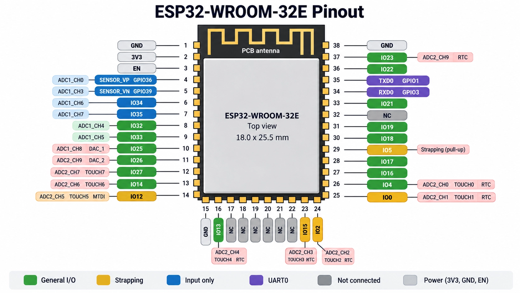
Figure: ESP32 pinout of the ESP32-WROOM-32E module
ESP32 Pinout Diagram at a Glance: GPIO Map of the ESP32-WROOM-32E
The ESP32 chip has 34 GPIOs. The ESP32-WROOM-32E module, built on the ESP32-D0WD-V3, brings out 26 of them on its 38 pins.
The remaining eight are not available: GPIO6 to GPIO11 connect to the module's SPI flash, and GPIO37 and GPIO38 are not led out.
| GPIO | Module Pin | Pin Type | ADC or DAC | Notes |
|---|---|---|---|---|
| GPIO0 | 25 | Strapping | ADC2_CH1 | Low at reset, with GPIO2 low, enters serial download mode |
| GPIO1 | 35 (TXD0) | UART0 | None | Programming and boot log output |
| GPIO2 | 24 | Strapping | ADC2_CH2 | Low or floating to enter download mode |
| GPIO3 | 34 (RXD0) | UART0 | None | Programming input |
| GPIO4 | 26 | General I/O | ADC2_CH0 | None |
| GPIO5 | 29 | Strapping | None | Default VSPI chip select |
| GPIO6 to GPIO11 | Not led out | Flash | None | Connected to the module's SPI flash |
| GPIO12 | 14 | Strapping | ADC2_CH5 | Keep low at power-on; JTAG MTDI |
| GPIO13 | 16 | General I/O | ADC2_CH4 | JTAG MTCK |
| GPIO14 | 13 | General I/O | ADC2_CH6 | JTAG MTMS |
| GPIO15 | 23 | Strapping | ADC2_CH3 | Low at reset silences the boot log; JTAG MTDO |
| GPIO16 | 27 | General I/O | None | Used by the PSRAM on the R2 module variants |
| GPIO17 | 28 | General I/O | None | None |
| GPIO18 | 30 | General I/O | None | Default VSPI clock |
| GPIO19 | 31 | General I/O | None | Default VSPI MISO |
| GPIO21 | 33 | General I/O | None | Arduino default I2C SDA |
| GPIO22 | 36 | General I/O | None | Arduino default I2C SCL |
| GPIO23 | 37 | General I/O | None | Default VSPI MOSI |
| GPIO25 | 10 | General I/O | ADC2_CH8, DAC_1 | None |
| GPIO26 | 11 | General I/O | ADC2_CH9, DAC_2 | None |
| GPIO27 | 12 | General I/O | ADC2_CH7 | None |
| GPIO32 | 8 | General I/O | ADC1_CH4 | 32.768 kHz crystal input |
| GPIO33 | 9 | General I/O | ADC1_CH5 | 32.768 kHz crystal output |
| GPIO34 | 6 | Input only | ADC1_CH6 | No internal pull resistors |
| GPIO35 | 7 | Input only | ADC1_CH7 | No internal pull resistors |
| GPIO36 | 4 (SENSOR_VP) | Input only | ADC1_CH0 | No internal pull resistors |
| GPIO37, GPIO38 | Not led out | Input only | ADC1_CH1, ADC1_CH2 | Not available on the module |
| GPIO39 | 5 (SENSOR_VN) | Input only | ADC1_CH3 | No internal pull resistors |
Note
This pinout applies to the original ESP32. The ESP32-S2, ESP32-C3 and ESP32-S3, as well as other series, use different GPIO numbers, strapping pins, and ADC channels, so check the datasheet for the exact chip.
ESP32 Pinout: Which GPIO Pins Are Safe to Use?
On the ESP32-WROOM-32E, 15 GPIOs carry no boot, flash, or input-only restriction: GPIO4, GPIO13, GPIO14, GPIO16 to GPIO19, GPIO21 to GPIO23, GPIO25 to GPIO27, GPIO32, and GPIO33.
A few of these have conditions:
- GPIO4, GPIO13, GPIO14, and GPIO25 to GPIO27: These are ADC2 pins. Their digital function works with Wi-Fi active; only their analog input is shared.
- GPIO13 and GPIO14: These carry the JTAG signals MTCK and MTMS. Keep them free if you debug over JTAG.
- GPIO16: On -R2 module variants with 2 MB of PSRAM (pseudo-static RAM), this pin connects to the PSRAM and cannot be used for other functions.
- GPIO32 and GPIO33: These connect to the optional 32.768 kHz crystal. Use them as GPIOs only when no crystal is fitted.
The right pin depends on the signal:
| Signal | Use These Pins |
|---|---|
| Digital output, such as an LED, relay driver, or chip select | GPIO4, GPIO13, GPIO14, GPIO16 to GPIO19, GPIO21 to GPIO23, GPIO25 to GPIO27, GPIO32, GPIO33 |
| Digital input that needs an internal pull-up or pull-down | Any general I/O pin |
| Digital input with an external pull resistor | GPIO34, GPIO35, GPIO36, GPIO39 |
| Analog input read while Wi-Fi is active | ADC1: GPIO32 to GPIO36, GPIO39 |
| Analog output | DAC: GPIO25, GPIO26 |
| High-speed SPI | VSPI IO MUX pins: GPIO5, GPIO18, GPIO19, GPIO23 |
Which ESP32 Pins Should You Avoid?
Avoid GPIO6-GPIO11 entirely, and use the strapping, input-only, UART0, and ADC2 pins only within their limits.
| Pin Group | Pins | Restriction | What to Do |
|---|---|---|---|
| Flash | GPIO6 to GPIO11 | Connected to the SPI flash | Leave unconnected |
| Strapping | GPIO0, GPIO2, GPIO5, GPIO12, GPIO15 | Sampled at reset to set the boot configuration | Keep the required level during reset |
| Input only | GPIO34, GPIO35, GPIO36, GPIO39 | No output driver, no internal pull resistors | Use for inputs with an external pull resistor |
| UART0 | GPIO1, GPIO3 | Used for firmware download and the boot log | Keep for programming and debugging |
| ADC2 | GPIO0, GPIO2, GPIO4, GPIO12 to GPIO15, GPIO25 to GPIO27 | ADC shared with the Wi-Fi driver | Use ADC1 for analog inputs read with Wi-Fi on |
| PSRAM | GPIO16 on -R2 variants | Connected to the in-package PSRAM | Leave unconnected on those variants |
ESP32 Strapping Pins
Strapping pins are sampled during reset to determine settings such as boot mode, flash supply voltage, and boot logging. Once the reset is complete, they can be used as normal GPIOs.
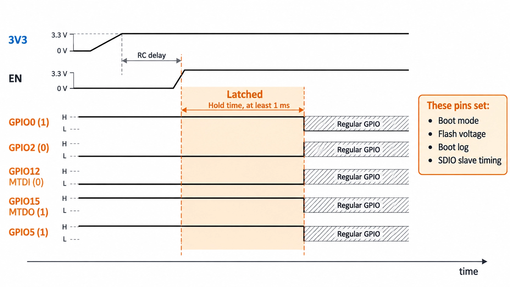
Figure: ESP32 strapping pin levels latched at reset, then released as regular GPIOs.
The chip latches their levels at reset and holds them until power-down. The datasheet requires the levels to be held for at least 1 ms after EN goes high. With nothing connected, internal weak pull resistors set the default level.
| Strapping Pin | Internal Default | What It Sets at Reset | Required Level for Normal Boot |
|---|---|---|---|
| GPIO0 | Pull-up (1) | Boot mode: 1 boots from flash; 0, with GPIO2 low, enters download mode | High |
| GPIO2 | Pull-down (0) | Boot mode, together with GPIO0 | Any level, low or floating for download mode |
| GPIO12 (MTDI) | Pull-down (0) | Flash voltage (VDD_SDIO): 0 selects 3.3 V, 1 selects 1.8 V | Low |
| GPIO15 (MTDO) | Pull-up (1) | Boot log on UART0, and SDIO slave timing | High keeps the log; low silences it |
| GPIO5 | Pull-up (1) | SDIO slave timing, together with GPIO15 | Default level, unless the ESP32 runs as an SDIO slave device |
If GPIO12 is high at reset, VDD_SDIO switches to the internal 1.8 V low-dropout regulator (LDO), and the module typically fails to boot. The module datasheet states that IO12 should be kept low at power-on.
If a circuit must hold GPIO12 high at reset, the flash voltage can instead be fixed at 3.3 V in eFuse, which frees GPIO12 but cannot be reversed.
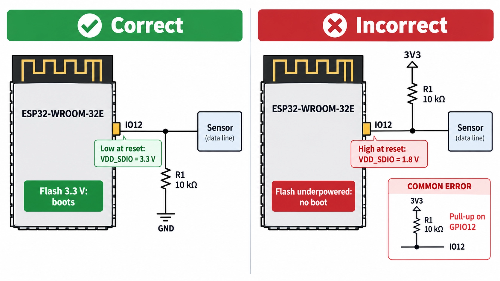
Figure: A pull-up that selects 1.8 V flash voltage at reset.
To use a strapping pin safely:
- Match the default level: Connect loads that do not override the internal default during reset, such as a chip-select line that idles high on GPIO5.
- Use external resistors to change a level: The internal pull resistors are typically 45 kω, so an external pull resistor provides more reliable level control.
- Avoid pull-ups on GPIO12: A sensor module or level shifter with its own pull-up on this pin can hold it high at reset.
ESP32 Input-Only Pins
GPIO34, GPIO35, GPIO36, and GPIO39 can read signals but cannot drive an output. These pins have no output driver and no internal pull-up or pull-down circuitry.
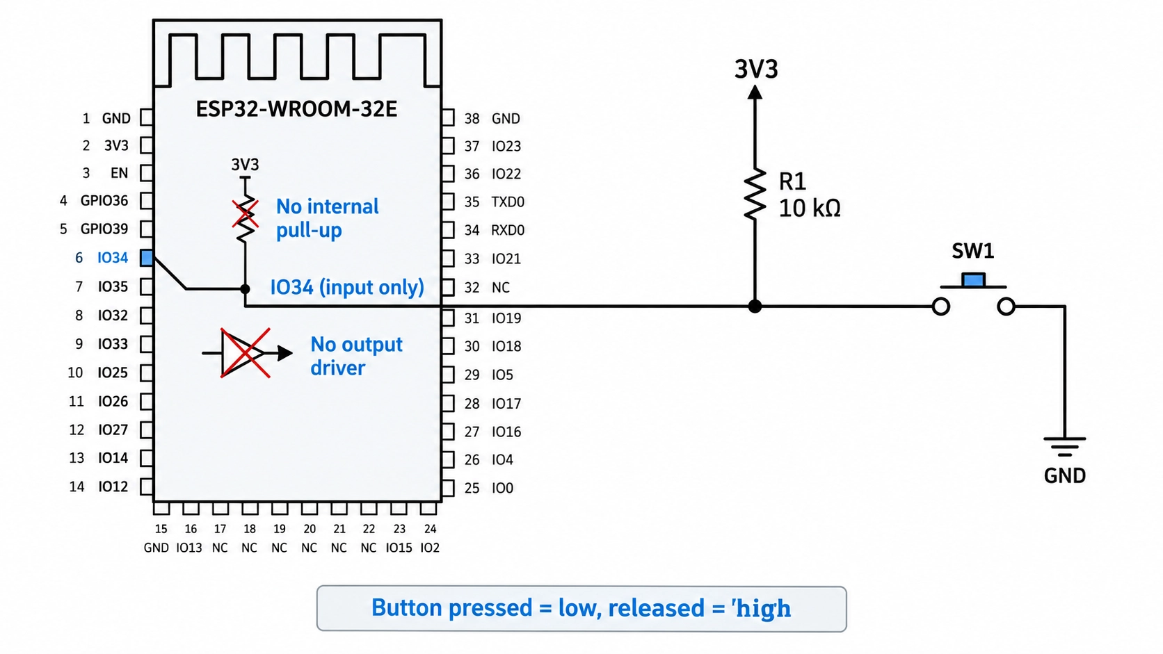
Figure: Push button on GPIO34 with an external 10 kΩ pull-up resistor to 3.3 V.
They suit analog inputs and digital inputs with an external bias:
- Buttons and switches: Add an external pull-up or pull-down resistor, typically 10 kω, to prevent the input from floating.
- Analog sensors: All four are ADC1 channels, so they keep working while Wi-Fi is active.
- Interrupts on GPIO36 and GPIO39: ESP-IDF advises against using these interrupts when the ADC, Wi-Fi, or Bluetooth are in use with sleep mode enabled.
ESP32 ADC Pins: Which Analog Inputs Work with Wi-Fi?
Use ADC1 for analog inputs that are read while Wi-Fi is active.
The Wi-Fi driver also uses ADC2, so an ADC2 read can fail while the Wi-Fi driver is using ADC2. The ESP32 has two 12-bit SAR (successive-approximation register) ADCs with 18 channels. On the WROOM-32E, 16 of them are available.
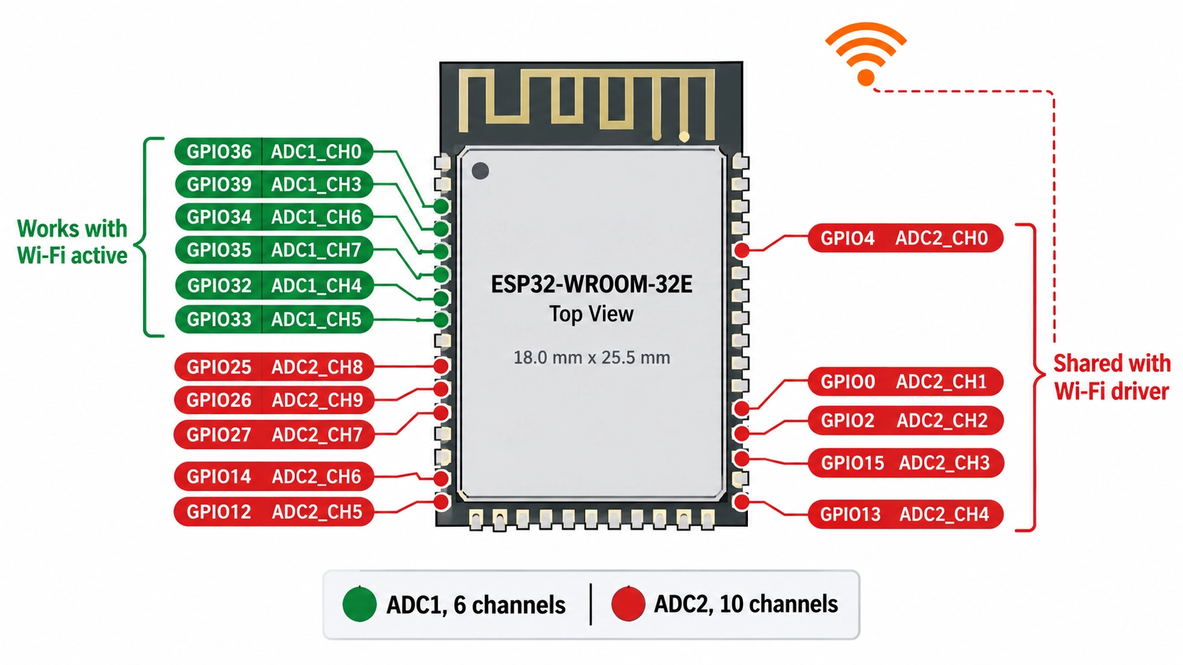
Figure: ESP32 ADC1 and ADC2 pin map
| Property | ADC1 | ADC2 |
|---|---|---|
| Module pins | GPIO32 to GPIO36, GPIO39 | GPIO0, GPIO2, GPIO4, GPIO12 to GPIO15, GPIO25 to GPIO27 |
| Channels on the module | 6 | 10 |
| Works while Wi-Fi is active | Yes | Not reliably |
| Shares pins with strapping | No | Yes: GPIO0, GPIO2, GPIO12, GPIO15 |
ESP32 DAC, Touch, and RTC Pins
The DAC, touch, and RTC functions are fixed to specific pins. Unlike UART or I2C, they cannot be moved to another GPIO.
ESP32 DAC Pins
The ESP32 has two 8-bit DAC channels: DAC_1 on GPIO25 and DAC_2 on GPIO26. They suit audio tones, bias voltages, and slow analog control signals.
ESP32 Touch Pins
Ten GPIOs support capacitive touch sensing:
| Touch Channel | GPIO | Touch Channel | GPIO |
|---|---|---|---|
| TOUCH0 | GPIO4 | TOUCH5 | GPIO12 |
| TOUCH1 | GPIO0 | TOUCH6 | GPIO14 |
| TOUCH2 | GPIO2 | TOUCH7 | GPIO27 |
| TOUCH3 | GPIO15 | TOUCH8 | GPIO33 |
| TOUCH4 | GPIO13 | TOUCH9 | GPIO32 |
Four touch pins are also strapping pins: Prefer GPIO4, GPIO13, GPIO14, GPIO27, GPIO32, and GPIO33 for touch pads, using GPIO32 and GPIO33 only when no 32.768 kHz crystal is fitted.
ESP32 RTC Pins
The ESP32 has 16 RTC-capable GPIOs: GPIO0, GPIO2, GPIO4, GPIO12–15, GPIO25–27, GPIO32–36, and GPIO39. These pins connect to the RTC subsystem and can wake the ESP32 from deep sleep when triggered by an external signal. This makes them useful for low-power applications such as battery-powered sensors, wake-up buttons, and monitoring circuits.
ESP32 UART and SPI Pins
For most digital peripherals, the ESP32 offers flexible GPIO assignment through its internal GPIO matrix. This signal-routing system can connect UART, SPI, I2C, I2S, and PWM signals to different GPIO pins. However, output signals require output-capable pins, so GPIO34–GPIO39 cannot be used for peripheral outputs.
ESP32 UART Pins
The ESP32 has three UARTs. UART0 uses GPIO1 (TX) and GPIO3 (RX) for programming and the boot log. UART2's IO MUX pins, the fixed pins that bypass the GPIO matrix, are GPIO16 (RX) and GPIO17 (TX). UART1's IO MUX pins are GPIO9 (RX) and GPIO10 (TX), which are flash pins, so route UART1 to other GPIOs through the GPIO matrix.
ESP32 SPI Pins
SPI signals can use any GPIO, but the IO MUX pins, which connect each SPI controller directly to fixed pins, support higher clock rates. ESP-IDF lists up to 80 MHz on the IO MUX pins. Through the GPIO matrix, full-duplex transfers are limited to about 26 MHz.
| SPI Signal | SPI2 (HSPI) | SPI3 (VSPI) |
|---|---|---|
| CS0 | GPIO15 | GPIO5 |
| SCLK | GPIO14 | GPIO18 |
| MISO | GPIO12 | GPIO19 |
| MOSI | GPIO13 | GPIO23 |
How to Assign ESP32 Pins on Your PCB
Assign the fixed functions first and the flexible ones last. This order keeps boot-critical and analog pins free before general digital signals claim them.
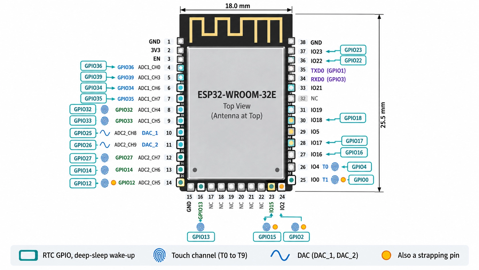
Figure: Pinout of ESP32-WROOM-32E with pin functions
- Power and programming: 3V3, GND, EN, GPIO0, GPIO1 (TX), and GPIO3 (RX).
- Analog inputs: ADC1 pins for anything read while Wi-Fi is active.
- Fixed-function pins: DAC, touch, and the 32.768 kHz crystal, if used.
- High-speed SPI: The VSPI IO MUX pins.
- Other digital signals: The remaining general I/O pins.
- Strapping pins last: Only for signals whose reset state matches the default level.
Conclusion
Most of the ESP32 pinout is general-purpose I/O, but the flash, strapping, input-only, and ADC2 pins each have restrictions. Leave GPIO6 to GPIO11 unconnected, keep strapping pins at their required levels during reset, use GPIO34, GPIO35, GPIO36, and GPIO39 as inputs, and put analog inputs on ADC1 when Wi-Fi is active.
Assigning pins this way helps the board boot reliably and avoids a respin caused by a pin conflict.
Once your design is ready, upload your files to JLCPCB to review assembly options and get an instant quote.
FAQs About the ESP32 Pinout
How Many GPIO Pins Does the ESP32 Have?
The ESP32 chip has 34 GPIOs. The ESP32-WROOM-32E module brings out 26, because GPIO6 to GPIO11 connect to its flash, and GPIO37 and GPIO38 are not led out.
Are ESP32 GPIO Pins 5 V Tolerant?
No. The datasheet limits the high-level input voltage to VDD + 0.3 V, which is 3.6 V on a 3.3 V supply. Use a level shifter for 5 V signals.
How Much Current Can an ESP32 GPIO Pin Source or Sink?
ESP32 GPIOs can source or sink tens of milliamps, but the datasheet’s maximum figure of about 40 mA per pin at the highest drive strength is not a recommended continuous operating current.
For reliable designs, keep the GPIO current well below the maximum and check the voltage and current conditions in the datasheet. For LEDs, relays, motors, or other higher-current loads, use a transistor, MOSFET, or dedicated driver instead of driving the load directly from the GPIO.
Can I Use the ESP32 TX and RX Pins as GPIO?
Yes, after boot, but GPIO1 and GPIO3 form UART0, which carries firmware download and the boot log. Other signals on these pins can interfere with programming.
Is the ESP32-S3 Pinout the Same as the ESP32 Pinout?
No. The ESP32-S3 has 45 GPIOs and different strapping pins: GPIO0, GPIO3, GPIO45, and GPIO46. Check its own datasheet before reusing an ESP32 pin assignment.
Popular Articles
• PCB Silkscreen: All You Need to Know
• The Comprehensive Guide to Circuit Symbols: Key to Understanding Electrical and Electronic Diagrams
• Design Guidelines for PCB Using FR4 Substrates
• Choosing the Best PCB Color-Enhancing Aesthetics and Functionality
• PCB Board Design: A Step-by-Step Guide for Beginners
Keep Learning
ESP32 Pinout Reference: Which GPIO Pins Are Safe to Use and Avoid?
Key Takeaways GPIO count: The ESP32 chip has 34 GPIOs, and the ESP32-WROOM-32E module exposes 26 of them. General-purpose pins: Fifteen module GPIOs carry no boot, flash, or input-only restrictions: GPIO4, GPIO13, GPIO14, GPIO16 to GPIO19, GPIO21 to GPIO23, GPIO25 to GPIO27, GPIO32, and GPIO33. Strapping pins: GPIO0, GPIO2, GPIO5, GPIO12, and GPIO15 are sampled at reset, so any circuit connected to them must maintain the level required by the boot mode. Input-only pins: GPIO34, GPIO35, GPIO36, and GPI......
PCB Silkscreen: All You Need to Know
Key Takeaways The PCB Silkscreen Guide demonstrates that a properly designed legend layer is essential to prevent assembly failures and ensure long-term hardware reliability. By mastering modern manufacturing methodologies like Direct Legend Printing (DLP) and aligning layouts with JLCPCB's strict DFM design rules—including the absolute 0.8 mm character height limit and the automated 0.15 mm silkscreen clipping protocol driven by solder mask precedence—engineers can seamlessly eliminate cold joints an......
A Beginner's Guide to Basic Electronic Components: Functions, Symbols & Uses
Every circuit, from a simple LED flashlight to a microcontroller board, is built from the same handful of common electronic components. This guide breaks down the ten basic electronic components you will encounter most often: What each component does How it works Key specifications Where engineers use it By the end, you will be able to recognize these electronic circuit components on a schematic, a PCB, or a parts bin, and know exactly why each one is there. These electronic components are the buildin......
How to Read and Create PCB Schematics
Key Takeaways Read Schematics: Understand symbols, net labels, and component values. Design in EasyEDA: Place components and create circuit connections. Run Design Checks: Use ERC and DRC to identify potential issues. Verify Components: Check pin assignments and PCB footprints. Prepare for Manufacturing: Validate PCB layouts and manufacturing files. Printed circuit board (PCB) design begins with a clear understanding of how the electronic circuit should function. A schematic diagram represents the cir......
Maximizing Circuit Reliability with PCB Test Points and Smart DFT
Key Takeaways Early Fault Catching: Test points drastically reduce diagnosis time and prevent costly field failures. Standard Pad Sizing: Use 1.0 mm flat copper pads with 2.54 mm spacing for optimal fixture contact. Protect High-Speed Signals: Keep branch traces short to prevent capacitive loading and resonance. Single-Sided Access: Place all test pads on the bottom layer to cut fixture costs. Right Test for Volume: Use flying probe for prototypes and bed-of-nails ICT for mass production. A PCB test p......
The Comprehensive Guide to Circuit Symbols: Key to Understanding Electrical and Electronic Diagrams
Note Need a quick reference while reading schematics? Download our free, printable Circuit Symbols Cheat Sheet (PDF), featuring the most common IEC and ANSI symbols organized by category. Keep it on your desktop or print it for easy reference at your workbench. ⬇ Download the Free Circuit Symbols Cheat Sheet (PDF) Every electronic diagram is written in a visual language, and circuit symbols are its alphabet. From your first electrical schematic to a multi-layer board, knowing circuit symbols can make ......