What Is the ESP32-CAM, and How to Wire, Power, and Program It?
13 min
- What Is the ESP32-CAM?
- ESP32-CAM Specifications
- What Can the ESP32-CAM Capture?
- ESP32-CAM Pinout: Which GPIO Pins Are Free?
- How to Power the ESP32-CAM
- How to Program the ESP32-CAM
- How to Use ESP32-CAM on a Custom PCB
- Conclusion
- FAQs About the ESP32-CAM
Key Takeaways
- Board, not chip: The ESP32-CAM is an AI-Thinker development board, not an Espressif product. It carries AI-Thinker's ESP32-S module, an OV2640 camera, PSRAM, a microSD slot, and a flash LED.
- No USB port: The board has no USB connector or USB-to-UART bridge, so you program it via its serial pins using a 3.3 V USB-to-serial adapter, with GPIO0 held low at reset.
- Few free pins: The camera, PSRAM, and microSD card occupy most GPIOs. With the microSD card unused, GPIO2, GPIO4, GPIO12, GPIO13, GPIO14, and GPIO15 are available, each with conditions.
- 5 V supply: AI-Thinker specifies a 5 V supply and recommends one rated for at least 2 A. A weak supply can cause brownout resets or ripple patterns in the image.
- Custom PCB: A carrier board can add USB programming and a stable 5 V rail, but the headers do not bring out the reset line, so an automatic reset needs a different approach.
The ESP32-CAM is AI-Thinker's popular camera development board. It integrates an ESP32-S Wi-Fi and Bluetooth module, an OV2640 camera, PSRAM, and a microSD card slot onto a compact footprint. It has no USB port, shares most of its GPIOs with the camera and card slot, and can reset when its supply sags under Wi-Fi load.
In this guide, you will learn:
- What the ESP32-CAM is and what is on the board
- What the camera can capture, and why the board needs PSRAM
- Which ESP32-CAM GPIO pins are free to use
- How to power and program the board
- How to use the ESP32-CAM on a custom PCB
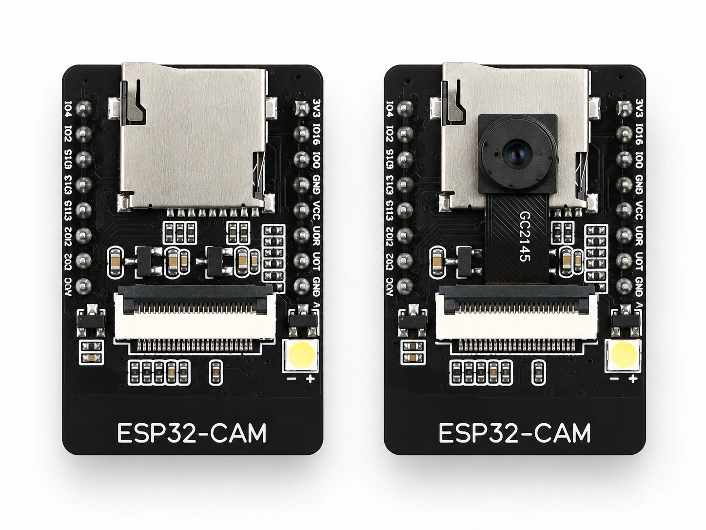
Figure: ESP32-CAM board showing OV2640 camera, microSD slot, flash LED, and headers.
What Is the ESP32-CAM?
The ESP32-CAM is a small camera development board made by AI-Thinker, not by Espressif. It combines AI-Thinker's ESP32-S module, built around an Espressif ESP32 chip, with an OV2640 camera, PSRAM, and a microSD card slot.
Three names are often mixed up in product listings:
- ESP32: Espressif's Wi-Fi and Bluetooth system-on-chip (SoC), the processor that runs your firmware.
- ESP32-S: AI-Thinker's module, which contains the ESP32 chip and its SPI (Serial Peripheral Interface) flash under a metal shield, plus a PCB antenna.
- ESP32-CAM: The complete development board, which integrates the camera connector, a separate PSRAM chip, a microSD slot, voltage regulators, an onboard flash LED, and dual 8-pin headers.
AI-Thinker designed the board to run on its own as a minimum system or to plug into a carrier board. Typical uses include Wi-Fi image streaming, still capture to a microSD card, remote monitoring, and QR code recognition.
ESP32-CAM Specifications
The ESP32-CAM pairs a dual-core ESP32 with 520 KB of on-chip SRAM (static RAM), external PSRAM, and a 2-megapixel OV2640 camera, and it runs from a 5 V supply. The values below come from AI-Thinker's specification and Espressif's ESP32 datasheet.
| Parameter | ESP32-CAM Value | Why It Matters |
|---|---|---|
| Module | AI-Thinker ESP32-S, with an Espressif ESP32 chip | Firmware targets the original ESP32 series |
| CPU | Dual-core 32-bit, up to 240 MHz | Handles capture, JPEG streaming, and Wi-Fi together |
| On-chip SRAM | 520 KB | Too small for most camera frame buffers |
| PSRAM | 4 MB in AI-Thinker's original specification; 8 MB on its current product page | Holds frame buffers; the ESP32 maps up to 4 MB at a time |
| SPI flash | 32 Mbit (4 MB) | Stores firmware |
| Camera | OV2640, 1600 × 1200 maximum; OV7670 also supported | Sets the resolution ceiling |
| Storage | microSD slot, up to 4 GB per AI-Thinker | Saves images without a network |
| Wireless | 2.4 GHz Wi-Fi 802.11 b/g/n; Bluetooth 4.2 BR/EDR (Classic) and Bluetooth LE | Wi-Fi carries the images |
| Antenna | Onboard PCB antenna, 2 dBi gain | Needs clearance from metal |
| Supply | 5 V | An onboard regulator produces 3.3 V |
| Supply current at 5 V | 180 mA with the flash LED off; 310 mA with the flash LED at maximum brightness | Typical figures: Wi-Fi transmit peaks run higher |
| Size | 27 × 40.5 × 4.5 mm | Fits small enclosures |
| Operating temperature | −20 to 85 °C | Sets the maximum ambient temperature around the board |
Clone boards sold under identical part numbers may use alternative components; always verify the vendor's schematic before relying on specific hardware tolerances.
What Can the ESP32-CAM Capture?
The OV2640 captures up to 1600 × 1200 pixels and compresses frames to JPEG directly on the sensor. This on-board compression maintains small file sizes necessary for reliable Wi-Fi streaming, making JPEG the standard format for this platform.
ESP32-CAM Frame Sizes and PSRAM
Espressif's esp32-camera driver requires external PSRAM for all capture modes except JPEG at CIF resolution or lower.
| Frame Size | Resolution | JPEG Without PSRAM? |
|---|---|---|
| QVGA | 320 × 240 | Yes |
| CIF | 400 × 296 | Yes |
| VGA | 640 × 480 | No, PSRAM required |
| SVGA | 800 × 600 | No, PSRAM required |
| HD | 1280 × 720 | No, PSRAM required |
| UXGA | 1600 × 1200 | No, PSRAM required |
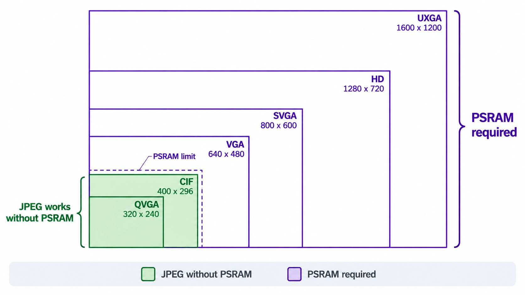
Figure: ESP32-CAM frame sizes from QVGA to UXGA drawn to scale
ESP32-CAM Image Formats, Frame Rates, and Video
Three limits shape what the camera delivers in practice:
- Uncompressed formats: The OV2640 also outputs YUV and RGB565 data. The driver documentation notes that writing these larger frames to PSRAM is slow, which can cause image data to be lost, especially with Wi-Fi active.
- Frame rate: The rate depends on frame size, JPEG quality, the camera clock, and Wi-Fi throughput. The OV2640 datasheet lists 15 frames per second at 1600 × 1200 as the sensor's maximum, not a figure for this board.
- Video: The ESP32 has no hardware video encoder. Firmware streams video as a sequence of JPEG frames, commonly as Motion JPEG (MJPEG) over HTTP.
Some boards ship with other sensors, such as the OV3660, which the driver also supports. Confirm that a replacement camera matches the board's connector pinout and supply rails before swapping it.
ESP32-CAM Pinout: Which GPIO Pins Are Free?
Most ESP32-CAM GPIOs are already dedicated to the camera, PSRAM, or microSD slot. The two 8-pin headers expose ten GPIO numbers, and how many are free depends mainly on whether your firmware uses the microSD card.
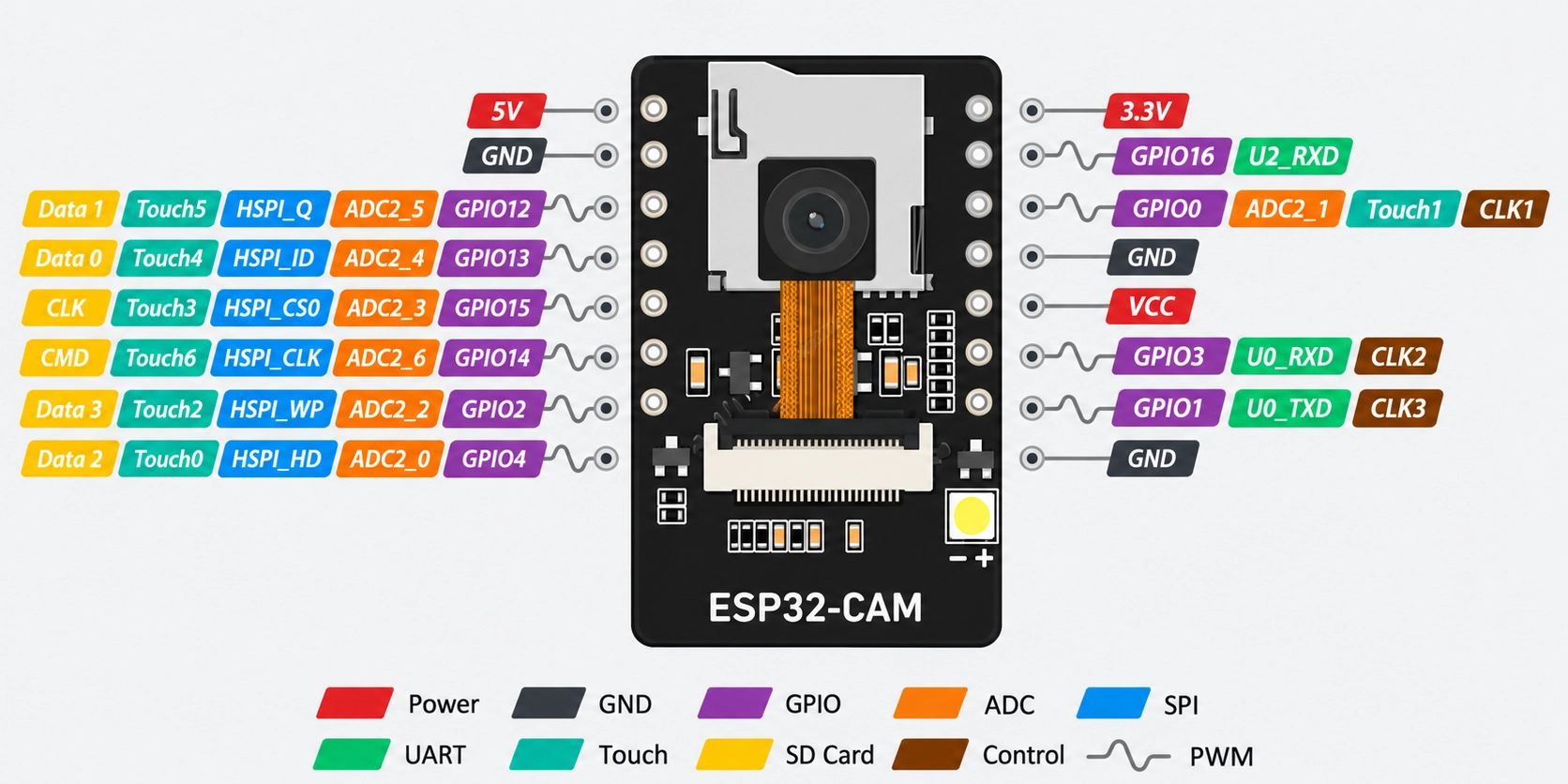
Figure: ESP32-CAM pinout showing both 8-pin headers color-coded by camera
ESP32-CAM Header Pins
The headers carry these pins:
- 5V-side header: 5V, GND, GPIO12, GPIO13, GPIO15, GPIO14, GPIO2, and GPIO4.
- 3V3-side header: 3V3, GPIO16, GPIO0, GND, VCC, U0R (GPIO3), U0T (GPIO1), and GND.
U0R and U0T are the receive and transmit pins of UART0, the first of the ESP32's UART (universal asynchronous receiver-transmitter) serial ports. The VCC pin connects to either the 3.3 V or 5 V rail, depending on which of the two 0 Ω resistors is fitted on the board.
GPIOs Used by the Camera, microSD Card, and PSRAM
| Function | GPIOs | On the Headers? |
|---|---|---|
| Camera data D0 to D7 | GPIO5, GPIO18, GPIO19, GPIO21, GPIO36, GPIO39, GPIO34, GPIO35 | No |
| Camera clock and sync (XCLK, PCLK, VSYNC, HREF) | GPIO0, GPIO22, GPIO25, GPIO23 | GPIO0 only |
| Camera control bus (SDA, SCL) | GPIO26, GPIO27 | No |
| Camera power switch | GPIO32 | No |
| microSD (CLK, CMD, DATA0 to DATA3) | GPIO14, GPIO15, GPIO2, GPIO4, GPIO12, GPIO13 | Yes |
| Flash LED | GPIO4, shared with microSD DATA1 | Yes |
| PSRAM chip select | GPIO16 | Yes |
| UART0 (TX, RX) | GPIO1, GPIO3 | Yes |
| Red status LED, active low | GPIO33 | No |
Once pin allocations are finalized, you can route the remaining GPIOs on a custom carrier board, source components directly from the JLCPCB Parts Library, and order turnkey PCB assembly.
How to Power the ESP32-CAM
Power the ESP32-CAM from a regulated 5 V supply via the 5 V pin. AI-Thinker recommends a 5 V supply rated for at least 2 A, warning that insufficient current capacity can introduce power-supply ripple and sensor noise that corrupt the video output.
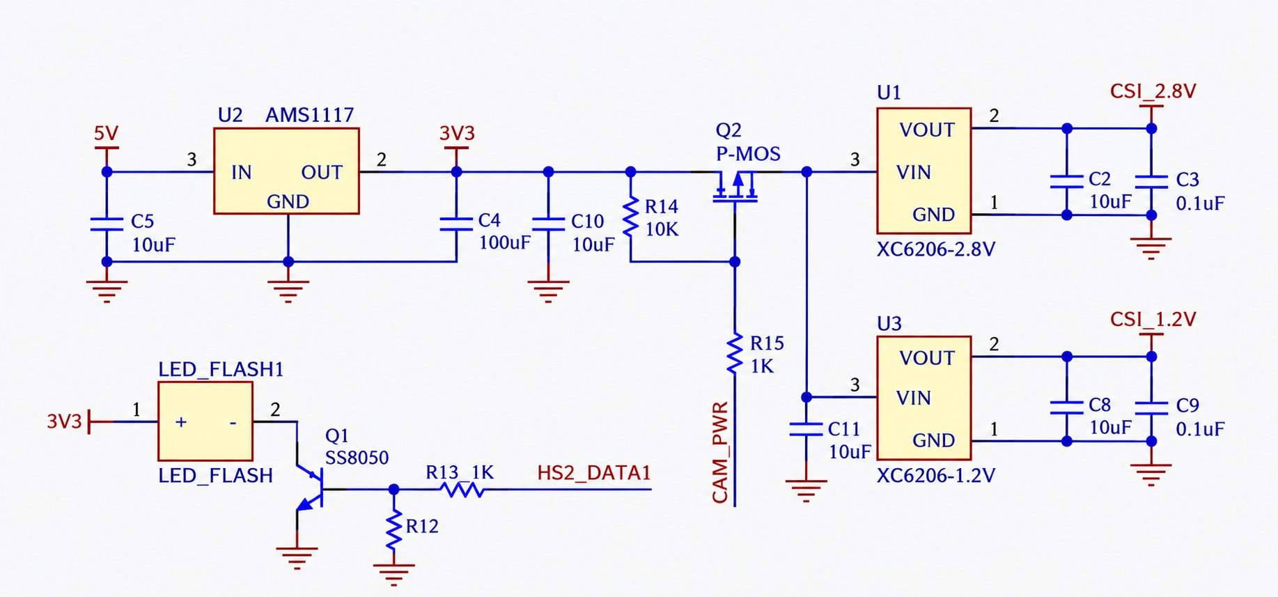
Figure: ESP32-CAM power path from the 5 V input through the AMS1117-3.3 regulator.
How the ESP32-CAM Regulates Its Supply
The board regulates its supply in two stages:
- 3.3 V rail: An AMS1117-3.3 low-dropout (LDO) regulator converts the 5 V input into the 3.3 V rail for the ESP32-S module, PSRAM, and microSD card.
- Camera rails: Two XC6206 regulators derive 2.8 V and 1.2 V for the camera. A P-channel MOSFET switches them, and AI-Thinker specifies driving GPIO32 low while the camera runs.
ESP32-CAM Current Consumption
AI-Thinker's current figures are measured at the 5 V input:
| Operating Condition | Current at 5 V |
|---|---|
| Flash LED off | 180 mA |
| Flash LED on, maximum brightness | 310 mA |
| Modem-sleep, minimum | 20 mA |
| Light-sleep, minimum | 6.7 mA |
| Deep-sleep, minimum | 6 mA |
These are board-level figures. The deep-sleep value includes the regulators and PSRAM, so it sits well above the ESP32 chip's own deep-sleep current.
Why Does the ESP32-CAM Reset During Wi-Fi Use?
Wi-Fi transmission draws short current peaks above AI-Thinker's 180 mA operating figure. Espressif's datasheet lists 240 mA typical for the ESP32 chip alone while transmitting 802.11b at +19.5 dBm, measured at 3.3 V with a 50% duty cycle.
The AMS1117 needs its input about 1.1 V above its output at 0.8 A (1.3 V maximum), and less at lower current. If high series resistance from inadequate wiring or an underpowered supply causes the 5 V input to dip during transient spikes, the 3.3 V rail will sag proportionally, triggering the ESP32's internal brownout detector (BOD) and causing a system reset.
To keep the rail stable:
- Use a supply rated for the peaks: Follow AI-Thinker's 5 V, 2 A recommendation rather than sizing for the 180 mA operating figure.
- Keep power leads short: Long jumper wires and thin USB cables add resistance that deepens each voltage dip.
- Add bulk capacitance at the 5V pin: The board carries only 10 µF at the regulator input, so a larger electrolytic capacitor across 5V and GND helps absorb current steps.
The 3V3 header pin connects directly to the board's 3.3 V rail. Feeding a regulated 3.3 V there bypasses the AMS1117, but it is outside AI-Thinker's 5 V specification, and the source must still handle the transmit peaks.
How to Program the ESP32-CAM
Because the board lacks an onboard USB interface, programming requires a 3.3 V USB-to-serial adapter connected to UART0. Holding GPIO0 low during a hardware reset forces the ESP32 into download mode.
Wiring the ESP32-CAM to a USB-to-Serial Adapter
Set the adapter's logic level to 3.3 V, because the ESP32's I/O pins are not rated for 5 V signals.
| USB-to-Serial Adapter | ESP32-CAM Pin |
|---|---|
| TX | U0R (GPIO3) |
| RX | U0T (GPIO1) |
| GND | GND |
| 5V | 5V, only if the adapter can supply the current peaks |
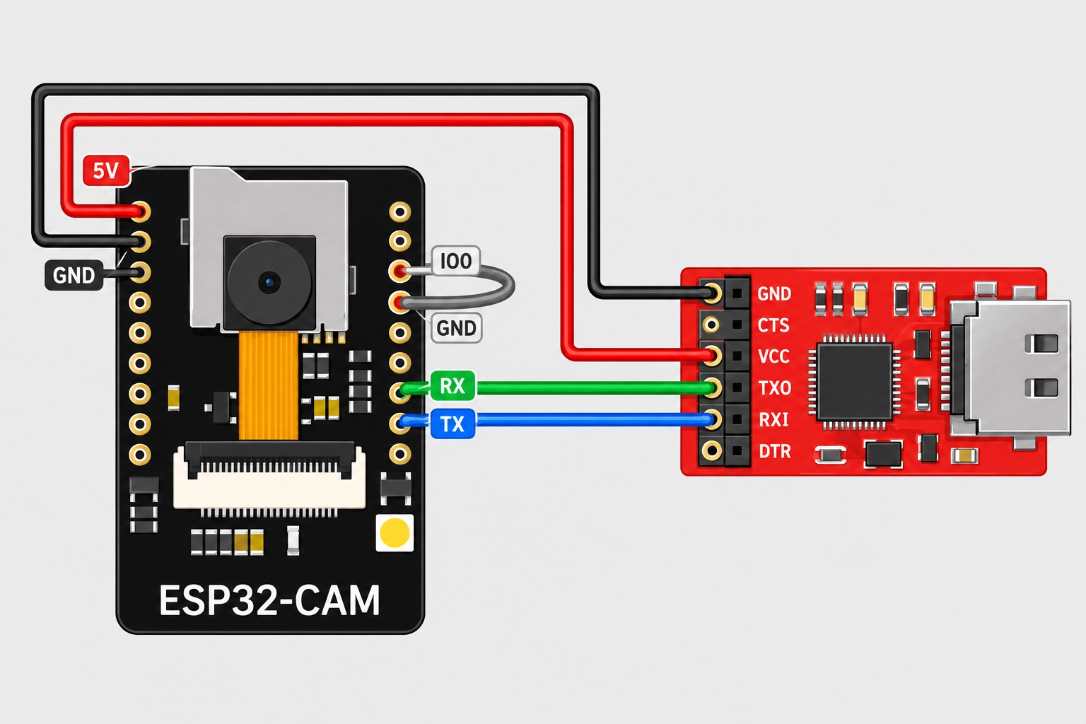
Figure: Wiring diagram of a USB-to-serial adapter connected to the ESP32-CAM.
Uploading Firmware to the ESP32-CAM
Follow this sequence for each upload:
- Connect GPIO0 to GND: Fit a jumper between GPIO0 and the GND pin next to it.
- Reset the board: Press the reset (RST) button or cycle the 5 V supply, so the ESP32 samples GPIO0 low and enters download mode.
- Upload the firmware: In the Arduino IDE, select the "AI Thinker ESP32-CAM" board. In the CameraWebServer example, enable the CAMERA_MODEL_AI_THINKER pin definition before uploading.
- Remove the jumper: Disconnect GPIO0 from GND.
- Reset again: Press RST so the board boots the new firmware from flash.
Note
Leave GPIO0 unconnected in normal operation. It carries the camera clock, and AI-Thinker advises against tying it high or low while the camera runs.
How to Use ESP32-CAM on a Custom PCB
Integrating the ESP32-CAM module into a custom hardware design is easiest when utilizing it as a daughter board on a carrier PCB. The carrier supplies a stable 5 V rail, programming access, and connections to the free GPIOs, while the ESP32-CAM keeps its camera and PSRAM.
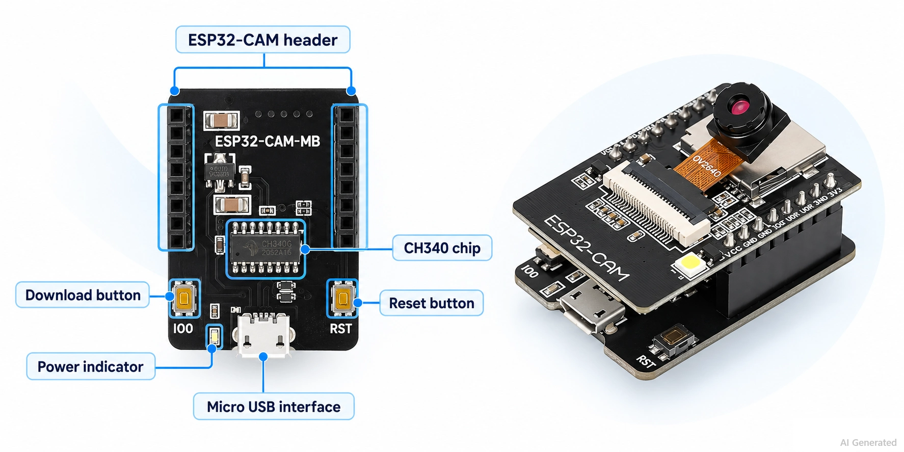
Figure: ESP32-CAM plugged into a custom carrier PCB
When to Design Your Own ESP32 Camera Board
If a product needs native USB, automatic reset, more free pins, or lower sleep current, design the camera board around a module instead. Espressif's camera driver supports the ESP32, ESP32-S2, and ESP32-S3.
The ESP32-S3 adds an 8- to 16-bit DVP (digital video port) camera interface and a USB Serial/JTAG controller, enabling firmware to be uploaded over USB without a bridge chip. The guide to designing an ESP32-S3 development board walks through such a layout.
Conclusion
The ESP32-CAM is AI-Thinker's ESP32 Wi-Fi camera board: an ESP32-S module, an OV2640 camera, PSRAM, and a microSD slot in a single board.
Program it via UART0, with GPIO0 held low at reset, power it from a 5 V supply that can handle current peaks, and plan around the few GPIOs the camera and microSD card leave free. Planning for these constraints early helps the board boot reliably, whether it sits on a breadboard or a custom carrier PCB.
FAQs About the ESP32-CAM
Q: Does Espressif make the ESP32-CAM?
No. AI-Thinker designs and sells the board. Espressif makes the ESP32 chip inside AI-Thinker's ESP32-S module and maintains the esp32-camera driver.
Q: Does the ESP32-CAM Have Bluetooth?
Yes. While the underlying ESP32 chip supports Bluetooth 4.2 BR/EDR and BLE, most camera applications utilize Wi-Fi to achieve the necessary throughput for streaming JPEG frames.
Q: Can the ESP32-CAM Work Without Wi-Fi?
Yes. Firmware can capture JPEG images and save them to the microSD card with Wi-Fi turned off, for example, in a time-lapse or motion-triggered logger.
Q: Can the ESP32-CAM Record Video?
Only as a sequence of JPEG frames. The ESP32 has no hardware video encoder, so firmware streams frames as MJPEG or writes them to the microSD card.
Q: What Resolution Can the ESP32-CAM Capture?
Up to 1600 × 1200 pixels with the OV2640 camera. JPEG frames larger than 400 × 296 require the board's PSRAM, and the frame rate depends on the resolution and JPEG quality.
Popular Articles
• SMD Resistor Package Sizes: Complete Size Chart, Footprints & How to Choose
• How to Solder SMD Components Like a Pro [2026 Updated]
• SMD Resistor Codes: How to Read 3-Digit, 4-Digit, and EIA-96 Markings
• SMD Capacitor Codes: Identification, Markings, and Polarity
• SMD Capacitor Sizes: Complete Size Chart and Selection Tips for PCB Design and Assembly
Keep Learning
What Is the ESP32-CAM, and How to Wire, Power, and Program It?
Key Takeaways Board, not chip: The ESP32-CAM is an AI-Thinker development board, not an Espressif product. It carries AI-Thinker's ESP32-S module, an OV2640 camera, PSRAM, a microSD slot, and a flash LED. No USB port: The board has no USB connector or USB-to-UART bridge, so you program it via its serial pins using a 3.3 V USB-to-serial adapter, with GPIO0 held low at reset. Few free pins: The camera, PSRAM, and microSD card occupy most GPIOs. With the microSD card unused, GPIO2, GPIO4, GPIO12, GPIO13,......
ESP32 Versions: Which One Should You Use for Your Project?
Key Takeaways Radios decide first: ESP32 versions differ mainly in their radios, CPU cores, and peripherals. Common defaults: The ESP32-C3 suits low-cost Wi-Fi and Bluetooth LE, the ESP32-S3 suits camera, display, voice, and on-device AI. Original ESP32: The chip is still in production and remains the choice for Bluetooth Classic. Versions without Wi-Fi: The ESP32-H2 targets battery-powered Thread and Zigbee devices. Chip, module, or board: Prototype on a development board, then design a module onto y......
SOIC Package: A Complete Guide to Specifications, Types, Uses, and SMT Assembly
As designs transition from legacy through-hole components to high-density Surface Mount Technology (SMT), the Small Outline Integrated Circuit (SOIC) remains the industry standard for operational amplifiers, flash memory, sensors, and microcontrollers. It reflects a well-balanced engineering design, offering a practical compromise between the miniaturisation demanded by modern consumer electronics and the ruggedness required for industrial applications. In this guide, you will learn: SOIC package dime......
What Is a 100nF Capacitor and How Do You Choose the Right One
Key Takeaways Value: A 100nF capacitor has a nominal capacitance of 0.1 µF, or 100,000 pF, and all three names describe the same part value. Marking: Many through-hole ceramic and film capacitors use the three-digit code 104, while most SMD MLCCs are unmarked. Main use: Its most common function is local decoupling at an IC power pin, where it supplies fast transient current and shunts high-frequency noise to ground. Default choice: For general decoupling, an X7R or X5R MLCC is a common starting point;......
SMD Resistor Package Sizes: Complete Size Chart, Footprints & How to Choose
Surface Mount Device (SMD) resistors are fundamental to modern electronics, and selecting the correct package size is a crucial engineering decision that impacts a PCB’s electrical performance, thermal reliability, and manufacturing cost. In this article, you will find practical, authoritative guidance on: The complete SMD resistor size chart (01005 to 2512) with exact dimensions and power ratings. Recommended PCB footprints and guidelines for reflow reliability. Critical trade-offs concerning power d......
PCB Connector Types Explained: Categories, Comparison, Applications and How to Choose the Right One
PCB connectors are essential components for connecting circuit boards with external devices, cables, or other PCBs. Choosing the right connector type affects signal reliability, mechanical stability, and overall product performance. Factors such as current rating, frequency requirements, pitch size, and mounting method should be considered during selection. In this guide, you will learn: The major types of PCB connectors and their applications. How different connector types compare. How to select the ......