A Deep Dive into Polyimide PCB Materials for High-Thermal Stability
18 min
- Understanding Polyimide as an Advanced PCB Material
- Polyimide Key Properties vs Traditional FR-4 Substrates
- Critical Engineering Advantages of Polyimide PCBs
- Mission-Critical Applications of Polyimide PCBs Across Industries
- Advanced Substrate Processing and Fabrication at JLCPCB
- FAQ about Polyimide PCB
- Conclusion
Key Takeaways
- Two Form Factors: Available as flexible film (bends without cracking) or rigid glass laminate (structural stability).
- Extreme Heat Resistance: Handles operating temperatures over 200°C with a Tg up to 250°C-410°C.
- High Via Reliability: Expands only 1.2% in the z-axis (50°C to 260°C), preventing plated hole cracks.
- Mandatory Baking: Absorbs up to 2.8% water weight, requiring a pre-reflow bake to avoid delamination.
- JLCPCB Flex Support: Best for high-reliability uses; JLCPCB supports 1 to 4-layer flexible polyimide FPCs.
A polyimide PCB can continue to function at temperatures at which FR-4 has already softened. That's why it ends up in engine bays, satellites, and downhole drilling tools. The trade-off is cost: polyimide laminates can be several times more expensive than conventional FR-4, so using them only makes sense when the application genuinely needs their thermal and mechanical advantages.
In this guide, you will learn:
- What polyimide is and why it exists in two different forms
- How do Tg, CTE, and decomposition temperature compare with FR-4
- Where its moisture behavior helps and where it hurts
- Which industries pay for it, and what they get back
- What JLCPCB can actually build in polyimide today
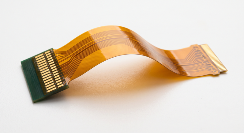
Figure 1: A polyimide flexible circuit
Understanding Polyimide as an Advanced PCB Material
There is one reason why polyimide is included in a bill of materials. It maintains its dimensional and chemical stability at temperatures that would destroy ordinary laminate. Standard FR-4 is rubbery at 140 °C; anything hotter requires a different resin backbone. That backbone is polyimide, and it comes as two very different products, both by the same name.
What is Polyimide and Its Chemical Composition in Electronics
Polyimide is a polymer that is constructed from the imide ring, which is a loop of nitrogen locked into an aromatic chain. A dianhydride is reacted with a diamine to make a soluble intermediate known as a polyamic acid, which is then reacted by the manufacturer. Imidization is the process of closing the ring and releasing water at a high temperature. As soon as the ring is closed, there is no weak link in the chain. Therefore, the material cannot be melted like a thermoplastic.
The reason for most of the following is that cured polyimide does not soften, but decomposes. No design around a sharp melting point. Ordinary epoxy has aliphatic segments that expose an easy target for heat to chemically break the chain, starting at about 400 C. The chemistry costs a lot more than FR-4, and that is why polyimide is sold for several times the price of FR-4.
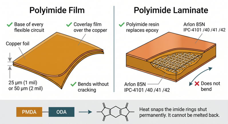
Figure 2: The two forms of polyimide used in PCB manufacturing
There are two different polyimides, and the most frequent material selection error is to mix them up. DuPont Kapton HN is an unreinforced polyimide film that has no glass. It comes in sheets from 12.5 to 125 µm (0.5 to 5 mil) thick. Glass-reinforced polyimide laminate is E-glass woven and impregnated with polyimide resin, such as Arlon 85N. They are both referred to as polyimide PCB material, but only the film can be bent.
Key Physical and Thermal Properties of Polyimide Substrates
The second-order transition of Kapton HN lies between 360 and 410 C, which DuPont considers to be the glass transition temperature of Kapton HN. This is continuous service to 260 C, and occasional service to 400 C is OK. The film is usable at the cold end down to -269 C. Thus, a cryogenic instrument and a furnace controller can be made of the same base material. It fractures at 221 MPa and 75% elongation, thus allowing the sheet to bend rather than crack when folded in a 25 µm (1 mil) sheet.
The heat resistance is not equal to the heat conduction. Polyimide is only proficient at the first of those. Kapton HN moves heat at 0.12 W/mK and Arlon 85N at 0.20 W/mK. Both are lower than the 0.3 W/mK of common FR-4. A hot component is placed on a polyimide board, which, in turn, does nothing to cool the component. Even if you need to move that heat, you still need a copper area, thermal vias, or a metal core.
| Property | Polyimide Film (Kapton HN) | Rigid Polyimide Laminate (Arlon 85N) | What It Means for Your Board |
|---|---|---|---|
| Glass transition (Tg) | 360 to 410 C | 250 C | Neither softens at lead-free reflow peaks near 260 C |
| Decomposition | No melting point, decomposes above 500 C | 387 C onset, 407 C at 5% mass loss | This, not Tg, is the true ceiling |
| Thermal conductivity | 0.12 W/mK | 0.20 W/mK | Survives heat but does not spread it |
| Dielectric constant | 3.4 to 3.6 at 1 kHz | 4.2 at 1 MHz | The unreinforced film is the better impedance substrate |
| Dissipation factor | 0.002 at 1 kHz | 0.010 at 1 MHz | Lower loss than FR-4, still not an RF laminate |
| Water absorption | 2.8% in 24 h at 23 C | 0.27% | The film must be baked before it sees reflow. |
The film wins on every electrical property because it carries no glass weave. It loses badly on moisture for exactly the same reason. Those last two rows are the whole trade-off in one place.
Polyimide Key Properties vs Traditional FR-4 Substrates
FR-4 is the default for good reasons, and it handles most of what gets built. The comparison below only matters in three situations. A board has to live somewhere hot, cycle hard, or bend. Those are the conditions where FR-4 finally runs out of margin.
Glass Transition Temperature (Tg) and Thermal Expansion Profile
Tg is the temperature at which the resin changes from a glassy state to a rubbery state. The resin underneath it keeps the glass weave and the copper in place. The resin above it becomes soft, and the board swells three to five times as much across the thickness. Standard FR-4 crosses that line at 130-140 C, while polyimide laminate does not even cross until 250 C.
A plated through-hole is like a copper rivet going through a series of washers. Washers = laminate layers. When heated, they will swell (along the rivet's axis) on the board. Copper expands 17 ppm/C, and FR-4 above its Tg expands 250 to 300 ppm/C. Thus, the washers exert a great deal more force than the rivet is able to stretch. The barrel wall becomes thin, and a crack develops and appears as an intermittent opening.
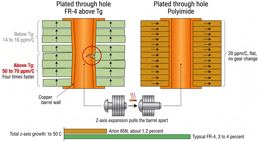
Figure 3: The rivet and the washer stack
Measured across the full assembly range of 50 to 260 C, Arlon 85N grows 1.2% in the z-axis. Typical FR-4 grows roughly 3 to 4% over the same span. That gap is the entire argument for polyimide in multilayer work. Every reflow pass, every rework cycle, and every field thermal shock spends the difference. A board with two reflow passes plus two rework events has already crossed 260 C four times. If temperature is your only concern, how to select the Tg of a PCB shows that high-Tg FR-4 still wins.
| Parameter | Standard FR-4 | High-Tg FR-4 | Polyimide Laminate | Practical Consequence |
|---|---|---|---|---|
| Tg | 130 to 140 C | 170 to 180 C | 250 C | Sets when the resin goes rubbery |
| Decomposition (5% loss) | Around 310 C | Around 340 C | 407 C | Sets the real destruction point |
| Z-axis expansion, 50 to 260 C | 3 to 4% | 2.8 to 3.5% | 1.2% | Drives barrel cracking in plated holes |
| Continuous operating limit | Around 105 C | Around 130 C | 200 C and above | Decides whether the board survives its environment |
| Relative material cost | Baseline | Modestly above baseline | Several times baseline | Decides whether the project can afford it |
Dielectric Constant, Loss Tangent, and Moisture Absorption Rates
Rigid polyimide laminate measures Dk 4.2 and Df 0.010 at 1 MHz. That puts it level with FR-4 on permittivity but clearly ahead on loss. FR-4 typically runs Df 0.017 to 0.025 over the same range, so polyimide roughly halves the dielectric loss. That helps a digital board with fast edges. But it is nowhere near a purpose-built RF laminate such as RO4003C at Df 0.0027.
Unreinforced film does better on both counts because it contains no glass weave. Kapton HN sits at Dk 3.4 to 3.6 with Df 0.002 at 1 kHz. JLCPCB's flex impedance calculator uses a dielectric constant of 3.3 for its polyimide stack. Removing the weave also removes the fiber weave skew. That skew becomes a real problem on FR-4 differential pairs above roughly 5 Gbps. So an LVDS or MIPI pair on a flex tail is easier to control than the same pair on woven laminate.
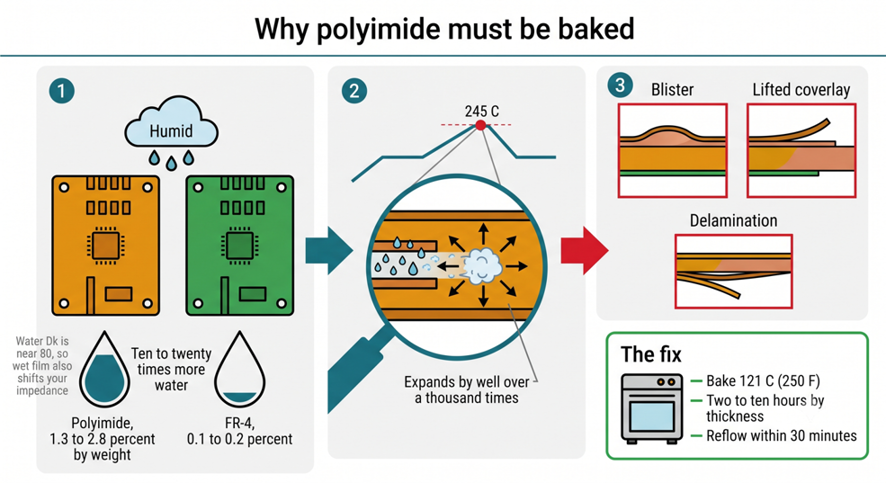
Figure 4: Moisture is the real weakness
Moisture is where polyimide hands the advantage back. Kapton HN takes up 2.8% of its own weight in water after 24 hours at 23 C. At equilibrium in 50% relative humidity, it still holds about 1.8%. FR-4 absorbs 0.1 to 0.2% and Arlon 85N laminate 0.27%, so the bare film is roughly ten times thirstier. Water has a dielectric constant of 78. That means absorbed moisture lifts both Dk and Df and quietly shifts a controlled impedance line off target.
Critical Engineering Advantages of Polyimide PCBs
Superior Resistance to Extreme Operating Temperatures and Thermal Shock
After a board is operated continuously at a high temperature, the decomposition temperature becomes more important than the Tg. Arlon 85N starts losing weight at 387 C and reaches 5% weight loss at 407 C, whereas typical FR-4 reaches the same point between 310 C and 350 C. Polyimide can be maintained at 200 C for an infinite period of time with those 60 to 90 degrees of headroom, rather than aging out. Resin aging is cumulative; a board that has been exposed to 150 C for years is slowly cooked.
Thermal shock is a separate test from steady heat, and it is the one that breaks joints. IPC-TM-650 method 2.6.7 cycles boards between temperature extremes. The mismatch between copper and resin then has to do its damage quickly. Polyimide's low z-axis expansion means each cycle stores less strain in the barrel wall. That is why it dominates in equipment that nobody can service afterward. A down-hole logging tool runs at 175 to 200 C, and an engine control unit at 150 C. Both sit well outside what FR-4 tolerates for long.
Outstanding Mechanical Durability and Chemical Resistance
Polyimide film is genuinely tough rather than merely heat-resistant. Kapton HN breaks at 221 MPa with 75% elongation, so a thin sheet stretches noticeably before it tears. Coverlay-protected flex circuits are rated past 200,000 dynamic bend cycles. That figure only holds when the copper is rolled annealed rather than electrodeposited. So a flex tail survives a laptop lid hinge or a folding phone, where a rigid board would crack in weeks.
Chemical resistance comes from the same aromatic backbone that supplies the heat performance. Fuels, hydraulic fluids, greases, and most organic solvents leave cured polyimide alone. That is why it survives an engine bay and a machine tool enclosure. The exception is strong alkali, because concentrated bases hydrolyze the imide ring and open the chain. Repeated steam autoclaving at 121 to 134 C attacks it in the same manner. So medical assemblies that are sterilized hundreds of times need a conformal coat over the polyimide.
Mission-Critical Applications of Polyimide PCBs Across Industries
Polyimide shows up wherever replacing a failed board is impossible, expensive, or dangerous. The industries below share that one constraint. They have almost nothing else in common.
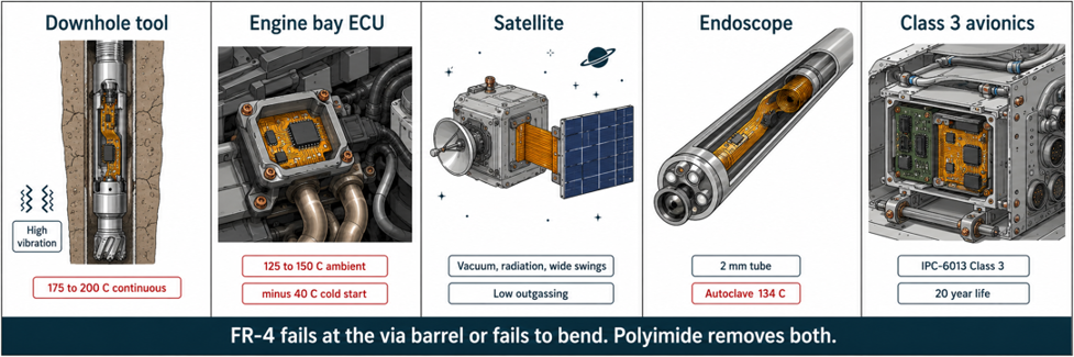
Figure 5: Where polyimide earns its cost
Aerospace, Automotive, and Industrial Control High-Heat Environments
Satellites have two punishments, and polyimide serves two purposes. An LEO spacecraft orbits the Earth about every 90 minutes. Thus, a 15-year mission results in approximately 87,000 thermal cycles on the harness. The vacuum outgassing limit is added on top of that, and very little else passes muster.
As engine bays became more compact, automotive electronics occupied the same space. The toughest ambient class is AEC-Q100 Grade 0, which is -40 to +150 C. That includes transmission-mounted controllers and anything that is bolted near an exhaust. The resin ages, but FR-4 will last through it, and the Tg will shift down. Until one of the barrels opens, plated barrels then accumulate cycle damage. That's not the case with polyimide, and it has now become the norm for on-engine sensing.
Industrial control puts the same demand on boards for far less glamorous reasons. The temperatures are just as high, but the budgets rarely are:
- Down-hole drilling and logging tools run at 175 to 200 C for days, with heavy vibration on top of the heat.
- Furnace and kiln controllers sit close enough to the process that the board itself holds 200 C.
- Welding and induction heating equipment combine high ambient temperature with strong electromagnetic fields.
- Aircraft engine sensing faces heat and vibration together, with no service access in flight.
High-Reliability Defense and Medical Sensing Electronics
Defense hardware buys polyimide for qualification reasons as much as thermal ones. Flexible printed wiring for military use was long built to MIL-P-50884. Current work is qualified to IPC-6013 Class 3, the tier for equipment where downtime is unacceptable. Class 3 tightens annular ring, plating thickness, and thermal stress requirements. So a substrate that shifts less during testing makes those limits much easier to hold. Radar arrays, avionics backplanes, and seeker heads all end up on polyimide.
Medical electronics make the leap to polyimide film due to its close bending radius. The 25 µm (1 mil) substrate can also be folded almost to a 1 mm (40 mil) bend radius without cracking the copper, so that a sensor array can be inserted down a catheter. This film is non-dimensionally changing in ethylene oxide and gamma sterilization. It is the basis of hearing aids and ultrasound probes, endoscope camera assemblies, and implantable leads.
| Environment | Peak Board Temperature | Recommended Substrate | Why This Choice |
|---|---|---|---|
| Consumer, office, indoor equipment | Below 105 C | Standard FR-4 | Cheapest option that never approaches its Tg |
| Dense multilayer, power supplies, and LED drivers | 105 to 130 C | High-Tg FR-4 | Extra Tg margin protects barrels through rework |
| Under-hood automotive, industrial control | 130 to 175 C | Polyimide laminate or polyimide flex | FR-4 resin ages measurably at this temperature |
| Down-hole, aerospace, furnace control | 175 to 250 C | Polyimide | Only substrate with decomposition headroom left |
| Anything that bends in service | Any of the above | Polyimide film flex | Glass-reinforced laminate cracks when flexed |
Advanced Substrate Processing and Fabrication at JLCPCB
Polyimide at JLCPCB means flexible circuits, not rigid boards. The service is built around polyimide film as the base dielectric for FPCs. Rigid polyimide laminate is not in the catalog, and rigid-flex is not offered either at the time of writing. So a design that genuinely needs rigid polyimide has to go to a specialist fabricator. Everything below describes the flexible polyimide process as it actually runs.
Precision Lamination and High-Temperature Material Handling Capabilities
The base film comes in 25 µm (1 mil) and 50 µm (2 mil) thicknesses. Both adhesive and adhesiveless construction are available. Adhesiveless bonds the copper straight onto the polyimide, which removes the acrylic layer in between. That acrylic tops out near 105 C and epoxy adhesive near 155 C. An adhesiveless stack holds past 300 C, so choose it whenever the part flexes repeatedly or sees reflow twice.
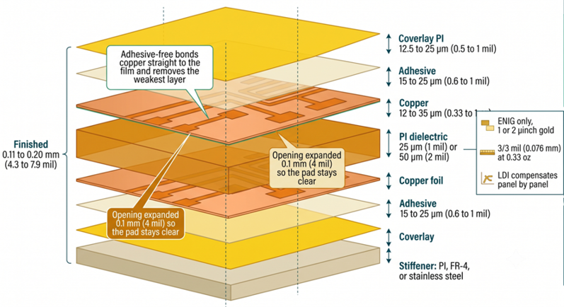
Figure 6: Anatomy of a JLCPCB polyimide flex
A polyimide flex build stacks up in a fixed order. Knowing that order makes the DFM feedback much easier to read:
- Base polyimide film, 25 µm (1 mil) or 50 µm (2 mil), carrying the copper foil.
- Copper foil, 12 µm (0.33 oz), 18 µm (0.5 oz), or 35 µm (1 oz), rolled annealed where the board bends.
- Coverlay, a second polyimide film laminated under vacuum, in yellow, black, white, or transparent.
- Stiffener, polyimide at 0.1 to 0.25 mm (4 to 10 mil), FR-4 at 0.1 to 1.6 mm (4 to 63 mil), or stainless steel at 0.1 to 0.3 mm (4 to 12 mil).
- Surface finish, ENIG at 1 or 2 microinches of gold over nickel, since HASL would deform the film.
- Optional EMI shielding film at 18 µm (0.7 mil) laid over the coverlay.
Layer count runs from one to four, and every added layer costs flexibility. Four-layer flex ends up stiff enough for static installations rather than a moving hinge. Minimum trace and space is 0.1 mm (4 mil) on 1 oz copper. Holes run from 0.1 to 6.5 mm (4 to 256 mil), and the largest regular panel is 234 by 490 mm (9.2 by 19.3 in).
Strict Material Quality Verification and Reliable Manufacturing Standards
Flex fabrication is governed by a different set of IPC documents than rigid work. IPC-4204 specifies the flexible copper-clad dielectric itself. IPC-4203 covers the coverlay and bonding films, and IPC-2223 is the sectional design standard. Finished panels are then qualified against IPC-6013, which is the flex counterpart to IPC-6012. Reading those four instead of the rigid set will save you a round of DFM questions.
- Matching coverlay openings exactly to the pad is the most frequent error. Vacuum lamination registers the coverlay only to about ±0.1 to ±0.15 mm (4 to 6 mil). So a fraction of your pads end up partly covered and unsolderable. Expand every opening by at least 0.1 mm (4 mil) per side.
- Specifying electrodeposited copper in a bending zone looks harmless on a stackup drawing. ED copper has a columnar grain structure that fractures under repeated flexure. So call out rolled annealed copper anywhere the part actually moves.
- Skipping the pre-reflow bake costs whole panels rather than single joints. Polyimide holds enough absorbed water to blister the laminate once it turns to steam. Bake for 2 to 4 hours at 120 C if the vacuum bag has been open.
Incoming film is verified for thickness and lamination integrity. Finished boards go through an electrical test before they ship. Moisture control matters far more here than on FR-4, so panels are baked and vacuum-sealed. Ordering works like any other board. Upload your Gerbers to the JLCPCB quote page, pick flexible as the board type, and the price updates live.
FAQ about Polyimide PCB
Q: Is a polyimide PCB the same as a flexible PCB?
Not quite, though the two overlap heavily. Almost every flexible PCB uses polyimide film as its base. Polyimide also exists as a rigid glass-reinforced laminate that does not bend at all.
Q: What temperature can a polyimide PCB handle continuously?
Rigid polyimide laminate is good for 200 C and above. Polyimide film is rated to 260 C. Both figures assume that the components and the solder alloy can also survive that temperature.
Q: Should I just use polyimide to be safe?
No, because you would pay several times more for headroom you never use. Standard FR-4 is fine below about 105 C. High-Tg FR-4 covers most designs up to 130 C.
Q:Does JLCPCB manufacture rigid polyimide PCBs?
No. Polyimide at JLCPCB is available only as a flexible circuit material, in 25 µm and 50 µm base film. Rigid-flex is not currently offered either.
Q: Why does a polyimide board need baking before soldering?
Polyimide absorbs far more water than FR-4, up to 2.8% of its own weight. That water turns to steam in the reflow oven and blisters the board. A bake of 2 to 4 hours at 120 C drives it out first.
Conclusion
Polyimide is not an upgrade to FR-4 so much as a different answer to a different question. FR-4 is asked to be cheap, stiff, and adequate. Polyimide is asked to hold its dimensions when everything around it is hot, moving, or unreachable. Frame the choice that way, and it gets simple, because you only pay for the 250 C Tg when something demands it. The property that catches people out is moisture, so treat a polyimide board as one that needs baking.
Flexible polyimide is spreading faster than the rigid version. Folding displays, wearable sensing, and shrinking automotive modules all pull in the same direction. That trend is worth watching because a flex tail often removes a connector, a harness, and two failure points at once. If your next design has a hinge or an ambient temperature that FR-4 cannot handle, a polyimide flex from JLCPCB is a practical way to prototype it.

Popular Articles
• Understanding the Basics of Electronic Devices and Circuits
• Understanding Digital Circuit Timing: Setup Time, Hold Time, Contamination Delay & Clock Skew
• PCBs Explained: A Simple Guide to Printed Circuit Boards
• Guide to the Top 10 Commonly Used Electronic Components
• Digital 101: Fundamental Building Blocks of Digital Logic Design
Keep Learning
Polyimide Flex PCB: A Complete Guide for Engineers
A polyimide flex PCB can be folded about 285,000 times when the base film is 25 µm (1 mil) thick. Make that film 75 µm (3 mil), and the same MIT fold test gives up near 6,000 cycles. Bending is a strain problem, not a material problem. Copper sits above the center of the stack, so a bend forces it to stretch around the longer outer path. Figure 1: A polyimide flex circuit folded tight, with a stiffener holding the connector A thicker stack places the copper farther out, resulting in more stretch at th......
Flex PCB Bend Radius: Calculation, Minimum Radius & Design Guidelines
Flex PCB bend radius is the one dimension on an FPC that no design rule check will catch. Bend the circuit tighter than its material allows; the outer copper stretches from its elongation limit, and then it cracks. Figure 1: A flex circuit formed around a mandrel, with bend radius and stack thickness A flex circuit bends around a neutral axis near the middle of its stack. Copper below that line is squeezed, and copper above it is pulled. So the further a layer sits from the line, the harder it is to w......
Flexible Circuit Connector: Types, Features & Selection Guide
A flexible circuit connector clamps onto the bare copper at the end of a flex circuit, so nothing is soldered at that joint. The tail slides into the housing, and an actuator presses a row of spring contacts onto the pads. Every connector is built around one tail thickness. TE's 0.5 mm pitch 2328702 family expects 0.30 mm (12 mil) of flex, because the contact beams are deflected by exactly that dimension. Figure 1: Cross-section of a 0.5 mm pitch FPC connector with the tail inserted Feed it a bare sin......
FPC vs FFC: Understanding the Key Differences Between Flexible Circuit Technologies
The FPC vs FFC decision is really a question about how the copper was made. An FFC consists of flat copper strips laminated between two PET films. Every conductor runs straight from end to end at one fixed pitch, because nothing in that process can make a trace turn or branch. An FPC starts as copper-clad polyimide and is etched exactly like a rigid board. Traces can turn, taper, split onto a second layer, and land under a soldered component. The finished circuit can be as thin as 0.1 mm (4 mil). Figu......
A Comprehensive Guide to Capacitor ESR: What It Is, Good Values, and How to Measure It
Key Takeaways Definition: Capacitor ESR (equivalent series resistance) is the single resistance that represents the losses inside a real capacitor, from its electrodes, terminations, electrolyte, and dielectric. Why It Matters: Ripple current flowing through the ESR produces a ripple-voltage step on the supply rail and I²R heating in the capacitor, which limits the capacitor's ripple-current rating and service life. Conditions Matter: ESR varies with frequency, temperature, capacitance, case size, and......
Understanding IPC-6012 Standards for High-Reliability Rigid PCB Fabrication
Key Takeaways IPC-6012 vs. IPC-A-600: IPC-6012 is the binding specification, while IPC-A-600 is only for visual reference. Class 2 vs. Class 3: Class 3 requires thicker copper (25μm vs. 20μm) and zero plating voids. Coupon Verification: Quality is tested by microsectioning panel coupons after thermal stress. Upfront Callout: Specify the class on drawings upfront; boards cannot be upgraded later. IPC-6012 is the line on your fabrication drawing that decides what your supplier is allowed to ship. Most d......