
Selecting the Ideal Substrate Material for High-Performance PCBs
10 min
- Understanding Substrate Material in PCB Construction
- Key Properties That Define Substrate Performance
- How to Select the Best Substrate Material
- Manufacturing Considerations for Different Substrate Materials
- JLCPCB's Expertise in Substrate Material Selection and Fabrication
- FAQ about PCB Substrate Material
- Conclusion
Key Takeaways
Selecting the ideal PCB substrate material—balancing standard FR4 for general use with advanced Rogers or PTFE for high frequencies—is vital to prevent signal loss and thermal failure. Hybrid stackups perfectly optimize performance and cost , while JLCPCB guarantees a reliable, high-quality transition from rapid prototyping to volume production.
Ever wonder what's under all those shiny copper traces on a printed circuit board? That layer is the substrate material, and it is probably the most important consideration you need to take into account before you route any one of your traces. It will affect the way your signals spread, how your heat is kept under control, and ultimately, if your final product is reaching the standards you established for it.
If the wrong type of PCB substrate material is used, a large amount of signal may be lost at high frequencies, or the PCB may even experience thermal runaway in a power-dense design or mechanical failure in a harsh environment. If you get it right from the get-go, you save the expense of respins later. This guide will discuss what this material is, why it's important, compare the most popular substrate materials and their primary characteristics, and present a step-by-step approach to choosing the right material for your next project. Let's dive in.
Understanding Substrate Material in PCB Construction
What Substrate Material Is and Its Fundamental Role
Simply put, the insulating base material that is used to construct a PCB is called the Substrate. The non-conductive core sustains the copper foil, imparts mechanical stiffness, and electrically separates one conductor layer from the other. Imagine, in a substrate construction definition context, that it is the skeletal structure and insulation of your circuit board, all in one laminated piece.
The substrate has three vital functions at once. First, it serves as a dielectric, the insulating material between copper layers that has a direct impact on the speed of the signal and its impedance. Second, it is a mechanical platform that carries components and can endure soldering temperatures. Third, it is used as a thermal path, which removes heat from power components to the external environment.
Common Types of PCB Substrate Materials
The workhorse in the industry is FR4 (Flame Retardant 4). It is a Dk glass reinforced epoxy laminate which can be around 4.2 to 4.7 and a Tg of 130 to 180 degrees Celsius, depending on grade. It is suitable for most digital, power, and general-purpose designs. High-Tg FR4 is an improved version with a Tg higher than 170ºC and used for lead-free assembly processes.
- High-frequency materials for RF and millimeter wave applications are offered as Rogers Laminates. Popular variants include RO4003C (Dk 3.38, Df 0.0027) and RO4350B (Dk 3.48, Df 0.0037). They are vital components for antenna feeds, radar systems, and 5G infrastructure.
- For flexible and rigid-flex PCBs, the material of choice is polyimide. They are thermally stable to over 300ºC, and mechanically flexible for use in wearable electronics, medical devices, and aerospace cabling.
- The lowest dielectric losses of any substrate are available from PTFE (Teflon) substrates, which are good for satellite communications and mmWave radar (above 30 GHz).
Key Properties That Define Substrate Performance
Dielectric Constant, Loss Factor, and Thermal Characteristics
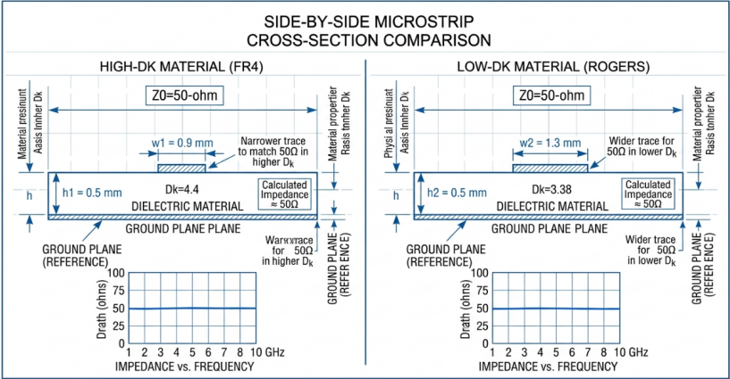
Dielectric constant (Dk): A measure of the effect of the substrate on the slowing of an electromagnetic wave as it passes through it compared with free space. The lower the Dk, the faster the signals will propagate and the easier it is to control impedance. A lower and more stable Dk also leads to lower timing skew and easier length matching for high-speed digital buses (such as PCIe Gen5, or DDR5).
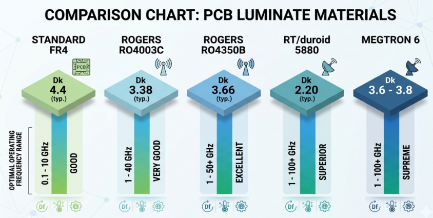
Also known as loss tangent, dissipation factor (Df) is a measure of the amount of signal energy absorbed by the substrate and turned into heat. The Df of standard FR4 is around 0.017 to 0.025, which is good for up to ~3 GHz. In addition, materials such as Rogers (Df 0.0027) or PTFE (Df below 0.001) are required. Thermal conductivity is the ability of the board to transfer heat from the hot spots to the cooler regions. Standard FR4 can only handle ~0.3W/mK; Aluminum MCPCBs can handle 1-4W/mK; Ceramic substrates can handle > 20W/mK.
How to Select the Best Substrate Material
Matching Material to Frequency, Power, and Application Needs
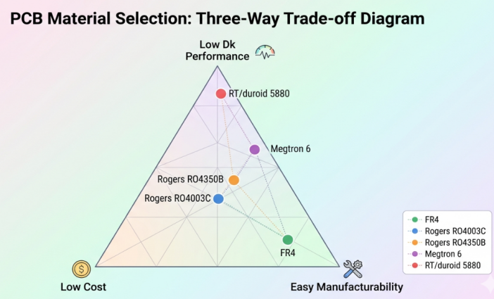
Choosing the right substrate is not a question of which is the best substrate - it is which is the best substrate in your particular application. A practical decision framework.
Determine the maximum frequency of your signal to be transmitted: If your highest frequency content is less than 1 GHz, then your standard FR4 should be fine. Consider high-performance FR4 options or hybrid stack-ups for frequencies greater than 1 GHz and up to 10 GHz. At frequencies around 10 GHz, substrates like Rogers, PTFE, or ceramic should be used to control insertion loss.
Calculate the board's total dissipated power, hot spot,s and what type of thermal dissipation is required. For higher power densities ( > 1-2W/cm2), standard FR4 may not suffice. Look for metal-core substrates, heavy copper builds, or ceramic solutions.
Balancing Cost, Performance, and Manufacturability
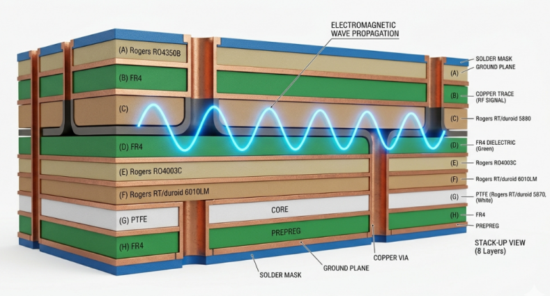
The Hybrid Stackup has been proven. In this approach, the RF signal layers, which require low loss, are fabricated from Rogers or PTFE material, and then laminated onto the power and low-speed digital routing of the FR4 core material. This gives you the best of both worlds - high frequency performance when you need it, and cost savings when you don't.
When it comes to cost vs. performance, keep the following in mind:
Volume: Cost-effectiveness of high-performance materials is optimized through panel utilization, as only a higher production volume makes this possible.
Fast lead time: Standard FR4 is available in all locations. Additional lead time may be necessary for specialty materials such as Rogers or Isola laminate, 1-3 weeks.
Yield impact: Certain materials are more difficult to work with, resulting in less manufacturing yield and increasing the effective cost.
Manufacturing Considerations for Different Substrate Materials
Process Adjustments and Quality Control
Not all substrate materials perform the same on the production floor. Adjustments are required for each material along the fabrication process. The differences in material properties first occur in the drilling process. FR4 can be drilled cleanly with standard tungsten carbide drills; Rogers material will need to be adjusted for feed rates. As PTFE tends to deform and not cut cleanly, special drill geometries are required. It should be noted that Ceramic Substrates are not at all suitable for mechanical drilling and must be laser-processed.
There are many different lamination parameters. Standard FR4 laminates at about 175 - 185°C and 200 - 400 PSI. Hybrid stackups (FR4 and Rogers) need a careful profile of cycles to ensure that both materials' bonding requirements are met. Surface activation is necessary to promote copper adhesion on PTFE and ceramic substrates. Usually, a sodium etch is used for PTFE and plasma treatment for ceramics. If this is not done, the peel strength of the copper will not meet IPC-6012 requirements.
Quality Control Checkpoints include:
- Impedance testing to ensure Dk consistency in accordance with IPC-TM-650
- Microsection analysis of plating thickness and integrity of via barrel.
- Peel strength (per IPC-TM-650 Method 2.4.8)
- Thermal stress testing (Solder float at 288 degrees Celsius for 10 seconds)
JLCPCB's Expertise in Substrate Material Selection and Fabrication
Wide Range of High-Quality Substrate Options
In terms of converting material selection into a fabricated board, it is crucial to have a manufacturer with wide-ranging substrate capabilities. JLCPCB has a large variety of PCB substrate materials available, from standard FR4 to high-Tg FR4, aluminum core MCPCB, and Rogers high-frequency laminate.
This translates to prototyping a design on a standard FR4 material for functional validation and then moving to a Rogers hybrid stackup for the production design, all within the same manufacturing eco-system. By doing this, you diminish the qualification danger as well as make it simpler to manage vendors.
Reliable Production from Prototype to Volume
From five prototype boards to validate a new choice of substrate to fifty thousand production boards, JLCPCB's manufacturing infrastructure is easily scalable. Orders for prototypes can be delivered within 1-2 days, and the price is as low as $2 with standard specifications. This quick turnaround will allow you to test different materials quickly and not have to wait for the time-consuming and often costly specialty material orders before you have a proven design.
JLCPCB's automated process controls guarantee the substrate performance you've verified in your prototype will be reflected in each production board, for volume production. Material or process deviations are typically detected by standard quality gates such as automated optical inspection (AOI), controlled impedance testing, and microsection analysis, which ensure that boards do not leave the factory with these faults.
FAQ about PCB Substrate Material
Q: What is the most commonly used PCB substrate material?
FR4 is by far the most widely used PCB substrate material in the electronics industry. It is a glass-reinforced epoxy laminate that offers a strong balance of electrical insulation, mechanical rigidity, and cost-effectiveness. Standard FR4 is suitable for the vast majority of digital, power, and general-purpose circuit designs operating below 1 GHz.
Q: When should I choose Rogers material over standard FR4?
You should consider Rogers laminates when your design involves RF, microwave, or high-speed signals above approximately 1 to 3 GHz. Rogers materials offer significantly lower dielectric loss (Df as low as 0.0027) and tighter Dk tolerance (plus or minus 2 percent) compared to FR4.
Q:What is a hybrid PCB stackup, and when is it useful?
A hybrid stackup combines two or more different substrate materials within a single PCB. For example, you might use Rogers material for the top two signal layers that carry RF traces and FR4 for the inner power and ground layers. This approach lets you achieve high-frequency performance where it matters while keeping costs down by using FR4.
Conclusion
Choosing the right PCB substrate material is a critical balancing act that directly impacts your design's signal integrity, thermal management, and mechanical durability. While standard FR4 serves as the cost-effective workhorse for general-purpose designs under 1 GHz , demanding high-frequency or high-power applications require specialized materials like Rogers, PTFE, or polyimide to avoid signal loss and thermal failure. When performance and budget clash, a hybrid stackup offers the ideal middle ground—delivering premium high-frequency performance only where needed while keeping overall costs optimized.
Successfully executing these material strategies requires a manufacturing partner with deep technical capabilities. By offering an extensive inventory from standard FR4 to Rogers laminates, stringent automated quality controls, and seamless scalability from rapid prototyping to volume production, JLCPCB eliminates manufacturing risks and helps you confidently bring high-performance electronics to market.
Keep Learning
Choosing the Right CTI Value for Safer High-Voltage PCBs
Key Takeaways Higher CTI (≥600V, Group I) allows shorter creepage distances while preventing surface tracking in high-voltage designs. Standard FR4 (CTI ~175V) is often inadequate for mains voltage — upgrade to high-CTI materials for safety and compactness. Always match CTI material group to your working voltage and pollution degree for IEC/UL compliance. Clean assembly and good layout practices are essential to realize the full benefits of high-CTI laminates. Choose certified high-CTI materials and e......
Why Choosing the Right TG Value Leads to More Reliable PCBs
Key Takeaways Tg is key to PCB reliability — it determines when the material loses rigidity under heat. Choose high Tg (≥170°C) for automotive, industrial, or multilayer boards to reduce expansion stress and delamination. Standard Tg (130–140°C) is sufficient for low-power consumer electronics. Higher Tg delivers better thermal stability, especially during lead-free soldering and thermal cycling. Right Tg choice = fewer failures and lower long-term costs. Did you ever question how it's possible for 2 ......
Choosing the PCB Laminate for Reliable High-Performance Boards
Key Takeaways Choosing the right PCB laminate is the foundation of a reliable high-performance board. Match your material to the application — standard FR4 for basic designs under 5 GHz, high-Tg FR4 for lead-free assembly, low-loss materials for high-speed digital, and Rogers/PTFE for RF and mmWave applications. Always prioritize stable Dk, low Df, high Tg, and low Z-axis CTE while recalculating your stackup for accurate impedance control. Partnering with an experienced manufacturer ensures optimal pr......
Mastering BT Resin Packaging: Technical Insights & JLCPCB Capabilities
Key Takeaways BT resin is a high-performance thermoset polymer with Tg of 180°C–210°C, ultra-low Dk/Df, and under 0.05% moisture absorption — essential for advanced IC packaging substrates (BGA, CSP, SiP). Its dense cross-linked structure provides superior resistance to electromigration, dendrite growth, and chemical degradation, making it ideal for fine-pitch, high-reliability applications. Manufacturing BT resin PCBs requires specialized diamond-coated drilling, UV/CO2 hybrid laser systems, and prec......
Selecting the Ideal Substrate Material for High-Performance PCBs
Key Takeaways Selecting the ideal PCB substrate material—balancing standard FR4 for general use with advanced Rogers or PTFE for high frequencies—is vital to prevent signal loss and thermal failure. Hybrid stackups perfectly optimize performance and cost , while JLCPCB guarantees a reliable, high-quality transition from rapid prototyping to volume production. Ever wonder what's under all those shiny copper traces on a printed circuit board? That layer is the substrate material, and it is probably the ......
PDN Design : Building Stable Power Delivery for High-Performance PCBs
Ever had to boot up a newly-built PCB only to discover that your FPGA won't boot up, your ADC inputs are not as clean as they should be, or your high-speed serial link is producing errors you did not get in simulation? Do not doubt your signal integrity work; just first review your PDN design. In many products that have failed to come to fruition, the problem is not the signal path but the power delivery to the signal path. A successful PCB is built upon a well-designed power distribution network, an ......