Graphene Heaters Look Brilliant in the Lab. Can They Survive the Real World?
11 min
- Why "Undoped" Is an Important Word
- The Layer-by-Layer Compromise
- A Heater Is a Balance, Not Just a Hot Film
- Seconds to Heat — and a Model That Matched
- The Year-Long Warning
- What Has to Change Before Scale-Up
- A Fair Test Is an Application Test
- FAQ about Graphene Heater Reliability
Key Takeaways
Undoped graphene simplifies reliability: By avoiding chemical dopants that can migrate or degrade, undoped CVD graphene removes one failure route — though it starts with higher sheet resistance than doped alternatives.
Layer stacking is a design trade-off: Each added graphene layer lowers resistance and voltage requirements but also reduces optical transmission and introduces potential transfer defects such as wrinkles and polymer residue.
Durability is the real barrier: After one year in air, some films showed a three- to fivefold resistance increase. Moisture, cracks, and weak adhesion at the graphene-PET interface are the dominant degradation mechanisms.
System-level testing is essential: Laboratory metrics like peak temperature are insufficient. Commercial viability requires proving uniform heating, energy efficiency, and stable performance after humidity, bending, thermal cycling, and thousands of power cycles.
Why "Undoped" Is an Important Word
Few-layer graphene can make a fast, flexible, nearly transparent heater without chemical dopants. The harder problem is keeping that performance after transfer, humidity, bending, and years of use.
Materials research often begins with a dazzling property and ends with a stubborn interface. Graphene is a prime example. In isolation it is thin, strong, conductive, and remarkably transparent. Put it into a real device, however, and it must cling to a substrate, connect to metal electrodes, tolerate water and oxygen, and be manufactured over useful areas without cracks. The device is no longer just graphene; it is a system.
A study of undoped, few-layer graphene heaters makes that tension unusually clear. The devices warmed quickly, reached useful temperatures at modest power densities, and remained transparent even after several carbon sheets were stacked together. But resistance rose dramatically in some samples after long exposure to air. That is not a footnote. It identifies the gap between an exciting laboratory demonstration and a reliable product.
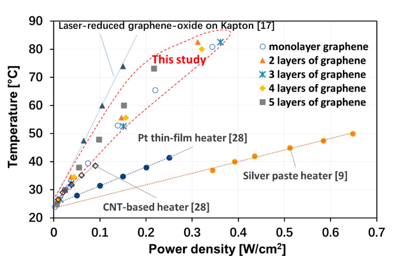
Steady-state temperature versus power density for graphene and comparison heaters (source paper, Figure 5). Reproduced from Zhang et al. (2020), CC BY 4.0.
Many graphene devices are chemically doped to reduce electrical resistance. Compounds based on gold salts, nitric acid, or other charge-transfer chemicals can increase conductivity, which means a heater can deliver a target power at a more convenient voltage. The improvement can be impressive, but the added chemistry creates another failure route. Dopants can migrate, react with ambient molecules, or slowly lose their effect.
Yong Zhang and colleagues deliberately studied undoped CVD graphene. This made the electrical performance less spectacular than the most aggressively modified films, but removed one source of uncertainty. In product development, that can be a smart trade. A slightly higher starting resistance may be preferable if the material's behavior is easier to understand and stabilize. The central question becomes whether stacking clean graphene layers can provide enough conductivity without sacrificing too much light transmission.
The Layer-by-Layer Compromise
The researchers grew monolayer graphene on copper foil and transferred it to flexible PET. Repeating the wet-transfer process created heaters with one, two, three, four, or five layers. Chromium and gold electrodes at the edges supplied current. Each added graphene sheet opened more pathways for charges, so resistance fell sharply from nearly 5 kilohms for the monolayer to roughly 1–1.5 kilohms for most multilayer samples.
But every added layer also absorbed a little more light. The reported transmission stepped down from about 97.7 percent for one layer to 87.3 percent for five. This is the core design trade-off in a form any product team can understand: clarity, voltage, and manufacturability cannot be optimized independently. A windshield may prioritize maximum transmission; a mirror or outdoor sign may accept a darker film in exchange for lower resistance and simpler power electronics.
The data were not perfectly monotonic. Four- and five-layer heaters sometimes showed higher resistance than the three-layer version. The authors suggested wrinkles, cracks, or polymer residue from repeated transfer as likely causes. Adding a theoretically ideal layer should improve conduction. Adding a real transferred layer can also add defects. More material does not automatically mean a better device.
Manufacturing Reality
The word "layer" sounds reassuringly precise, but the manufacturing reality is messier. Each transfer can improve the electrical network and simultaneously introduce a wrinkle, trapped residue, or weak patch. In other words, stacking changes both the material and the probability of defects.
A Heater Is a Balance, Not Just a Hot Film
Electrical input raises the temperature until heat leaving the device matches heat entering it. Some energy moves into the surrounding air by convection, some into the substrate and contacts by conduction, and some leaves as thermal radiation. Because graphene has low emissivity, the researchers treated radiation as relatively small and used the relationship between power density and steady temperature to estimate convective heat transfer.
For one- to four-layer devices, the average fitted coefficient was about 60 watts per square meter per degree Celsius. The paper compared this with larger values for platinum thin-film and silver-paste heaters, concluding that the graphene devices reached a greater temperature rise for a given power density in the reported setups. The trend was encouraging, but the experiment took place in a fume cupboard. Air movement probably pushed the apparent convection into the range normally associated with forced rather than natural airflow.
That context matters when moving from a 2.25-square-centimeter sample to a door-sized window. A larger surface sees changing wind, edge cooling, mounting pressure, and temperature gradients. Bus bars must distribute current without creating bright visual lines. Control electronics must prevent local overheating if part of the film becomes damaged. The material's laboratory efficiency is only the starting value in a thermal system.
Seconds to Heat — and a Model That Matched
The monolayer sample heated and cooled with an exponential response characterized by a time constant of roughly 6–7 seconds. In a representative test it stabilized at 38 degrees Celsius with 170 milliwatts of electrical input and reached about 80 degrees with 780 milliwatts. Five layers reacted more slowly, with time constants around 10 seconds for heating and 14 seconds for cooling. All are fast enough to make responsive defogging plausible on a small device.
The team also built finite-element models in COMSOL. The simulated steady temperatures for one-, three-, and five-layer heaters agreed well with experiments, and the calculated maps showed the expected increase in surface temperature with applied voltage. Modeling is especially valuable for scale-up because it lets engineers explore electrode placement, sheet resistance, substrate thickness, airflow, and damaged regions before manufacturing every prototype.
One simulation result highlights a practical advantage of stacking. At the same power density, the five-layer heater required only about half the voltage of the monolayer because its resistance was around four times lower. Since electrical power follows $P = V^{2}/R$, cutting resistance by four allows the same power at half the voltage. Whether that benefit justifies lower transparency and extra transfers depends on the application.
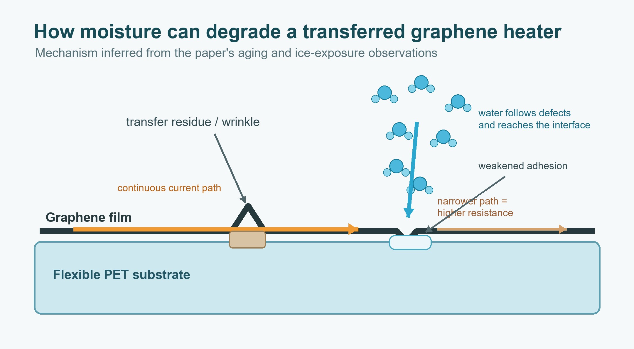
Mechanism schematic based on the paper's discussion: water may follow cracks and transfer residue to the graphene-PET interface, weakening adhesion and increasing resistance. Created for this article; not an experimental micrograph.
The Year-Long Warning
The most consequential observation arrived with time. After one year in air, resistance in some transferred graphene films increased three- to fivefold. A brief cold and wet challenge also mattered: placing the PET samples on ice raised resistance by around 10–20 percent. The value recovered after drying, suggesting that moisture and adhesion were involved rather than only permanent breakage.
A pristine graphene lattice is not likely to absorb enough water by itself to explain the whole change. The weak points are the interfaces and defects produced during fabrication. Wet transfer uses a polymer support, commonly PMMA, while the copper growth foil is removed. Even after rinsing, residue can remain. Wrinkles and microcracks create routes through which water can reach the graphene-PET boundary. Moisture may then weaken adhesion or change local electrical contact, forcing current through narrower, less reliable paths.
This is why a resistance measurement after fabrication is insufficient. A commercial qualification plan would include high-humidity storage, freeze-thaw cycling, repeated bending, powered thermal cycling, ultraviolet exposure, abrasion and cleaning tests, edge-seal challenges, and mapping of temperature uniformity after damage. It should track not only average resistance but also haze, adhesion, hot spots, contact resistance, and the energy needed to achieve a defined clearing time.
A commercial heater is only as reliable as its weakest link. Engineers therefore have to qualify the complete stack:
- the active graphene film and its resistance uniformity;
- the graphene-substrate interface and moisture barrier;
- the edge contacts, seals, and current distribution;
- the control electronics that detect drift or local overheating.
Improving Only the Graphene Is Not Enough
- Transfer residue introduces cracks and weak adhesion from the start
- Moisture exploits defects to reach the graphene-PET interface
- Resistance can rise 3–5× after one year in ambient air
- Focusing on the active layer alone can leave the dominant product failure untouched
What Has to Change Before Scale-Up
-
Improve Transfer Quality
Cleaner polymer removal, gentler handling, continuous roll-to-roll processes, and better control of copper roughness could reduce cracks and wrinkles that seed long-term degradation.
-
Add Effective Encapsulation
A thin moisture barrier above the graphene and a robust seal at the edges could slow water ingress, provided the coating stays clear and flexible. Surface treatments may improve bonding between graphene and PET, but they must not damage the carbon lattice or create optical haze.
-
Redesign Contacts for Production
The study used chromium and gold — excellent laboratory metals but not necessarily the cheapest choice for square meters of glass. Printed bus bars, conductive adhesives, and corrosion-resistant edge connectors will need to carry current evenly while staying outside the main field of view.
-
Adopt Manufacturing Metrics
Yield, defect density, sheet-resistance uniformity, optical transmission, haze, cycle life, repairability, and cost per heated area are the numbers that determine adoption. Competing technologies set moving targets.
A Fair Test Is an Application Test
The next decisive experiment would not simply compare the highest temperature reached by several films. It would place complete heater assemblies of equal visible area in the same environmental chamber, power them from realistic electronics, and ask each to clear a controlled layer of fog or ice. The comparison should hold airflow, starting temperature, substrate thickness, optical transmission, and target clearing time constant. Energy per successful clearing cycle would be more meaningful than temperature alone.
Researchers should then repeat the test after accelerated aging and after deliberate minor damage. A heater that is efficient when pristine but develops a hot stripe after a small scratch is a poor candidate for a public-facing surface. Conversely, a slightly less transparent design may win if it retains uniform heating after humidity, bending, and thousands of cycles. This system-level test would reveal whether graphene's laboratory advantage survives the compromises required for safety and durability.
FAQ about Graphene Heater Reliability
Q: Why did the researchers use undoped graphene?
Chemical doping can lower resistance, but it can also introduce substances that migrate or react with the environment. Undoped graphene provides a simpler baseline for studying the film and its interfaces.
Q: Why can humidity increase the heater's resistance?
The paper suggests that water can exploit cracks and transfer residue to reach the graphene-PET interface. Weakened adhesion or disrupted current paths can then raise resistance, although the exact mechanism needs further testing.
Q: What must a manufacturer prove before commercialization?
A product should maintain optical clarity, resistance, temperature uniformity, and safe operation after humidity exposure, bending, thermal cycling, cleaning, abrasion, and repeated powered use.
Conclusion: Graphene Heater Reliability in the Real World
The study's results remain compelling. An undoped, transparent carbon film on flexible plastic heated rapidly and uniformly, and its performance compared favorably with several metal and nanotube examples. But the year-long resistance drift and humidity sensitivity exposed the real development agenda: protecting interfaces, removing residues, designing tolerant contacts, controlling temperature, and proving durability under realistic conditions. If those problems are solved, graphene heaters could disappear into windows, mirrors, displays, lenses, and wearables — visible only through what they prevent: fog, frost, and a blocked view.
Keep Learning
How to Upgrade a 3D Printer Heated Bed with a Silicone Heater
If your 3D printer heated bed takes too long to reach temperature, develops uneven heating, or struggles to maintain a stable surface temperature, a silicone heater can be a practical upgrade. Faster warm-up and more uniform heat can improve first-layer consistency and reduce temperature-related printing issues. This guide explains how to identify when a heated-bed upgrade is needed, choose a suitable silicone heater, install it safely, and verify the results. Quick Answer A silicone heater can be a s......
How Graphene and MXene Flake Sensors Detect Force
Key Takeaways Flake networks sense force through microstructural change: Graphene and MXene coatings distribute conduction across overlapping platelets whose contacts shift under stretch or pressure, producing measurable resistance changes. Three mechanisms compete: Crack propagation, flake slippage, and quantum tunnelling each dominate at different deformation levels, giving many sensors multiple sensitivity regions rather than one uniform response. The substrate is an active partner: Elastomers, tex......
Conductive 2D Coatings Are a Matching Problem, Not a Miracle Ink
Key Takeaways Ink is a system, not a material: Conductivity depends on the combined effect of flake chemistry, solvent, additives, substrate, coating method, and post-processing—not on the 2D filler alone. Three carbon routes carry different trade-offs: GNPs demand dispersion engineering, GO shifts effort to a reduction step, and MXenes move the bottleneck to synthesis, storage, and oxidation control. Substrate geometry drives method selection: Spray and blade coating suit flat sheets; dip coating nat......
Graphene Heat Spreader Design: Layers and Interfaces
Key Takeaways Conductivity alone is not enough: A record thermal-conductivity value does not guarantee a cooler chip. Effective thickness, interface resistance, hot-spot geometry, and heat-sink connections all belong to the same thermal path. Few-layer graphene can outperform a single layer in practice: A few-layer sheet provides a larger heat-flow cross section and better tolerates transfer, embedding, and defects, even though its intrinsic conductivity is lower. Interface resistance is the bottlenec......
How Graphene Heat Spreaders Cool SOI Chip Hot Spots
Key Takeaways Buried oxide is a thermal bottleneck: SOI's insulating layer improves electrical isolation but traps heat near transistor channels, creating dangerous hot spots that package-level cooling alone cannot fix. Graphene enables lateral heat routing: Placing graphene or few-layer graphene beneath the buried oxide adds a high-conductivity sideways path, redistributing hot-spot energy toward dedicated sinks without removing any heat itself. Multi-source chips benefit most: Finite-element modelin......
Graphene Heaters Look Brilliant in the Lab. Can They Survive the Real World?
Key Takeaways Undoped graphene simplifies reliability: By avoiding chemical dopants that can migrate or degrade, undoped CVD graphene removes one failure route — though it starts with higher sheet resistance than doped alternatives. Layer stacking is a design trade-off: Each added graphene layer lowers resistance and voltage requirements but also reduces optical transmission and introduces potential transfer defects such as wrinkles and polymer residue. Durability is the real barrier: After one year i......