Flexible Conductive Coatings: Sheet Resistance, Conductivity, and Durability
16 min
- What Is a Flexible Conductive Coating?
- How Conductive Networks Work in 2D Material Coatings
- Sheet Resistance vs Conductivity: What’s the Difference?
- How Substrate Type Changes Coating Performance
- Flexibility and Bending Durability: What Really Matters
- Other Durability Factors: Adhesion, Washing, and Oxidation
- How to Compare Conductive Coatings Fairly: A Minimum Data Package
- Designing for Retained Performance, Not Peak Numbers
- Frequently Asked Questions
Sheet resistance and conductivity describe different aspects of electrical performance. Sheet resistance (Ω/sq) depends on both conductivity and film thickness, while conductivity (S/m) describes charge transport through a material volume. For a uniform thin film, Rₛ = 1/(σ × t), so thickness is essential when converting between them. Neither value alone establishes whether a flexible coating will survive bending, washing, or ageing.
This guide explains sheet resistance vs conductivity for flexible conductive coatings, how graphene- and MXene-based networks carry current, and how to compare formulations fairly across different substrates, bending conditions, and durability tests.
We cover:
1. What flexible conductive coatings are and the main material types
2. How 2D material platelets form conductive networks
3. The difference between sheet resistance and bulk conductivity
4. How substrate shape (sheet, textile, foam) changes performance
5. What bending durability actually means and how to test it
6. Other durability factors: adhesion, washing, and oxidation
7. A practical checklist for fair coating comparison
What Is a Flexible Conductive Coating?
A flexible conductive coating is a thin layer of electrically conductive material deposited on a bendable substrate such as plastic film, textile, or foam. Unlike rigid conductive layers (such as indium tin oxide on glass), these coatings are designed to maintain their electrical function when bent, stretched, or otherwise deformed.
They are used across a growing range of flexible electronics applications, including:
- Wearable sensors and smart textiles
- Flexible heaters and joule heating elements
- EMI shielding for foldable devices
- Strain and pressure sensors
- Flexible antennas and interconnects
- Energy storage components such as supercapacitor electrodes
Common Coating Material Types
Flexible conductive coatings use several material families, each with different strengths:
| Material Type | Typical Reported Value | Key Advantages | Key Limitations |
|---|---|---|---|
| Graphene / rGO | ~10⁴–10⁵ S/m (solution-processed coatings) | Excellent mechanical strength, chemical stability, large area processing | Lower conductivity than metals, dispersion challenges |
| MXenes (Ti₃C₂Tₓ etc.) | Up to ~10⁶ S/m (sheet substrates) | Highest conductivity among solution-processed 2D materials, hydrophilic | Susceptible to oxidation in humid environments |
| Silver nanowires | Sheet resistance ~30–175 Ω/sq at high optical transmittance (transparent films) | Very high conductivity, good transparency | Cost, surface roughness, potential migration |
| Conductive polymers (PEDOT:PSS) | ~10¹–10⁵ S/m (higher after secondary doping) | Solution processable, highly flexible, transparent | Lower conductivity, humidity sensitivity |
| Carbon nanotubes | Wide range depending on loading | Good mechanical compliance, bridging capability | Dispersion difficulty, purity concerns |
Values are formulation- and process-dependent literature ranges, not like-for-like rankings. Sheet resistance (Ω/sq) cannot be compared directly with conductivity (S/m) without film thickness and a suitable geometry.
This article focuses on 2D material coatings—specifically graphene-family materials and MXenes—since they have received the most research attention for flexible electronics due to their high aspect ratio, solution processability, and compatibility with large-area coating methods.
How Conductive Networks Work in 2D Material Coatings
Graphene and MXene particles are extremely thin platelets with large lateral dimensions relative to their thickness. A dried coating contains enormous numbers of these flakes. Current does not flow through the film merely because conductive material is present; it must find connected routes across overlapping platelets and their interfaces.
This is a percolating network: below a critical level of connectivity, current paths terminate and the coating is effectively insulating. Above the percolation threshold, enough contacts join to span the sample and the material becomes conductive.
Factors That Shape the Conductive Network
Several formulation and processing levers determine how well the network conducts:
- Filler loading: Higher conductive-filler content creates more contacts, but can also thicken the ink, cause aggregation, or reduce coating uniformity.
- Platelet size: Larger flakes bridge longer distances but may be harder to disperse and coat uniformly.
- Alignment: Aligned platelets make transport easier in one direction and weaker in another.
- Binder content: Binders improve cohesion and adhesion, but an electrically insulating binder sitting between flakes raises resistance.
- Drying conditions: Drying controls how closely platelets pack and whether cracks appear before testing even begins.
Hybrid Formulations
Many coatings combine a 2D material with secondary fillers such as conductive polymers, silver nanowires, carbon black, or carbon nanotubes. About 40% of the coatings surveyed in a 2022 comparative review of graphene and MXene coatings (Orts Mercadillo et al., Advanced Functional Materials) used a hybrid ink formulation.
The rationale is straightforward: one-dimensional nanotubes or nanowires can bridge gaps between separated platelets, and conductive polymers can connect irregular contacts. More components, however, also bring more interfaces, more processing variables, and additional ageing mechanisms.
Sheet Resistance vs Conductivity: What’s the Difference?
Two electrical measurements are commonly reported for conductive coatings, and they answer different questions. Understanding the distinction is essential for fair comparison.
Sheet Resistance (Ohms per Square)
Sheet resistance, measured in ohms per square (Ω/□), describes the lateral resistance of a thin film across a square area. It is the value most often cited because it is relatively easy to measure with a four-point probe.
In a four-point probe measurement, current passes through two outer contacts and voltage is sensed with two inner contacts. This arrangement reduces the influence of lead and contact resistance. When the film is much thinner than the probe spacing (a thickness-to-spacing ratio below 0.1 is a common thin-film condition) and the sample is large compared with that spacing, sheet resistance is Rₛ = (π / ln 2) × V/I ≈ 4.532 × V/I. This expression assumes four equally spaced, collinear probes on a uniform film, with the probes far from sample edges. Finite sample size, nearby edges, or other probe geometries require appropriate correction factors.
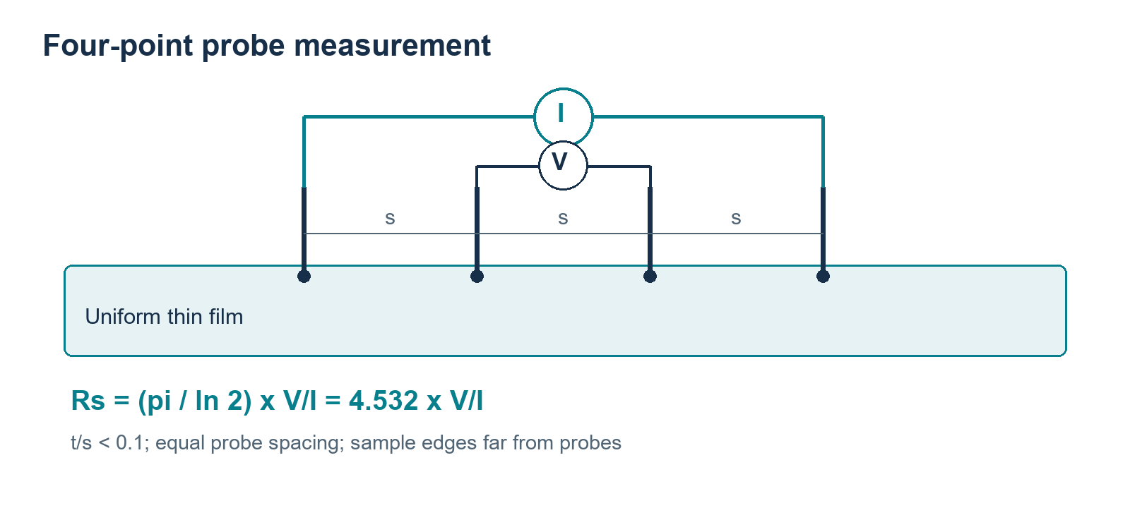
Figure 1. Four equally spaced probes on a large, uniform thin film. The outer probes supply current and the inner probes sense voltage; the ideal thin-film conversion includes the 4.532 factor.
Key property: Sheet resistance is independent of the square’s absolute side length. A 1 cm square and a 1 m square of the same film have the same sheet resistance.
Bulk Conductivity (Siemens per Metre)
Bulk conductivity (sigma, σ), measured in siemens per metre (S/m), describes how readily the material volume carries current. It is an intrinsic material property that does not depend on sample dimensions.
The Relationship and the Ambiguity
When thickness t is known and thin-film assumptions hold, sheet resistance and conductivity relate as follows:
Rₛ = 1 / (σ × t)
Where: Rₛ = sheet resistance (Ω/□), σ = bulk conductivity (S/m), t = film thickness (m)
This formula exposes a crucial ambiguity: a very conductive thin film and a less conductive thick film can report the same sheet resistance. Without thickness data, you cannot separate the intrinsic electrical quality of the material from the amount deposited.
For example, a 100 nm film with a conductivity of 10⁶ S/m and a 1000 nm film with a conductivity of 10⁵ S/m both give a sheet resistance of 10 Ω/□. Same number, very different coatings.
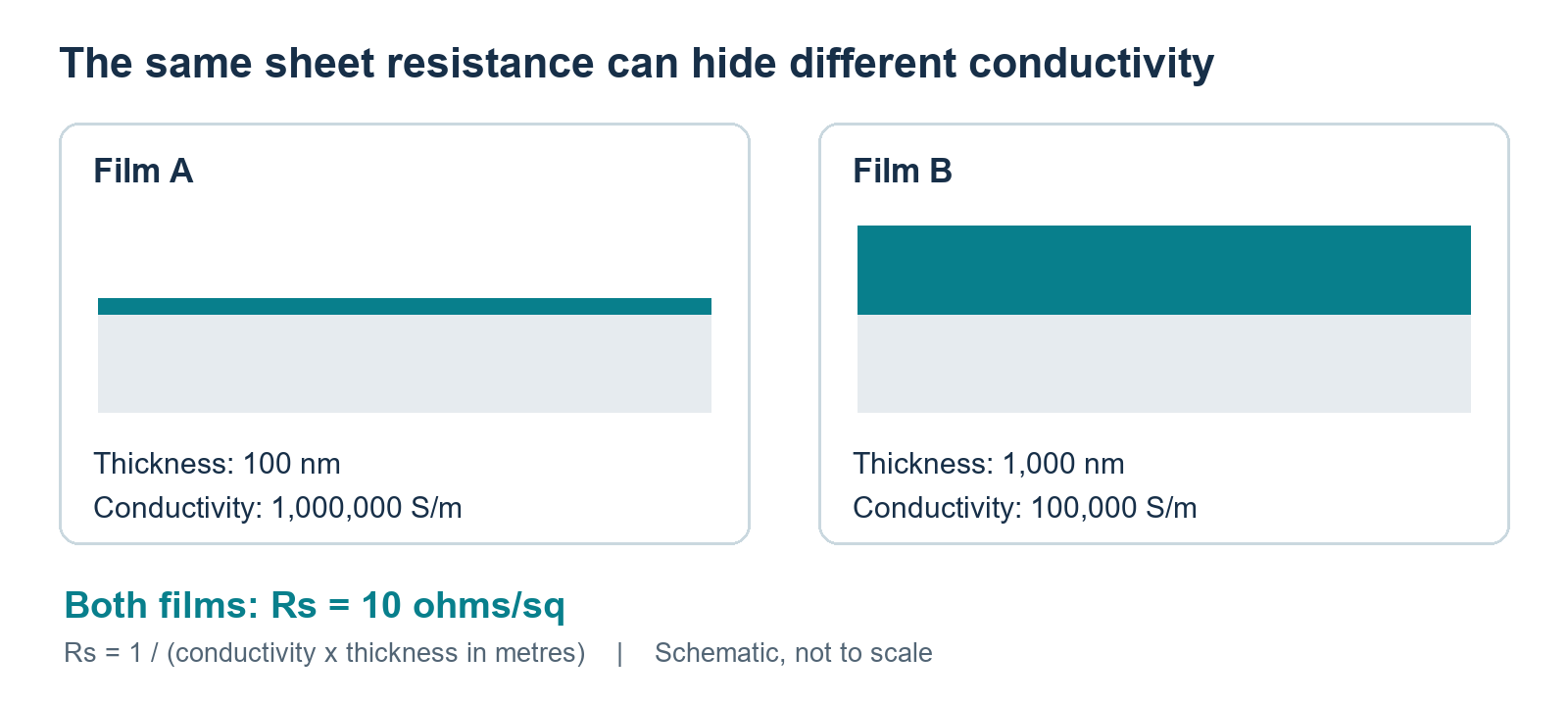
Figure 2. Two films with different conductivity and thickness both have a sheet resistance of 10 Ω/sq. Thickness is needed to convert sheet resistance into conductivity.
Geometry Complicates Things Further
The simple relationship above works best for flat, uniform films on sheet substrates. On other substrate forms, the conversion becomes unreliable:
- On textiles, ink penetrates between fibres and coats individual yarns at different depths, so the conductive volume is difficult to define.
- On foams, the structure is intrinsically three-dimensional, so bulk conductivity is a more appropriate metric than sheet resistance.
- Converting between values without a defensible geometry creates precision without meaning.
How Substrate Type Changes Coating Performance
The same conductive formulation can produce very different results depending on the substrate it is applied to. The substrate geometry fundamentally changes how the conductive network forms and how current travels through it.
Sheet Substrates (PET, PI, etc.)
A flat plastic sheet lets a deposited film connect across a relatively direct plane. If platelet surfaces are compatible with the substrate, less binder may be needed. Sheet substrates generally produce the highest measured conductivities because the current path is the most direct.
Reported benchmark: A 4.3 μm Ti₃C₂Tₓ film spray-coated on PET reached 1.2 × 10⁶ S/m, the highest value found in the review.
Textile Substrates
A textile asks the conductive network to travel around fibres, across yarn contacts, and through changing gaps. The current path is much longer and more tortuous. Warp and weft directions can also behave differently.
Reported benchmark: The most conductive textile coating in the review was an rGO coating enhanced with PEDOT:PSS, reaching 6.4 × 10⁴ S/m — roughly two orders of magnitude lower than the leading sheet result.
Foam Substrates
A foam adds tortuous three-dimensional paths and a large internal surface area. These structures can be excellent for sensing because deformation changes many contacts, but their bulk conductivity is naturally much lower.
Reported benchmark: An rGO foam with silver nanowires and polydopamine on a sea sponge template was reported at 59 S/m.
These numbers should not be read as a simple league table. They compare very different current paths and material volumes. A coating on sheet substrate and a coating on foam serve different engineering purposes.
What to Report for Fair Comparison
When comparing coatings across substrate types, always check whether the report includes:
- Substrate construction and material
- Sample dimensions and direction of current measurement
- Coating mass or thickness
- Electrode configuration and probe spacing
- Number of replicate measurements across the coated area
Flexibility and Bending Durability: What Really Matters
A flexible conductive coating must work while its conductive contacts are being rearranged. Bending puts the outer surface in tension and the inner surface in compression. Platelets may slide, separate, buckle, or reconnect.
Whether resistance change is desirable depends on the application: a strain sensor deliberately exploits the effect, while a heater, antenna, or interconnect needs stable resistance under deformation.
Bend Radius Alone Is Not Enough
Reported bend radius tells you surprisingly little about the actual mechanical state of the coating. Many other factors influence strain:
- Film position relative to the substrate’s neutral axis
- Substrate thickness and stiffness
- Bend direction (convex vs. concave)
- Bend speed, dwell time, and cycle count
- Recovery interval before measurement
A sample bent once around a large cylinder has not demonstrated fatigue resistance. Repeated loading can propagate cracks, polish or abrade contacts, and leave the network in a permanently different state after unloading.
The Standardization Problem
A widespread issue in the research literature is that many devices are electrically characterized while mechanically relaxed and are separately shown to flex or stretch. A flexible electronic component is likely to operate under deformation, so the decisive measurement is often electrical performance during load and after many load-unload cycles.
Testing in those states reveals whether a low initial resistance is robust, deliberately strain-sensitive, or simply temporary.
Other Durability Factors: Adhesion, Washing, and Oxidation
Bending is only one durability challenge. Real-world coatings must also withstand adhesion forces, repeated washing, and environmental ageing.
Adhesion
Adhesion keeps the conductive network attached as the substrate deforms. Weak adhesion can produce local lifting long before the material itself loses conductivity. Factors that influence adhesion include:
- Surface chemistry and roughness of the substrate
- Surface pretreatment (plasma, corona, chemical priming)
- Binder type and content in the formulation
The adhesion-conductivity trade-off is a central challenge: a binder may strengthen attachment and wash resistance while increasing electrical resistance between flakes. This trade-off should be mapped as a formulation series rather than hidden by reporting only the best initial specimen.
Washing Durability
Washing is a combined chemical and mechanical challenge. Water, detergent, temperature, agitation, and drying can remove loosely attached material, swell a polymer matrix, or change interfaces.
A claim of "wash durability" is incomplete without specifying:
- The washing procedure and standard followed (e.g., ISO 6330 or AATCC 135 home-laundering procedures)
- Number of wash cycles
- Temperature and detergent used
- Timing of electrical measurement (immediately after washing, after drying, after recovery)
Encapsulation may protect the conductor, but it can also stiffen the system, reduce vapour transport, and change strain transfer. The protected assembly, not the naked coating, then becomes the object that must be compared.
Oxidation and Ageing
Environmental stability is a critical but often under-reported aspect of coating durability. MXenes are particularly susceptible to oxidation, which can degrade their electrical performance significantly over time.
One study cited in the review found that Ti₃C₂Tₓ in a PVA matrix fell to 7% of its initial conductivity at 10 wt% loading and to 40% at 50 wt% loading under ambient conditions. However, oxidation rates are highly sensitive to humidity, ultraviolet exposure, applied voltage, and use frequency, so this example should not be generalized into a universal lifetime estimate.
Graphene-family coatings have different ageing risks, including aggregation and interface degradation. All coating types benefit from controlled stability studies rather than assuming long-term performance from initial measurements.
How to Compare Conductive Coatings Fairly: A Minimum Data Package
Comparability improves when every electrical result travels with enough context to reconstruct the test. A concise minimum data package can be added to a figure caption, table, or data record. It will not eliminate differences between laboratories, but it makes them visible and prevents the reader from treating non-equivalent samples as identical.
Essential Information Checklist
| Category | What to Report | Why It Matters |
|---|---|---|
| Formulation | 2D material identity, co-fillers, binder/stabilizer, proportions | Determines intrinsic conductivity and network structure |
| Substrate | Form, material, dimensions, coating method | Affects current path and effective conductive volume |
| Electrical result | Sheet resistance or conductivity AND thickness / coating mass | Allows material quality vs. amount comparison |
| Measurement setup | Electrode configuration, probe spacing, sample geometry, environment, specimen count | Enables independent verification and comparison |
| Durability protocol | Bend / wash / thermal / ageing procedure, cycle count | Defines the stress level being compared |
| Resistance timing | Measured during stress, immediately after, or after recovery | Different timings answer different engineering questions |
| Performance retention | Retained performance, drift, and variability (not just best initial value) | Reveals long-term usability, not just peak performance |
Application-Specific Criteria
On top of this foundation, application-specific criteria should be added. The same starting sheet resistance can be acceptable for one role and unusable for another:
- Joule heaters: Need stable temperature at a stated voltage under bending. This is why production flexible heaters still use etched metal foil laminated in polyimide or silicone rubber: the foil holds its resistance through bending and thermal cycling far more predictably than a coated network. See where graphene heaters stand today.
- EMI shielding: Need attenuation at a stated thickness and frequency while deformed.
- Strain sensors: Deliberately change resistance but must do so repeatably and predictably.
- Transparent electrodes: Must balance sheet resistance with optical transmittance.
Designing for Retained Performance, Not Peak Numbers
There is genuine promise in graphene and MXene coatings: their high aspect ratio supports connected networks, solution processing can reach large areas, and established coating routes can address sheets, fabrics, and porous forms.
However, laboratory samples often omit packaging and encapsulation, while long-term stability receives less attention than initial performance. Scaling a coating also changes drying, handling, and defect statistics, so a strong coupon is evidence of possibility rather than manufacturing readiness.
The most informative design target is retained function under a defined service profile. That target may accept a slightly higher initial resistance in exchange for better adhesion, lower drift, or simpler aqueous processing. It may favour a thicker coating if mass and flexibility allow, or a hybrid network if added complexity produces measurable durability gains.
Sheet resistance remains a useful tool. It becomes an engineering result only when the coating’s thickness, structure, deformation, and history are attached to the number.
Frequently Asked Questions
Why can two coatings with the same sheet resistance behave differently?
Sheet resistance combines material conductivity with conductive-layer thickness. A thin, highly conductive film can match a thicker, less conductive one. Platelet contacts, binder content, uniformity, and substrate geometry can also differ, so bending, heating, or ageing may separate two samples that look equivalent initially.
What is the difference between sheet resistance and conductivity?
Sheet resistance (Ω/□) measures the lateral resistance of a thin film and depends on both material conductivity and film thickness. Bulk conductivity (S/m) is an intrinsic material property that does not depend on dimensions. The relationship is Rₛ = 1/(σ × t), meaning you need thickness to convert between them.
What is the most useful durability test for a flexible coating?
Use the stress that matches real service: bending for a folded interconnect, washing for a textile, or controlled humidity and storage for an oxidation-sensitive film. Define strain or bend radius, cycle count, environment, and measurement timing, then report resistance both during stress and after recovery.
Does adding a binder always improve coating durability?
No. A binder can improve cohesion, adhesion, and resistance to handling, but an insulating binder may separate conductive platelets and raise resistance. It can also change flexibility, moisture uptake, and ageing. The useful formulation is a measured compromise between electrical connectivity and retained mechanical integrity.
What are the main materials used in flexible conductive coatings?
The main material families are graphene-family materials (graphene, rGO), MXenes (Ti₃C₂Tₓ and others), silver nanowires, conductive polymers (PEDOT:PSS), and carbon nanotubes. Many practical formulations combine two or more of these for hybrid performance.
Why do MXene coatings degrade over time?
MXenes are susceptible to oxidation, particularly in humid environments. Oxygen and water can react with the MXene surface, converting conductive titanium carbide into insulating titanium oxide. The rate depends on humidity, temperature, UV exposure, flake size, and whether the material is encapsulated or composite-buffered.
What applications use flexible conductive coatings?
Flexible conductive coatings are used in wearable sensors, smart textiles, flexible heaters, EMI shielding, strain sensors, flexible antennas, supercapacitor electrodes, and transparent electrodes for foldable displays and touch sensors.
What is the four-point probe method?
The four-point probe is the standard technique for measuring sheet resistance. It uses four equally spaced contacts: current is passed through the two outer probes, and voltage is measured across the two inner probes. This configuration largely removes the influence of contact resistance and lead resistance, giving a more accurate measurement than a two-point method.
Keep Learning
Flexible Conductive Coatings: Sheet Resistance, Conductivity, and Durability
Sheet resistance and conductivity describe different aspects of electrical performance. Sheet resistance (Ω/sq) depends on both conductivity and film thickness, while conductivity (S/m) describes charge transport through a material volume. For a uniform thin film, Rₛ = 1/(σ × t), so thickness is essential when converting between them. Neither value alone establishes whether a flexible coating will survive bending, washing, or ageing. This guide explains sheet resistance vs conductivity for flexible co......
How Graphene and MXene Inks Enable Stretchable Circuits
Stretchable circuits must maintain electrical performance while bending, stretching, or twisting. Graphene and MXene inks offer a promising approach by combining electrical conductivity, mechanical flexibility, and printability. But how do these materials actually enable circuits to stretch without losing their electrical function? Graphene and MXene inks enable stretchable circuits by forming interconnected conductive networks that can rearrange as the substrate deforms. Their overlapping 2D platelet......
Graphene vs MXene Inks for Flexible Electronics: Which Is Better?
GNP, GO, rGO, and Ti3C2Tx MXene all share a platelet shape, but they differ dramatically in conductivity, water compatibility, production scale, and shelf life. If you're designing flexible electronics, choosing the right 2D material ink means understanding which trade-offs your device can tolerate. In this guide, we compare the four most common 2D material inks side by side—graphene nanoplatelets (GNP), graphene oxide (GO), reduced graphene oxide (rGO), and Ti3C2Tx MXene—and explain when each one mak......
What Is a Thermoelectric Generator and How Does It Work?
Can heat from an engine, industrial process, or other heat source be turned into useful electricity without moving parts? A thermoelectric generator (TEG) does this by converting a temperature difference directly into electrical power through the Seebeck effect. Its power output depends on the temperature difference across the device, the thermoelectric materials, and the overall system design. What Is a Thermoelectric Generator? A thermoelectric generator (TEG) is a solid-state device that converts h......
What Are Flexible Electronics? How They Work & Where They're Used
Flexible electronics are electronic circuits, devices, and systems designed to maintain their intended functions while bending or conforming to a surface. They enable electronic functions to fit curved, moving, lightweight, or space-constrained products. Common examples include flex circuits in cameras and phones, wearable sensors, flexible heaters, flexible displays, RFID and NFC labels, conformal industrial sensors, and medical patches. Flexible electronics is a broad field that encompasses differen......
What Is a Strip Heater? How It Works: A Complete Guide [2026]
Strip heaters are electric resistance heaters commonly used to heat metal surfaces, machinery, and industrial equipment. Their flat, narrow design allows them to be mounted against surfaces or in spaces where other heater shapes may be less suitable. Understanding how strip heaters are constructed and installed helps determine whether they’re the right choice for a particular heating application. What Is a Strip Heater? A strip heater converts electrical energy into heat through a resistance element h......