
Flexible Heater Design Tutorial with JLCPCB Calculator Tool
17 min
- Introduction
- Electrical Circuit Design
- Material Selection
- Summary
This tutorial is specifically designed for JLCPCB's flex heater customization service. We provide a dedicated calculator tool that simplifies the complex trace design process, allowing you to focus on performance parameters while our engineers handle the technical implementation.
Click here to download the Excel file!
Introduction
In this article, I'll explain how to design a flex heater from the perspectives of material selection and electrical design. I believe every electronics DIY enthusiast is somewhat dissatisfied with commercial products on the market and hopes to have greater freedom over product parameters to customize their own designs. However, when you actually start customizing, you can easily encounter a dilemma: whether you're a beginner just starting out in electronics or an experienced maker facing a new component, you might find yourself lost in various parameters, not knowing what each parameter does or how to adjust them to achieve the desired effect.
Fortunately, flex heaters are not overly complex components. While they offer customization opportunities, they are much simpler compared to more fundamental components like PCBs. This single article can cover the main design points. It's important to note that the flex heaters discussed in this article specifically refer to flexible heating films, not other flexible heating products like heated water tubes.
Electrical Circuit Design
The core of a flex heater is its circuit trace design. Traditional trace design is quite complex, requiring consideration of resistance distribution, heat uniformity, trace spacing, and many other factors, making it challenging for beginners. The good news is that JLCPCB has designed a calculator tool specifically for beginners to calculate key design parameters, bypassing the complex trace layout work. This means you can focus on performance parameter design, while the specific trace implementation can be handled by our professional engineers. Below, I'll explain in detail how to use this calculator tool.
Tool Interface Overview
This tool is an Excel spreadsheet (we will launch online versions and other formats later). The entire spreadsheet is functionally divided into three core areas:
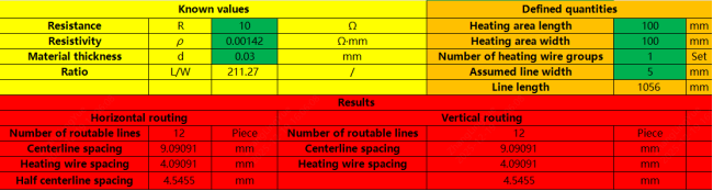
Central calculation area, green cells require manual input, red parts show calculation results
Material parameter area, containing materials available for heating wires
Calculation verification area, used to verify results from the central calculation area
Understanding the function of these three areas is key to using the tool. Simply put, the central calculation area is your main workspace, the material parameter area provides physical parameters of different metal materials for reference, and the calculation verification area helps you confirm the accuracy of your design.
Step-by-Step Design Process
Step 1: Prepare Basic Parameters
First, we need to fill in three fundamental parameters in the central calculation area:
1. Heating area length
2. Heating area width
3. Target resistance (Resistance R)
Length and width can be directly measured from the area you need to heat. If it's not a regular geometric shape, you can approximate it with a rectangle that covers the area. The resistance value needs to be calculated based on your project's supply voltage and power requirements. For example, if your project uses 12V power supply and you want 14.4W of power, then according to the formula R = V²/P, the resistance should be set to 10Ω.
In our example, assume the project's heating area is 100mm × 100mm with a target resistance of 10Ω, as shown filled in the image.
Step 2: Select Heating Material
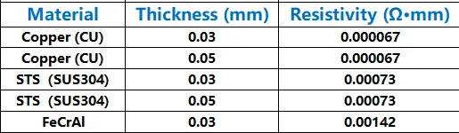
Next, you need to select a heating metal material. In the material parameter area, you can see parameters for several common materials, mainly including:
● Material thickness
● Resistivity
Fill these two parameters of the selected material into the central calculation area. In the example, we chose FeCrAl (Iron-Chromium-Aluminum alloy).
Basic principles for material selection:
● If the target resistance is high (e.g., tens of ohms or more), choose high-resistivity materials like FeCrAl
● If the target resistance is low (e.g., a few ohms), choose low-resistivity materials like Copper
This makes the trace design more reasonable and avoids traces that are too narrow or too wide.
Step 3: Set Number of Wire Groups
The "Number of heating wire groups" parameter represents the number of parallel circuits in the flex heater. This is an important design variable:
● More groups means increased total conductor cross-sectional area, resulting in lower resistance
● Fewer groups means higher resistance, but simpler trace routing
If you're unsure how to set this, it's recommended to start with 1 and adjust based on subsequent calculation results.
Step 4: Iterative Line Width Optimization
This is the most critical step in the entire design process. You need to input an initial value in "Assumed line width" and then observe the calculation results.
Specific procedure:
1. Enter a value in the "Assumed line width" cell (recommended to keep one decimal place, such as 0.5, 1.0, etc.)
2. Press Enter to let the spreadsheet calculate
3. Observe the "Line width" parameter in the calculation results area
4. Compare the difference between "Assumed line width" and "Line width"
Optimization goal: Make these two values as close as possible. When the difference is within 2, it's an acceptable design result.
Note that the relationship between these two parameters is not linear, so you need to try different values multiple times. If you cannot get them close no matter how you adjust, you need to return to step two or three and try changing materials or adjusting the number of wire groups.
This iterative process may require several attempts, but typically you won't need more than 5 tries to find a suitable parameter combination.
Step 5: Design Verification
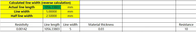
After confirming the assumed line width, we need to perform final verification in the calculation verification area to ensure design accuracy.
Verification steps:
1. Fill in "Resistivity" in the verification area—consistent with the material selected in step two
2. Fill in "Material thickness"—also consistent with material parameters
3. Fill in the "Assumed line width" value just calculated in "Line width"
4. Fill in the actual line length in "Line length". Note that you should fill in "Actual line length" here, as in actual production, factors like pad positions and trace corners may cause slight variations in line length
5. Press Enter and check the calculated resistance value
If the calculated resistance value matches the target resistance you set in the central calculation area (or the error is within 5%), congratulations—this design is feasible! You can submit these parameters to engineers for trace design and production.
If the verification result differs significantly from the target, you need to return to step four to readjust parameters or check for input errors.
Material Selection
After completing the electrical design, let's discuss material selection. Many beginners tend to overlook the importance of material selection, believing that as long as the circuit design is correct, everything will be fine. However, material selection directly determines the flex heater's service life, application scenarios, safety performance, and cost. With the same electrical design but different materials, the final product performance can vary dramatically.
The heating principle of flex heaters is very simple—they use resistive heating, essentially the same as heating modules in common appliances like hair dryers and space heaters. However, the resistance wires in these appliances are too thick and large, not thin or flexible enough to meet flexible heating needs. Therefore, we use metal materials with higher resistivity and better malleability, so that a small amount of metal wire can generate the required heat while maintaining the film's flexibility.
A complete flex heater product consists of the following components:
1. Heating resistance wire: The core component that provides heat
2. Encapsulation film: A film material that wraps the resistance wire, providing insulation protection and structural support
3. Lead wires: Conductors connecting to external power
4. Temperature sensor (optional): Monitors and controls temperature
5. Adhesive layer: Usually 3M strong double-sided tape, used to fix to the heated object's surface
Based on this structure, we can see that when designing a flex heater, there are three main component materials that can be freely selected: encapsulation film, heating resistance wire, and backing adhesive. Let's analyze the characteristics and selection recommendations for these materials one by one.
Encapsulation Film: Silicone vs PI
The most easily identifiable feature from appearance is the encapsulation film material. The encapsulation film not only affects the product's appearance but, more importantly, directly impacts the flex heater's temperature resistance, mechanical strength, flexibility, and usage scenarios. Therefore, people usually name different flex heater products directly by their encapsulation material, such as PI heater (Polyimide heating film) and Silicone heater.
The two most commonly used encapsulation materials on the market are Silicone and PI (Polyimide). Below is a comparison of typical parameters for flex heaters made from these two materials:
| Property | PI Flex Heater | Silicone Flex Heater |
| Base Material Thickness | 0.09-0.27mm | 1.0-2.0mm (including silicone layer) |
| Light Transmittance | 50μm PI film: 60.2%25μm PI film: 70.6% | 0% |
| Temperature Range | -40~260℃ (long-term <150℃) | -40~300℃ (long-term <200℃) |
| Voltage Range | 3.7~220VAC 2000VDC1min leakage ≤1mA | 1~380VAC 2500VDC1min leakage ≤1mA |
| Insulation Resistance | ≥100MΩ @DC 1000V | ≥500MΩ @DC 1500V |
| Maximum Power Density | 1.0 W/cm² | 2.0 W/cm² |
| Thermal Conductivity | 0.2-0.35 W/(m·K) | 1.0-1.5 W/(m·K) |
| Mechanical Compressive Strength | ≤50KG/cm² | 200KG/cm²≤, ≤350KG/cm² |
| Wire Pull Force | ≥100N | ≥100N |
| Service Life | 5 years | 5 years |
| Solder Joint Pull Force | ≥40N | ≥40N |
From this comparison table, we can clearly see the differences and respective advantages of the two materials:
PI Flex Heater Characteristics:
● Ultra-thin design: Base material thickness only 0.09-0.27mm, 1/5 to 1/10 of silicone film, can easily conform to various complex curved surfaces
● Good light transmittance: 50μm thick PI film can achieve over 60% light transmittance, suitable for applications requiring transparency
● Excellent flexibility: If you have experience processing FPC (Flexible Printed Circuits), you're familiar with PI material. Its flexibility is extremely strong and can be repeatedly bent without damage
● Fast heat conduction: The relatively thin thickness allows faster heat transfer and rapid temperature rise
Application scenarios: PI flex heaters are typically used in precision equipment with protective housings, such as medical devices (like blood warmers), heating systems for new energy vehicle battery packs, heating modules in massage devices, laboratory instruments, etc. These application scenarios share the common feature that the flex heater itself is not directly exposed to harsh environments, with the housing providing additional physical protection.
Silicone Flex Heater Characteristics:
● High compressive strength: Mechanical compressive strength can reach 200-350KG/cm², 4-7 times that of PI film, very durable
● Higher temperature range: Can withstand higher instantaneous temperatures, more reliable in extreme environments
● Better insulation performance: Insulation resistance reaches over 500MΩ, providing higher safety
● Higher power density: Can reach 2.0 W/cm², twice that of PI film, suitable for applications requiring rapid high-power heating
Application scenarios: Silicone flex heaters are often used in exposed or direct-contact scenarios, such as pipe freeze protection heating, tank heating, outdoor equipment heating, food processing, etc. Its thick film layer itself provides sufficient protection and is not easily damaged by external forces.
Selection recommendations:
● If your application requires ultra-thin, flexible design that can conform to complex surfaces and has protective housing, choose PI
● If it needs to be directly exposed or withstand greater pressure and harsh environments, choose Silicone
● For high power density heating requirements, Silicone is the better choice
● From a cost perspective, PI film is typically slightly more expensive than equivalent-area silicone film
Heating Metal Wire: Copper / Stainless Steel / FeCrAl
The heating metal wire is the "heart" of the flex heater, and its material directly determines the electrical performance. We've already encountered parameters for these materials in the electrical design section; now let's understand their characteristics more deeply.
| Material | Thickness (mm) | Resistivity (Ω·cm²) |
| Copper (CU) | 0.03 | 0.067 ± 6% |
| Copper (CU) | 0.05 | 0.067 ± 6% |
| Stainless Steel (SUS304) | 0.03 | 0.768 ± 6% |
| Stainless Steel (SUS304) | 0.05 | 0.768 ± 6% |
Although the table only lists copper and stainless steel, there's actually a third commonly used material—Iron-Chromium-Aluminum alloy (FeCrAl), which has even higher resistivity, approximately 1.2-1.4 Ω·mm²/m.
Copper (CU):
● Lowest resistivity: 0.067 Ω·cm², meaning the same resistance value requires thinner and longer traces
● Excellent thermal conductivity: Heat distribution is more uniform
● Application scenarios: Suitable for low-resistance, high-current designs, commonly used in low-voltage power supply applications (such as 5V, 12V)
Stainless Steel (SUS304):
● Medium resistivity: Over 10 times that of copper, providing more flexible trace design
● Strong corrosion resistance: Suitable for humid or chemical environments
● High mechanical strength: Not easily broken
● Application scenarios: Medium resistance value designs, or applications requiring operation in harsh environments
Iron-Chromium-Aluminum Alloy (FeCrAl):
● Highest resistivity: About 1.5-2 times that of stainless steel, suitable for high-resistance designs
● Excellent high-temperature performance: Can withstand higher working temperatures
● Strong oxidation resistance: Does not easily age during long-term high-temperature use
● Application scenarios: High-resistance, high-temperature applications, such as industrial heating, applications requiring 220V power supply
Selection recommendations:
● Choose based on the resistance value calculated from electrical design: low resistance choose copper, high resistance choose FeCrAl, medium values choose stainless steel
● Consider supply voltage: low-voltage (≤24V) systems typically use copper, high-voltage (≥110V) systems are more suitable for stainless steel or FeCrAl
● Consider working environment: humid, corrosive environments prioritize stainless steel; high-temperature environments prioritize FeCrAl
● From cost perspective: Copper < Stainless Steel < FeCrAl
Backing Adhesive: 3M Model Comparison
The backing adhesive is key to fixing the flex heater to the heated object's surface. Good adhesive must not only stick firmly but also withstand high temperatures and aging, maintaining stable adhesion performance throughout the service life. 3M is the leading brand in this field. Below is a comparison of several commonly used models:
| Tape Model | Thickness (mm) | Long-term Temperature | Short-term Temperature | Low Temperature Limit | Features & Application Scenarios |
| 3M 9448A | 0.15 | 70℃ | 150℃ | - | General-purpose black/white double-sided tape, suitable for medium-low temperature applications, non-structural component fixing |
| 3M 468MP | 0.13 | 149℃ | 204℃ | -35℃ | High-performance acrylic adhesive, strong high-temperature/chemical resistance, recommended for PI flex heaters, metal bonding surfaces |
| 3M 55236 | 0.06 | 70℃ | 150℃ | - | White thin double-sided tape, suitable for light-duty bonding, compatible with low-power flex heaters |
| Crown 513 (Domestic) | 0.16 | 80℃ | 110℃ | - | Domestic alternative, thick and elastic, suitable for curved or rough surfaces, obvious price advantage |
Characteristics and selection recommendations for each adhesive model:
3M 9448A - General Economy Type
● Most common industrial-grade double-sided tape, available in black and white
● Medium temperature resistance (long-term 70℃, short-term 150℃), suitable for most medium-low temperature applications
● Relatively low cost, high cost-effectiveness
● Application scenarios: Flex heaters with low power density (<0.5 W/cm²), applications with working temperatures not exceeding 60℃, non-structural load-bearing components
● Precautions: Not suitable for high-temperature environments; adhesion force will significantly decrease above 70℃
3M 468MP - High-Performance Recommended Type
● High-performance acrylic pressure-sensitive adhesive, the preferred backing for flex heater applications
● Excellent high-temperature resistance (long-term 149℃, short-term 204℃), can handle most heating scenarios
● Good chemical resistance and anti-aging properties, long service life
● Application scenarios: Standard configuration for PI flex heaters, metal surface bonding, applications requiring long-term operation above 80℃
● Recommendation reason: Although slightly more expensive, it offers comprehensive performance and high reliability, making it standard for professional products
3M 55236 - Ultra-thin Precision Type
● Ultra-thin design (0.06mm), adds almost no thickness
● Suitable for precision applications with strict thickness requirements
● Relatively lower adhesion force, suitable for light-duty applications
● Application scenarios: Low-power flex heaters (<10W), applications requiring extreme thinness, such as wearable devices, small medical devices
● Precautions: Not suitable for large-area or heavy-duty applications, requires very flat bonding surfaces
Crown 513 - Domestic Alternative
● Domestic brand with outstanding cost-effectiveness
● Thick and elastic (0.16mm), good adaptability to rough or slightly curved surfaces
● Medium-low temperature resistance (long-term 80℃, short-term 110℃)
● Application scenarios: Budget-limited projects, situations where bonding surfaces are not flat enough, applications without high temperature requirements
● Precautions: Quality stability slightly inferior to 3M products, recommended for non-critical applications
General precautions for adhesive use:
1. Surface preparation: Clean the bonding surface before application, removing grease, dust, and other contaminants. Isopropyl alcohol (IPA) can be used for wiping
2. Pressure application: After bonding, apply pressure (recommended 15 PSI, about 1 kg/cm²) for at least 15 seconds to ensure full contact between adhesive and surface
3. Cure time: Avoid high stress for 24 hours after bonding; adhesion force reaches maximum after 72 hours
4. Temperature matching: When selecting adhesive, its temperature resistance range should be at least 20℃ higher than the flex heater's actual working temperature
5. Curved surface bonding: For curved surfaces, it's recommended to choose thicker, softer adhesives (like Crown 513) or use additional mechanical fixing methods
Mechanical Fixing Methods
In addition to backing adhesive, there are various mechanical fixing methods, mainly seen in Silicone heaters, including:
● Spring hooks: Suitable for cylindrical objects (such as pipes, barrels, etc.)
● Bolt fixing holes: Installation holes with metal reinforcement strips reserved at flex heater edges
● Velcro: Removable temporary fixing solution
● Metal clips: Suitable for applications requiring frequent disassembly
The purpose of these mechanical fixing methods is to firmly secure the flex heater to the heated object. Especially for objects like barrels and pipes that are frequently moved, relying solely on backing adhesive may not be secure enough and may fall off over time, requiring additional mechanical fixing.
Selection recommendations:
● Stationary applications (such as battery pack internal heating): Backing adhesive is sufficient
● Occasionally moved equipment (such as portable instruments): Quality backing adhesive + edge mechanical reinforcement
● Frequently moved or vibration environments (such as transport barrels, pipes): Mechanical fixing as primary, backing adhesive as secondary
● Applications requiring regular maintenance and disassembly: Velcro or removable hook systems
Important Notice: The above mechanical fixing methods are for technical reference only
It should be noted that JLCPCB currently only provides backing adhesive installation solutions. The spring hooks, bolt fixing holes, Velcro, and metal clips mentioned above are to help you understand installation choices in different application scenarios, allowing you to make more suitable judgments based on actual needs.
If you do need mechanical fixing methods, consider:
1. Adding mechanical reinforcement measures on top of the backing adhesive solution
2. Choosing thicker backing adhesive products (like Crown 513) to increase installation reliability
3. Discussing customized solutions with the JLCPCB technical support team during the design phase
It's recommended to clarify installation method requirements in the early stages of your project so we can provide the most suitable customized solution for you.
Summary
Designing a flex heater (flexible heating film) involves two major aspects: electrical design and material selection. However, after mastering the methods and tools introduced in this article, the process is not complicated.
In terms of electrical design, through the calculator tool provided by JLCPCB, you can easily complete parameter optimization without diving into complex trace layouts. The key is understanding the meaning of each parameter, mastering iterative optimization methods, and ultimately ensuring design accuracy through verification.
For material selection, remember these core principles:
● Encapsulation film: Need ultra-thin and flexible? Choose PI. Need durable and robust? Choose Silicone
● Metal wire: Low resistance choose copper, high resistance choose FeCrAl, medium values choose stainless steel
● Backing adhesive: Match working temperature, high-temperature applications must use 468MP, limited budget can choose 9448A or domestic alternatives
Most importantly, design based on actual application scenarios:
● Clarify power supply voltage and power requirements
● Understand working environment (temperature, humidity, mechanical stress, etc.)
● Consider cost budget and mass production feasibility
● Reserve safety margins, especially for temperature and power
I hope this tutorial helps you successfully design flex heater products that meet your requirements. If you encounter problems during actual operation, feel free to consult JLCPCB's technical support team—our engineers will provide professional guidance and optimization suggestions.
Remember: Good design comes from deep understanding of requirements and meticulous attention to detail. Best wishes for your project's success!
Keep Learning
Flexible Heater Design Optimization: Why We Use Rounded Corners and Teardrops
TL;DR: Those sleek curves and "teardrops" you see on flexible heater circuits aren't just for looks. They are critical engineering features that: Prevent Cracking: Rounded corners distribute physical stress during thermal expansion, stopping metal fatigue and micro-cracks. Even Out Heat: Smooth paths prevent electrical "hotspots" that occur at sharp 90-degree angles. Boost Durability: Teardrops act like mechanical tendons, strengthening fragile solder connections against pulling and bending. Improve M......
How to Choose Temperature Control for Custom Flexible Heating Films
So, you're designing a custom heating solution—perhaps a heated jacket, a 3D printer bed, or a specialized medical device. You've picked out your heating film material, but now you face a critical question: How do I stop this thing from getting too hot? Selecting the right temperature control is just as important as the heating element itself. It's the difference between a cozy, efficient device and a melted, hazardous mess. But with terms like "NTC," "Bi-metal," and "Hysteresis" thrown around, it can......
Custom Flexible Heater Case Study: From JLC PCB Order to Performance Validation
Introduction Flexible heaters represent a paradigm shift in modern heating technology, redefining our approach to thermal management in electronic systems. The evolution from traditional rigid resistive heating elements to PCB-based flexible heating solutions marks a significant leap toward high-precision, high-reliability manufacturing. This comprehensive guide explores the technical principles, material engineering, design methodologies, and practical applications of flexible heaters, providing engi......
Flexible Heater Design Tutorial with JLCPCB Calculator Tool
This tutorial is specifically designed for JLCPCB's flex heater customization service. We provide a dedicated calculator tool that simplifies the complex trace design process, allowing you to focus on performance parameters while our engineers handle the technical implementation. Click here to download the Excel file! Introduction In this article, I'll explain how to design a flex heater from the perspectives of material selection and electrical design. I believe every electronics DIY enthusiast is so......
3D Printer Bed Heating Upgrade: How to Replace Your Silicone Heater
In the world of 3D printing, the extruder often gets all the glory, but seasoned makers know the truth: a successful print starts with the first layer. Friends living in colder climates might recognize this scene: it’s winter in the garage, the room temperature has plummeted, and you are shivering next to your printer, waiting endlessly for the bed to heat up. Or perhaps your "old reliable" machine, which has clocked hundreds of printing hours, is starting to show signs of uneven heating. Just like ca......
Factors Affecting Heating Film Uniformity: A Guide for Efficient Thermal Management
Resistive heating elements, particularly in thin, flexible forms known as heating films, have become the backbone of modern efficient thermal management. Their ability to deliver controllable, uniform heat within compact devices makes them indispensable in industries ranging from aerospace to medical tech. However, simply applying power to a resistive circuit does not guarantee performance. Achieving consistent temperature distribution in a flexible heater requires a deep understanding of circuit layo......