
Billet Heating and End Heating by Induction: Uniformity, Throughput, and Coil Strategy
11 min
- Fundamentals of Induction Heating for Steel Billets
- Coil Design Strategies for Uniform Heating
- Electromagnetic and Thermal Phenomena Affecting Heating Uniformity
- Power Distribution and Process Control
- Summary Checklist for Induction Billet Heating
- FAQ about Induction Billet Heating
Key Takeaways
Temperature Targets: Steel billets require heating to 1050°C–1260°C with surface-to-core uniformity within ±20°C to ±30°C for quality forging outcomes.
Frequency Matters: Billet diameter dictates frequency selection—higher frequencies (>30 kHz) for small billets, lower frequencies (<500 Hz) for large billets—to optimize heating depth and uniformity.
Profiled Coils Outperform: Variable-pitch, graded coils deliver superior temperature uniformity and shorter coil lengths compared to conventional uniform coils, despite higher manufacturing complexity.
End Effects Require Compensation: Electromagnetic end effects and thermal edge effects cause localized temperature variations at billet ends; coil design, overhang, and power distribution must counterbalance these phenomena.
Dynamic Control Is Essential: Advanced numerical modeling, real-time monitoring, and dynamic power redistribution enable adaptive process control for consistent heating across varying billet sizes and materials.
Induction heating (IH) of steel billets is a critical process in modern metal forming industries, where billets must be heated uniformly and efficiently to temperatures that enable plastic deformation via forging, extrusion, or rolling. Achieving precise temperature control throughout the billet volume—both radially and axially—is essential to ensure material quality, process reliability, and equipment longevity. This article delves into the technical aspects of billet heating and end heating by induction, focusing on temperature uniformity, throughput optimization, and coil design strategies that address the complex electromagnetic and thermal phenomena involved.
Fundamentals of Induction Heating for Steel Billets
Steel billets are typically heated to temperatures ranging from approximately 1050°C to 1260°C, depending on their chemical composition and the requirements of subsequent hot working processes. The target temperature uniformity is stringent, commonly within ±20°C to ±30°C, both from surface to core and along the billet length. Achieving this uniformity is challenging due to the interplay of electromagnetic field distribution, heat conduction, radiation losses, and the physical movement of billets through the induction coil system.
The frequency of the induction power supply is a key parameter influencing heating depth and uniformity. Smaller billets (e.g., diameters less than 13 mm) require higher frequencies, often exceeding 30 kHz, to concentrate heating near the surface. Larger billets (diameters around 0.2 m or 8 inches and above) are heated at lower frequencies, sometimes below 500 Hz, to allow deeper penetration of induced currents and more uniform internal heating.
Two primary heating modes are employed in billet induction heating:
- Progressive Heating: Billets move sequentially through one or multiple coils, receiving staged heating.
- Static Heating: Billets remain stationary within the coil during the heating cycle.
This article primarily focuses on progressive heating, which is prevalent in industrial applications.
Coil Design Strategies for Uniform Heating

Conventional vs. Profiled (Graded) Coils
1Conventional Coils
The induction coil design profoundly affects the temperature distribution within billets. Traditional coils feature uniform winding pitch and consistent copper tubing dimensions along their length. While simpler to manufacture, these coils often require longer lengths to achieve desired heating profiles and may not optimize surface-to-core temperature gradients.
2Profiled (Graded) Coils
Profiled or graded coils, by contrast, employ variable winding pitch and tubing dimensions along the coil length. The initial and intermediate coil sections have tighter windings and narrower copper tubing, increasing current density and inducing higher surface power density. This accelerates heating in the billet's outer layers, promoting rapid radial heat flow toward the core during early heating stages.
In the final coil section, windings are looser and tubing wider, reducing power density to avoid overheating the surface once it reaches the target temperature. This staged approach balances rapid heating with controlled soak times, improving temperature uniformity and reducing thermal gradients that can cause cracking, especially in high-carbon or alloy steels.
The fabrication of profiled coils is more complex and labor-intensive, requiring precise control of winding parameters. Additionally, the risk of excessive surface-to-core temperature gradients during initial heating necessitates careful process control and may require multiple coil sets to accommodate low-toughness materials.
- Winding Pitch
Uniform along entire length
- Manufacturing
Simpler and less labor-intensive
- Coil Length
Longer coils needed for desired profiles
- Temperature Control
Limited optimization of gradients
- Winding Pitch
Variable pitch and tubing dimensions
- Manufacturing
More complex, precise control required
- Coil Length
Shorter coils achieve same results
- Temperature Control
Superior uniformity with staged heating
Coil Change and Twin Track Systems
Industrial billet heating lines often need to accommodate a range of billet sizes and materials, necessitating coil changes to optimize heating efficiency and temperature uniformity. Minimizing downtime during coil changeover is critical to maintaining throughput.
Twin track coil systems provide an effective solution by housing multiple coil assemblies on parallel tracks with a common base. This design enables rapid switching between coil sets aligned with the billet feed path, reducing changeover time to minutes and eliminating the need for offline coil storage. Twin track systems enhance operational flexibility and maximize system availability.
Electromagnetic and Thermal Phenomena Affecting Heating Uniformity
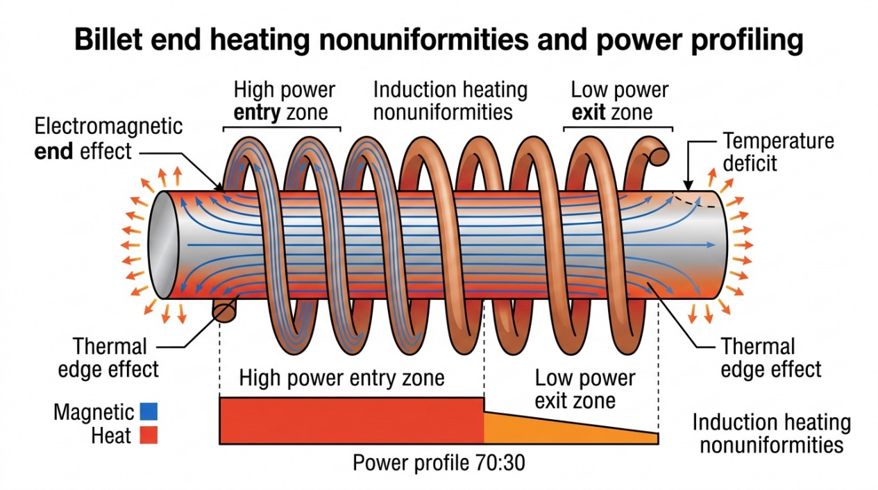
Electromagnetic End Effects
Electromagnetic End Effects
The magnetic field distribution at the ends of billets is influenced by the electromagnetic end effect, which arises from the finite length of the ferromagnetic workpiece within the coil. At the tail end of a billet, the magnetic field intensity may decrease, causing localized heat deficits.
When billets are positioned end-to-end with minimal axial gaps, the interaction of their electromagnetic properties further complicates the field distribution. For example, a billet heated above its Curie temperature becomes essentially nonmagnetic (relative permeability μr ≈ 1), altering the magnetic coupling with adjacent billets still below the Curie point. This difference can cause increased power density at the trailing end of the hotter billet and decreased power density at the leading end of the cooler billet, partially compensating for initial temperature nonuniformities.
Thermal Edge Effects
Thermal radiation losses at billet ends are governed by Lambert's cosine law, which states that radiative heat flux depends on the angle of emission relative to the surface normal. The shape and surroundings of the billet influence these losses, causing the thermal edge effect.
At the leading end of a billet, especially during the final heating stage when surface temperatures are high, radiative losses are significant. This can result in a local heat deficit despite electromagnetic power surpluses induced by coil design. Proper selection of coil overhang, frequency, and power distribution is necessary to counterbalance thermal edge effects and maintain axial temperature uniformity.
Axial Heat Flow Between Adjacent Billets
Heat transfer along the billet axis occurs through the contact surfaces between adjacent billets. However, surface roughness, oxide scales, and air gaps introduce substantial thermal resistance, limiting conduction.
Two primary heat transfer mechanisms at billet interfaces are:
- Conduction through solid-to-solid contact points: Limited by microscopic contact area.
- Heat flow through air pockets: Air's low thermal conductivity imposes high resistance.
Engineering Note
Axial heat flow between billets is generally negligible for forging applications and can often be omitted from thermal models. When necessary, thermal contact resistance methods can estimate this transfer.
Power Distribution and Process Control
Power Profiling Along the Coil Length
Induction heating lines typically distribute power unevenly along the coil length to optimize temperature gradients and internal heat flow. Common heuristics include the 60:40 or 70:30 power distribution rules, where the entering half of the coil receives 60–70% of the total power, and the exiting half receives the remainder.
This approach intensifies heating early in the billet's path, generating a strong radial heat flow toward the core. The reduced power in the latter half maintains surface temperature and compensates for heat losses, promoting uniform soak and minimizing thermal gradients.
Important
The 60:40 and 70:30 power distribution rules are generalized heuristics and may not suit all billet sizes or materials. Power distribution must be tailored to specific process requirements and billet properties.
Subsurface Overheating and Cracking Risks
A critical challenge in induction billet heating is avoiding subsurface overheating, which can lead to cracking, premature die wear, and compromised product quality. Surface pyrometers provide limited information, measuring only localized surface temperatures and potentially missing internal temperature anomalies.
Subsurface overheating often manifests as localized heat surpluses beneath the surface, which cannot be detected without advanced modeling. Conversely, heat deficits can cause cold spots that affect deformation behavior.
To mitigate these risks, modern induction heating systems integrate advanced numerical simulation tools employing finite element, finite difference, or boundary element methods. These models predict detailed temperature distributions within billets, enabling optimized coil design, power profiling, and process control strategies.
Simulation outputs can be incorporated into programmable logic controllers (PLCs) to dynamically adjust power levels and billet feed rates, ensuring consistent thermal conditions tailored to each production run.
Process Flexibility and Dynamic Power Redistribution
Induction billet heaters must accommodate variations in billet size, material composition, and production throughput. Static power distribution schemes may not provide sufficient flexibility, leading to inefficiencies or quality issues.
Dynamic power redistribution, guided by real-time temperature monitoring and model predictions, allows adaptive control of coil power levels. This approach minimizes energy consumption, reduces thermal gradients, and enhances throughput without sacrificing uniformity.
Implementing such control requires sophisticated hardware and software integration, including multi-inverter power supplies, segmented coil circuits, and advanced sensors.
Throughput Considerations and Heating Time
Heating time depends on billet size, material properties, and target temperature. Smaller billets may require only seconds, while large billets can take several minutes to reach forging temperatures.
Optimizing throughput involves balancing heating rate with temperature uniformity and equipment constraints. Excessive heating rates can induce thermal stresses and cracking, while slow heating reduces productivity.
Progressive heating with profiled coils and power profiling enables rapid initial heating followed by controlled soak, maximizing throughput while preserving billet integrity.
Summary Checklist for Induction Billet Heating
- Target billet temperatures typically range from 1050°C to 1260°C, with surface-to-core uniformity within ±20°C to ±30°C.
- Frequency selection depends on billet diameter: higher frequencies (>30 kHz) for small billets, lower frequencies (<500 Hz) for large billets.
- Profiled (graded) coils with variable winding pitch and tubing dimensions improve heating uniformity and reduce coil length compared to conventional coils.
- Electromagnetic end effects and thermal edge effects cause localized temperature variations at billet ends; coil design and power distribution must compensate accordingly.
- Axial heat flow between adjacent billets is generally negligible due to high thermal contact resistance.
- Power distribution along the coil length follows heuristics like 60:40 or 70:30 rules but should be customized based on billet properties and process needs.
- Subsurface overheating risks necessitate advanced numerical modeling and temperature monitoring beyond surface pyrometry.
- Dynamic power redistribution and multi-inverter coil circuits enhance process flexibility and uniformity.
- Twin track coil systems facilitate rapid coil changeover, minimizing downtime and supporting diverse billet sizes.
- Heating time optimization balances rapid temperature rise with uniformity to maximize throughput and prevent material damage.
FAQ about Induction Billet Heating
Q: Why do different billet sizes require different heating frequencies?
Frequency selection depends on the penetration depth needed. Smaller billets (under 13 mm diameter) use higher frequencies (above 30 kHz) to concentrate heating near the surface, while larger billets (around 200 mm or 8 inches) require lower frequencies (below 500 Hz) to allow deeper current penetration and more uniform internal heating throughout the volume.
Q: What are profiled coils and why are they better than conventional coils?
Profiled (or graded) coils use variable winding pitch and copper tubing dimensions along their length. The initial sections have tighter windings for higher power density to rapidly heat the surface, while final sections have looser windings to prevent overheating. This staged approach achieves better temperature uniformity and shorter coil lengths compared to conventional uniform coils, though they're more complex to manufacture.
Q: Why is subsurface overheating a concern and how is it addressed?
Subsurface overheating can cause cracking and quality issues but cannot be detected by surface pyrometers alone. It occurs when heat accumulates beneath the surface due to improper power distribution. Modern systems address this through advanced numerical modeling (finite element analysis) that predicts internal temperature distributions, enabling optimized coil design, power profiling, and dynamic control adjustments to prevent these hidden thermal problems.
Conclusion: Induction Billet Heating and Coil Strategy
Induction heating of steel billets demands a sophisticated balance of electromagnetic design, thermal management, and process control. From selecting the right frequency for the billet diameter to implementing profiled coils and dynamic power redistribution, every aspect of the system must be optimized to achieve the stringent temperature uniformity required for high-quality metal forming. By leveraging advanced simulation tools, real-time monitoring, and flexible coil systems, modern induction heating lines can deliver consistent, efficient, and reliable billet heating for diverse production requirements.
Keep Learning
How Transparent Graphene Heaters Clear Fogged Glass
Key Takeaways Atom-thin transparency: A single graphene layer transmits about 97.7% of visible light, while five stacked layers still pass roughly 87.3%, making the heater nearly invisible on glass or plastic. Fast, controllable heating: A monolayer device reaches its target temperature with a thermal time constant of only about 6–7 seconds, and input power can be adjusted to hold temperatures from 38 °C up to around 80 °C. Efficiency advantage: Graphene heaters achieved higher temperatures at the sam......
Process Control, Monitoring, and Quality Assurance in Induction Heating: Reducing Risk Without Cutting Every Part
Key Takeaways Separate control from monitoring: A control system executes the recipe; a monitoring system independently verifies what actually happened. Independence turns logs into evidence. Monitor intermediate variables: You can't measure fatigue strength inline, but you can measure delivered kW, frequency stability, position, and quench variables—then compare each cycle to a validated "good envelope." Signature monitoring beats single thresholds: Time-series signatures capture ramps, holds, and tr......
Cooling Induction Power Supplies: Designing the Thermal System That Protects Your Electrical System
Key Takeaways Cooling is a first-class subsystem: Many "electrical" failures in induction lines are actually thermal problems—drifting water temperature, clogged filters, or unbalanced branch flow. Measure at the branch, not the header: A healthy header can mask a starved branch. Branch flow to the highest-loss modules is the single most useful cooling measurement. Trend cooling like a process variable: Baseline flow, temperature, and filter pressure drop during commissioning, then trend them to turn ......
Independent Frequency and Power Control in Induction Inverters: Turning Frequency Back Into a Process Variable
Key Takeaways Frequency as a process variable: Independent frequency and power control decouples resonance supervision from kW regulation, letting engineers set frequency based on process physics rather than control mechanics. Measurable validation: Prove independent control with three commissioning tests—fixed-frequency power steps, fixed-kW frequency sweeps, and coupling variation stability. Production consistency: Stable frequency improves recipe portability, reduces hidden process changes, and mak......
Simultaneous Dual-Frequency Induction Heating: When One Frequency Forces the Wrong Compromise
Key Takeaways One frequency, one compromise: When geometry demands both deep bulk heating and controlled surface gradients simultaneously, a single frequency forces an unacceptable trade-off—dual-frequency widens the process window. Give each channel a role: Assign the lower frequency to bulk penetration and the higher frequency to surface shaping. Structured recipe development follows naturally from this separation. Validate with metrics, not opinions: Dual-frequency is justified only when controlled......
Power Supplies by Application Family: Joining, Mass Heating, and Strip Processing
Key Takeaways Joining operations (brazing, soldering, bonding) demand higher frequencies and matching flexibility to handle variable coil coupling and precision surface heating. Mass heating lines (billets, bars, slabs) prioritize continuous duty, efficiency, and ruggedness at high power levels with multi-coil zone control. Strip processing requires architectures that separate control electronics from high-frequency inverter modules to cope with harsh installation environments. Specifying only kW and ......