How Graphene and MXene Flake Sensors Detect Force
11 min
- When a Flake Network Feels a Touch
- Resistance Is the Readout, Not the Whole Mechanism
- Three Ways a Flake Network Changes
- Stretch Pulls Pathways Apart; Pressure Builds Them Up
- The Substrate Is an Active Component
- Why Hybrids Can Broaden the Useful Range
- The Sensitivity Trap
- Durability Means Returning to the Same Electrical Story
- Designing the Network Around the Question
- FAQ about Graphene and MXene Piezoresistive Flake Sensors
Key Takeaways
Flake networks sense force through microstructural change: Graphene and MXene coatings distribute conduction across overlapping platelets whose contacts shift under stretch or pressure, producing measurable resistance changes.
Three mechanisms compete: Crack propagation, flake slippage, and quantum tunnelling each dominate at different deformation levels, giving many sensors multiple sensitivity regions rather than one uniform response.
The substrate is an active partner: Elastomers, textiles, and foams each shape how force reaches the conductive network, influencing sensitivity, range, recovery, and durability.
Headline gauge factors can mislead: Record sensitivity numbers are meaningless without the strain interval, linearity, hysteresis, cyclic stability, and environmental conditions under which they were measured.
Design starts with the mechanical question: The best sensor is the one whose response stays interpretable throughout the required range and lifetime, not the one with the largest isolated number.
When a Flake Network Feels a Touch
Graphene and MXene coatings can turn stretch, pressure, and motion into measurable resistance changes. Their promise comes not from an unbreakable conductor, but from carefully controlling how thousands of tiny electrical contacts separate, slide, crack, and reconnect.
A conventional strain gauge is designed to change resistance predictably when it deforms. That becomes difficult when the surface beneath it is soft, porous, woven, or expected to stretch far beyond the limits of metal.
Networks of conductive two-dimensional flakes offer a different strategy. Rather than asking one solid track to survive every motion, they distribute conduction across many overlapping platelets. Graphene-based materials and MXenes are especially interesting because their thin, broad shapes create a large number of contacts within a coating. Mechanical force changes those contacts, and the electrical resistance records the change.
The sensor must change enough to be sensitive, but not so much that its conductive network fails. It must also cover the required range and return to a stable baseline after repeated use.
Resistance Is the Readout, Not the Whole Mechanism
A piezoresistive sensor converts mechanical deformation into a change in electrical resistance. For a strain sensor, performance is often summarized by the gauge factor:
$$GF = \frac{\Delta R / R_0}{\varepsilon}$$
Here, ΔR is the resistance change, R0 is the resistance before deformation, and ε is strain: the fractional change in length. A larger gauge factor means a larger electrical response for the same strain. Pressure sensors use a related sensitivity measure, commonly expressed per kilopascal, because the input is force divided by area rather than extension.
These numbers are useful only alongside the range over which they apply. A device can be extremely sensitive within a narrow interval and unusable outside it; another may tolerate far greater strain but produce a modest response. Many sensors have multiple sensitivity regions because different mechanisms dominate as deformation increases.
Linearity matters too. A straight, repeatable relationship makes conversion easy; a curve that changes slope requires multiple calibration regions or a more complicated model. The real task is to balance sensitivity, range, linearity, recovery, and durability.
Three Ways a Flake Network Changes
Imagine a conductive coating as a crowded floor covered with playing cards. Current can move across individual cards and from one overlapping card to the next. Stretching or compressing the floor changes the overlaps and the gaps between them. In a real sensor, three mechanisms contribute.
Crack propagation opens microscopic breaks in the conductive layer and removes current pathways. Resistance can rise sharply, enabling high sensitivity, but continued crack growth can disrupt the network, limit range, and leave permanent damage.
Slippage and disconnection occur when overlapping flakes or coated fibres move past one another. Conduction may survive greater extension than in a crack-dominated film, but larger deformation may be needed for a strong response.
Tunnelling operates across extremely small insulating gaps. Its probability is highly sensitive to separation distance, so a small packing change can alter resistance. Once gaps become too large, the contribution rapidly fades.
Two-dimensional flakes can participate in all three processes. Their high aspect ratio — wide compared with their thickness — creates extensive overlaps, while edges, junctions, and voids still respond to force. The coating is not a uniform resistor; it is a changing map of possible routes.
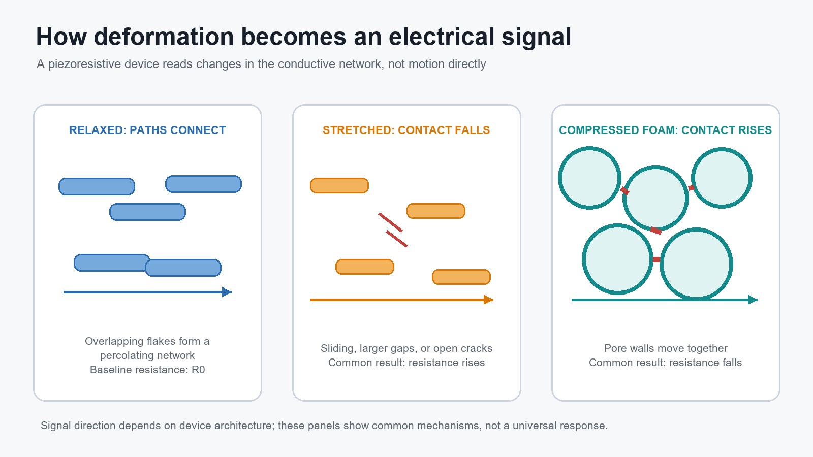
Common ways that relaxed, stretched, and compressed flake networks change resistance. Explanatory diagram based on the source discussion. Created for this article; not an experimental image.
Stretch Pulls Pathways Apart; Pressure Builds Them Up
Under tension, adjacent flakes, coated fibres, or pieces of a porous skeleton generally move farther apart. Overlap decreases, tunnelling gaps widen, and cracks open. The number of viable current paths falls, so resistance usually increases.
Under compression, pores collapse, coated surfaces meet, and neighbouring flakes move closer together, so resistance usually decreases. Pressure sensors can exploit both the conductive film and electrode contact. In one reviewed MXene-coated cotton device, different pressure ranges emphasized contact resistance and resistance within the coated textile.
Not every response follows a single direction from the start. A graphene-and-carbon-nanotube coating on polyurethane sponge, for example, showed a slight resistance increase at low pressure as microcracks expanded. Beyond 2.7 kPa, compression brought the coated foam skeleton into closer contact and resistance dropped substantially. The example shows why a device's response curve must be measured rather than assumed from a simple "compression equals lower resistance" rule.
A sensor can therefore have several linear regions: light loading may improve electrode contact, while higher loading activates pore collapse or flake rearrangement. A slope change signals a new mechanical regime.
The Substrate Is an Active Component
The conductive material receives much of the attention, but the substrate decides how external force reaches the flake network. It sets the shape of deformation, influences recovery, and provides the surface to which the coating must adhere.
Elastomer sheets such as latex or polyurethane offer controlled geometry and large extension. They help restore the conductive layer after release, but flat films can concentrate strain in cracks, making adhesion and encapsulation critical.
Textiles provide yarns, fibres, and contact points that separate or rotate under strain. This creates many opportunities for resistance to change, helping explain their popularity for strain sensing. Dip-coating can cover fibres over a large area without complex patterning.
Foams and sponges are useful for pressure sensing because their pores deform gradually and recover after release. Their stiffness tunes the pressure range, while their large internal surface hosts the coating. Under compression, coated struts form new contacts: the substrate acts as both spring and contact generator.
A foam optimized for gentle touch may saturate under body weight. A textile may be sensitive to direction, weave, humidity, or washing. A sheet may be easier to model but less conformable.
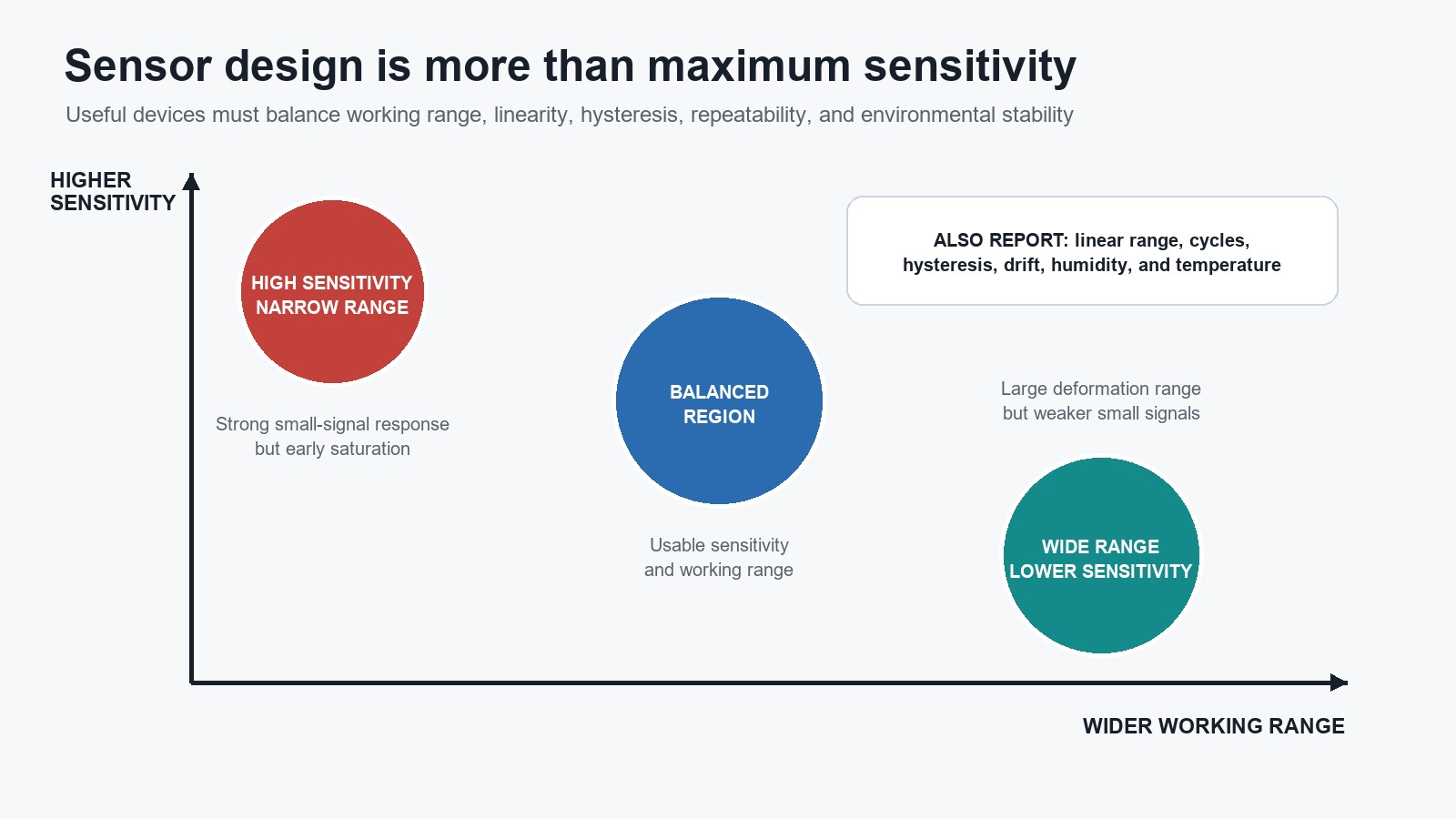
Sensitivity and working range are only two parts of a broader sensor-design trade-off. Explanatory diagram based on the source discussion. Created for this article; not an experimental image.
Why Hybrids Can Broaden the Useful Range
One material rarely supplies every desirable behavior. Hybrid networks combine fillers with different shapes so that one component remains conductive while another produces a strong mechanical response.
A reviewed sensor made from alternating MXene and carbon-nanotube layers on latex illustrates the logic. MXene platelets made the network responsive to crack formation at low strain, while nanotubes acted as conductive bridges and helped prevent platelet restacking. The device reported a gauge factor of 4.35 between 0.1% and 0.6% strain and 772.6 between 30% and 70% strain. Those values do not describe one uniform response; they describe different regimes within a deliberately mixed network.
Another design combined graphene oxide, silver nanowires, and fullerene particles. The nanowires supplied a conductive framework, while the fullerene addition reportedly suppressed severe cracking and promoted sliding. The mixture redistributed how damage developed.
A bridge-like filler can preserve current paths when platelets separate, while small particles or binders modify friction, packing, or crack growth. The possible gain is a wider range; the cost is a microstructure more sensitive to composition, dispersion, and processing.
The Sensitivity Trap
It is tempting to compare flexible sensors by their largest gauge factor. That can be deeply misleading.
The review found a broad trade-off: many devices achieved either high sensitivity over limited strain or large stretchability with lower sensitivity. Crack propagation explains much of this pattern. The earliest crack opening can create a steep resistance change, but continued cracking can destroy the percolating network. Sliding contacts remain viable over greater motion, yet they often change resistance more gradually.
An extreme example makes the point. A graphene-and-carbon-black coating on notched cotton reported a gauge factor of 102,351 between 342% and 400% strain. But the fabric was "rupture trained" through five cycles at 400% strain, cracking and completely fracturing yarns at the notch before characterization. The exceptional response came from the motion of deliberately broken, tentacle-like fibre ends.
That result is an ingenious demonstration of a particular substrate-driven mechanism. It is not evidence that graphene coatings in general provide six-figure gauge factors, nor does it establish broad durability, linearity, or manufacturing consistency. Without the strain interval and rupture history, the headline number tells the wrong story.
A Fair Comparison Should Ask
- Over what exact range was sensitivity calculated?
- Is the response linear within that range?
- How large is hysteresis between loading and unloading?
- Does the baseline recover after repeated cycles?
- Was the device tested while bent, stretched, humid, washed, or otherwise used as intended?
- How variable are nominally identical samples?
Durability Means Returning to the Same Electrical Story
A sensor can survive mechanically and still drift electrically. Repeated loading may move flakes into new positions, deepen cracks, alter fibre contacts, or change adhesion between the coating and substrate. The unloaded resistance can shift, and the same applied strain can produce a different signal on the next cycle. This history-dependent difference is hysteresis.
Substrate recovery does not guarantee reconstruction of the original network. Encapsulation can reduce abrasion and improve resistance to washing, ultraviolet exposure, and humidity, but may stiffen the device. Durability is part of sensing performance, not a separate packaging issue.
The review calls for more cyclic testing, recovery measurements, reproducibility, and operation under real deformation. It also notes that research has outpaced standardization, making results from different geometries and protocols difficult to compare.
For practical design, the winning sensor will probably not be the one with the largest isolated sensitivity. It will be the one whose response remains interpretable throughout the pressure or strain range that matters, after the number of cycles the application demands, in the environment where it must operate.
Designing the Network Around the Question
The most productive starting point is not "graphene or MXene?" It is the mechanical question the sensor must answer.
A gentle-touch sensor needs sensitivity before its pores saturate. A joint sensor needs range and cycling tolerance. A pressure array needs consistent pixels and manageable contact resistance. A textile interface may value washability more than a record gauge factor.
Once that target is clear, the flake chemistry, filler geometry, coating method, substrate, electrodes, and encapsulation can be treated as one coupled system. Graphene and MXene networks are valuable because their many junctions make resistance highly responsive to microstructural change. The same feature also makes them sensitive to processing variation and mechanical history.
That is the central paradox of piezoresistive flake sensors: the network must be allowed to come apart, but only in a controlled and repeatable way.
FAQ about Graphene and MXene Piezoresistive Flake Sensors
Q: What is the difference between a strain sensor and a pressure sensor?
A strain sensor measures deformation such as extension or compression relative to the original length, while a pressure sensor measures force applied over an area. Both can use piezoresistive flake networks, but strain sensitivity is often reported as gauge factor and pressure sensitivity is commonly reported in kPa-1.
Q: Why do flexible sensors often have several sensitivity ranges?
Different microstructural events dominate at different loads. Initial pressure may improve electrode contact, moderate deformation may change tunnelling gaps or flake overlap, and larger deformation may collapse pores or propagate cracks. Each regime can produce a different slope in the resistance-response curve, requiring separate calibration.
Q: Are graphene and MXene piezoresistive sensors ready for practical use?
They show strong potential, but laboratory sensitivity alone is insufficient. Practical devices need reproducible manufacturing, stable calibration, low hysteresis, environmental protection, and cyclic testing under realistic deformation. Substrate variability, coating adhesion, MXene oxidation, packaging, and the lack of fully harmonized test methods remain important engineering challenges.
Conclusion: How Graphene and MXene Flake Sensors Detect Force
Graphene and MXene flake networks offer a compelling platform for flexible piezoresistive sensing, but their real-world value depends on far more than peak gauge factor. The interplay of crack propagation, flake slippage, and tunnelling — shaped by the substrate, filler geometry, and encapsulation — determines whether a sensor delivers reliable, interpretable data across its intended range and lifetime. Designing an effective sensor means starting with the mechanical question and engineering the entire system to answer it repeatably.
Keep Learning
How to Upgrade a 3D Printer Heated Bed with a Silicone Heater
If your 3D printer heated bed takes too long to reach temperature, develops uneven heating, or struggles to maintain a stable surface temperature, a silicone heater can be a practical upgrade. Faster warm-up and more uniform heat can improve first-layer consistency and reduce temperature-related printing issues. This guide explains how to identify when a heated-bed upgrade is needed, choose a suitable silicone heater, install it safely, and verify the results. Quick Answer A silicone heater can be a s......
How Graphene and MXene Flake Sensors Detect Force
Key Takeaways Flake networks sense force through microstructural change: Graphene and MXene coatings distribute conduction across overlapping platelets whose contacts shift under stretch or pressure, producing measurable resistance changes. Three mechanisms compete: Crack propagation, flake slippage, and quantum tunnelling each dominate at different deformation levels, giving many sensors multiple sensitivity regions rather than one uniform response. The substrate is an active partner: Elastomers, tex......
Conductive 2D Coatings Are a Matching Problem, Not a Miracle Ink
Key Takeaways Ink is a system, not a material: Conductivity depends on the combined effect of flake chemistry, solvent, additives, substrate, coating method, and post-processing—not on the 2D filler alone. Three carbon routes carry different trade-offs: GNPs demand dispersion engineering, GO shifts effort to a reduction step, and MXenes move the bottleneck to synthesis, storage, and oxidation control. Substrate geometry drives method selection: Spray and blade coating suit flat sheets; dip coating nat......
Graphene Heat Spreader Design: Layers and Interfaces
Key Takeaways Conductivity alone is not enough: A record thermal-conductivity value does not guarantee a cooler chip. Effective thickness, interface resistance, hot-spot geometry, and heat-sink connections all belong to the same thermal path. Few-layer graphene can outperform a single layer in practice: A few-layer sheet provides a larger heat-flow cross section and better tolerates transfer, embedding, and defects, even though its intrinsic conductivity is lower. Interface resistance is the bottlenec......
How Graphene Heat Spreaders Cool SOI Chip Hot Spots
Key Takeaways Buried oxide is a thermal bottleneck: SOI's insulating layer improves electrical isolation but traps heat near transistor channels, creating dangerous hot spots that package-level cooling alone cannot fix. Graphene enables lateral heat routing: Placing graphene or few-layer graphene beneath the buried oxide adds a high-conductivity sideways path, redistributing hot-spot energy toward dedicated sinks without removing any heat itself. Multi-source chips benefit most: Finite-element modelin......
Graphene Heaters Look Brilliant in the Lab. Can They Survive the Real World?
Key Takeaways Undoped graphene simplifies reliability: By avoiding chemical dopants that can migrate or degrade, undoped CVD graphene removes one failure route — though it starts with higher sheet resistance than doped alternatives. Layer stacking is a design trade-off: Each added graphene layer lowers resistance and voltage requirements but also reduces optical transmission and introduces potential transfer defects such as wrinkles and polymer residue. Durability is the real barrier: After one year i......