
Mastering PCB Stiffeners: A Comprehensive Guide to Types, Applications, and Design Best Practices for Flexible Circuits
7 min
- Introduction: What Are PCB Stiffeners and Why They Matter
- Types of PCB Stiffeners: Choosing the Right Material
- Key Applications of Stiffeners in PCB Design and Assembly
- Design and Manufacturing Considerations for PCB Stiffeners
- Benefits and Best Practices for Implementing Stiffeners
- Conclusion
- FAQ: Common Questions About PCB Stiffeners
Flexible and rigid-flex PCBs are increasingly common in modern electronic designs, but their soft nature poses mechanical reliability challenges, especially in connector, component mounting, and dynamic bending areas. PCB stiffeners serve as localized reinforcement materials to effectively address these issues. They add rigidity in designated areas to provide mechanical support while maintaining bendability in flexible zones. Engineers widely use them in consumer electronics, medical devices, automotive electronics, and wearables to ensure stability under repeated insertion, vibration, or high-temperature conditions.
Introduction: What Are PCB Stiffeners and Why They Matter
The Role of Stiffeners in Flexible and Rigid-Flex PCBs
PCB stiffeners are typically non-conductive materials (such as FR4, polyimide, or metal) bonded to specific positions on the flexible substrate using pressure-sensitive adhesive (PSA) or thermal bonding. They do not participate in circuit functions but primarily enhance local rigidity to prevent pad lift-off, component displacement, or failures from excessive bending. In rigid-flex boards, stiffeners are often used in transition zones to smooth the structural change from rigid to flexible, avoiding stress concentration. In practical designs, stiffeners can be attached single- or double-sided, with thickness precisely controlled to match connector insertion depth or assembly requirements.
Evolution and Growing Demand in Modern Electronics
As component pitches shrink below 0.4 mm and product volumes decrease, flexible PCB usage has surged. Industry data shows that stiffener application in high-reliability flex circuits can reduce mechanical failure risk by 40-60%, particularly in vibration or thermal cycling environments. This has made stiffeners essential rather than optional, especially in smartphones, laptop foldable screens, and medical implants. Demand also stems from the widespread adoption of automated assembly—stiffeners provide flat platforms to improve SMT placement accuracy and reflow yield.
Types of PCB Stiffeners: Choosing the Right Material
FR4 Stiffeners – Cost-Effective and Widely Used
FR4 stiffeners are the most common type, made from glass-fiber reinforced epoxy resin, offering excellent rigidity and cost advantages. Thickness typically ranges from 0.1 mm to 3.2 mm (common 0.8 mm, 1.6 mm), with Tg values of 130-170°C. They suit most SMT component support and PTH connector reinforcement scenarios due to high mechanical strength to withstand assembly pressure, while being low-cost and ideal for high-volume production.
Polyimide (PI) Stiffeners – High-Temperature and Dynamic Flexibility
Polyimide stiffeners have chemical properties similar to flexible substrates (like Kapton), providing excellent thermal stability and flexibility. Thickness generally 0.025 mm to 0.2 mm, temperature resistance over 250°C. They are particularly suitable for ZIF connectors or gold finger areas, enduring tens of thousands of dynamic bends without cracking. In high-temperature reflow or operating environments, PI stiffeners' low CTE matches the substrate, reducing delamination risk.
Metal Stiffeners (Stainless Steel and Aluminum)
Metal stiffeners offer the highest strength and heat dissipation. Stainless steel thickness 0.1-0.5 mm, corrosion-resistant, suitable for harsh mechanical environments; aluminum thickness 0.2-1.0 mm, lightweight with high thermal conductivity (~200 W/m·K). They are often used in power modules or grounding-required areas but require insulation treatment (e.g., adding insulating layer) to avoid shorts.
| Material | Thickness Range (mm) | Key Properties | Thermal Resistance | Cost Level | Common Applications |
| FR4 | 0.1 - 3.2 | High rigidity, low cost, easy processing | Medium (Tg 130-170°C) | Low | SMT support, general reinforcement, PTH connectors |
| Polyimide (PI) | 0.025 - 0.2 | Flexible, high-temp compatible, low CTE | High (>250°C) | Medium | ZIF connectors, dynamic areas, gold fingers |
| Stainless Steel | 0.1 - 0.5 | High strength, corrosion resistant | Excellent | High | Harsh environments, vibration protection |
| Aluminum | 0.2 - 1.0 | Lightweight, high thermal conductivity | Excellent | Medium-High | Thermal management, power component heat sinking |
Table 1: Comparison table of common PCB stiffener materials.
Key Applications of Stiffeners in PCB Design and Assembly
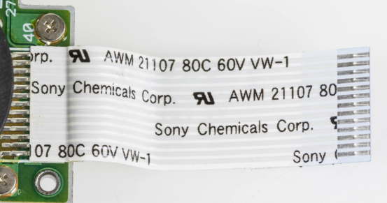
Reinforcing Connector Areas and ZIF Interfaces
In gold fingers or ZIF tails, stiffeners add local thickness (usually matching connector slot requirements of 0.3-1.0 mm) to prevent pad lift-off or substrate deformation from repeated insertion. PI stiffeners are most common here, precisely controlling thickness tolerance (±0.05 mm) for reliable contact and reduced insertion force stress.
Supporting SMT Components During Assembly
Flexible substrates easily deform during pick-and-place and reflow; stiffeners provide rigid platforms to support heavier components (like connectors, ICs, or capacitors). This improves placement accuracy, reduces offsets or tombstoning, especially in double-sided assembly where stiffeners balance stress, boosting overall yield by 10-20%.
Stress Relief and Mechanical Protection in Dynamic Environments
Stiffeners limit bend radius (recommended minimum = 10 times stiffener thickness), protecting solder joints from fatigue failure. In automotive or industrial equipment, they absorb vibration energy to extend product life.
Heat Dissipation and Thickness Control
Metal stiffeners effectively conduct heat, suitable for LED or power chip areas. They also precisely control ZIF insertion thickness for compatibility.
Design and Manufacturing Considerations for PCB Stiffeners
Attachment Methods – PSA vs. Thermal Bonding
Pressure-sensitive adhesive (PSA) requires no heat, suitable for quick prototype validation, with medium adhesion (>5 N/cm). Thermal bonding (180-220°C, controlled pressure) provides higher strength (>10 N/cm) for volume production but requires attention to temperature effects on flexible substrates.
DFM Guidelines for Optimal Stiffener Integration
Stiffener edges should extend 1-2 mm beyond pads for full coverage; maintain at least 0.5 mm clearance from bend lines to avoid interfering with bending; add alignment holes (1-2 mm diameter) for attachment accuracy. Define stiffener outlines in separate Gerber layers and note material/thickness. Avoid excessive coverage leading to weight increase or loss of flexibility.
Common Challenges and How Professional Manufacturers Address Them
CTE mismatch can cause warpage or delamination—select matched materials and control bonding temperature/pressure. Misalignment issues are resolved with precision fixtures and optical alignment. Experienced manufacturers perform X-ray or shear testing to verify adhesion strength, ensuring reliability.
Benefits and Best Practices for Implementing Stiffeners
Key Advantages for Reliability and Performance
Stiffeners significantly reduce mechanical failure risk, improve assembly yield, and support higher-density layouts without sacrificing flexibility. In dynamic applications, they can extend bending life several times while not increasing overall thickness.
Industry Best Practices from Leading Manufacturers
Use PSA for rapid iteration in prototyping, switch to thermal bonding for production; mix materials on the same board (e.g., PI on connector side + FR4 on component side); conduct early DFM reviews to avoid late modification costs.

Conclusion
Consider stiffeners when designs involve connectors, heavy components, repeated bending, or vibration environments. They are indispensable in compact, high-reliability products, significantly enhancing overall durability.
JLCPCB offers reliable flex and rigid-flex production with support for FR4, polyimide, and stainless steel stiffeners in various thicknesses and attachment methods. Benefit from instant online quoting, quick-turn prototyping, and high-precision processes for consistent results and excellent reliability. Upload your design to jlcpcb.com today to access cost-effective stiffener solutions tailored to your project needs, making your flexible circuit designs more professional and reliable.

FAQ: Common Questions About PCB Stiffeners
Q1: What is the main purpose of adding a stiffener to a flexible PCB?
A: Stiffeners provide localized rigidity to support connectors, components, or mounting areas, prevent pad lift-off, reduce bending stress, and improve assembly reliability without affecting the flexible sections.
Q2: Which stiffener material should I choose for high-temperature reflow soldering?
A: Use polyimide (PI) stiffeners. They match the flex substrate, withstand temperatures >250°C, and offer low CTE mismatch to minimize delamination risk.
Q3: How thick should a stiffener be for a ZIF connector?
A: Typically 0.1–0.3 mm (often PI material) to match the connector slot specification (commonly 0.3 mm total stack-up). Exact thickness depends on the connector datasheet—always verify tolerance (±0.05 mm is standard).
Q4: Can I use different stiffener materials on the same board?
A: Yes. Many designs combine them—for example, PI on the ZIF/gold finger side for flexibility and FR4 on the component side for SMT support. This optimizes cost, performance, and mechanical behavior.
Popular Articles
• 45 Must-Know Flex PCB Design Tips You Can't Afford to Miss!
• Choosing the Right Bend Radius for Durable Flexible PCBs
• FPC Design Rules: 13 Safety Distances You Can’t Ignore
• Mastering PCB Stiffeners: A Comprehensive Guide to Types, Applications, and Design Best Practices for Flexible Circuits
• How Flex Coverlay Protects and Enhances Flexible PCB Durability
Keep Learning
Polyimide Flexible Circuit Boards: The Ultimate Material and Design Guide
Ever open up a folding device like a phone, a camera module, or a wearable fitness band, and ask yourself how the electronics can survive being bent thousands of times without breaking? Most often, the secret is a polyimide flexible circuit. This thin, amber-colored film is what's doing the work on most products that need to fold, twist, or wrap around a curve. Rigid FR4 boards make for great power supplies and motherboards, but they break if you bend them. Polyimide, however, was almost invented to w......
Double-Sided FPC: Structure, Stack-Up, Benefits, and Manufacturing Guide
Have you ever unzipped a folding phone, a camera module, or a wearable and tried to figure out how all these signals fit within a ribbon as thin as a credit card? It is nearly always a double-sided FPC, which is a flexible printed circuit having copper on both sides of a polyimide film. It is flexible, it can be folded, and it still fits routing that is heavy and fast, which would be difficult to get on a rigid board. Single-sided flex is ideal for easy routing. However, once you start getting more si......
Rigid Flex Circuit: A Complete Guide to Design, Manufacturing, and Applications
Ever wonder how there can be so many electronics in a small, odd-shaped container, such as a modern smartphone, a smartwatch, or a hearing aid? The secret is a rigid flex circuit, a board that's strong enough to handle the real-world demands of a normal PCB but can also be folded, bent, and wrapped around the product shape required. Traditional, hard boards with cables and connectors occupy space and introduce failure points. A rigid-flex printed circuit board eliminates many of those connectors and i......
How Flex Circuit Manufacturers Deliver Reliable Flexible PCB Solutions
Ever wonder how a smartwatch manages to fit a whole circuit in a rounded wrist band, or how a folding phone can endure 200,000 hinge cycles? The solution almost always turns out to be the flexible printed circuit and the skill of the flex circuit manufacturer that creates it. These thin and flexible boards fit reliable electronics into places where a rigid FR4 board would not fit. However, constructing them reliably is a whole other ballgame than creating the normal stiff PCBs. Flex circuits appear to......
Flex PCB Manufacturing Process: From Prototyping To Mass Production
Flexible Printed Circuit Board commonly known as flex PCBs are a revolutionary step in modern electronics that offer compact, lightweight, dynamic and precise designs. Flex PCBs are designed to bend, twist, and fold, which rigid boards are incapable of. These characteristics have led to their widespread adoption in industries like wearable technology to consumer electronics to aerospace and medical technologies. With demands increasing day by day for miniaturized and ergonomic product designs, underst......
45 Must-Know Flex PCB Design Tips You Can't Afford to Miss!
Achieving perfection in product design requires a careful balance between meeting design requirements and manufacturing standards. However, when it comes to flex PCB (FPC) design, many engineers find themselves at a loss, unsure of where to begin. In this insightful guide, we will delve into 45 essential design guidelines for FPC. By the end, you'll have the knowledge and confidence to navigate the complexities of flex PCB design. Outline and Drilling 1. The minimum distance from through-holes to the ......