
NPN vs PNP Transistor: Key Differences, Working Principles, and Applications
10 min
- NPN vs PNP Transistor: Side-by-Side Comparison
- What Is a Bipolar Junction Transistor (BJT)?
- What Is an NPN Transistor?
- What Is a PNP Transistor?
- How to Identify NPN and PNP Transistor
- NPN vs PNP Transistor: Why Are NPN Transistors More Common?
- Low-Side vs High-Side Switching with NPN and PNP Transistors
- NPN vs PNP Transistor: Current Sinking and Current Sourcing
- Common Applications of NPN and PNP Transistors
- Popular Examples of NPN and PNP Transistors
- NPN vs PNP Transistor: How to Choose
- FAQs about NPN and PNP Transistors
- Conclusion
Both NPN and PNP transistors are Bipolar Junction Transistors (BJTs) used for switching and amplification. They share the same three-layer construction but operate with opposite current and voltage polarities.
Mixing up the two is a common source of design errors, from a relay that never switches to a high-side load that stays permanently on.
This guide breaks down the structure, symbols, switching behavior, and selection criteria you need to pick the right transistor for your circuit.
NPN vs PNP Transistor: Side-by-Side Comparison
| Parameter | NPN Transistor | PNP Transistor |
|---|---|---|
| Structure | N-P-N | P-N-P |
| Majority carrier | Electrons | Holes |
| Current flow (on state) | Collector to emitter | Emitter to collector |
| Turn-on condition | Base 0.7V above emitter | Base 0.7V below emitter |
| Symbol arrow | Outward | Inward |
| Typical switching position | Low-side | High-side |
| Relative switching speed | Faster | Slightly slower |
| Manufacturing prevalence | More common | Less common |
What Is a Bipolar Junction Transistor (BJT)?
A BJT is a three-terminal semiconductor device built from three doped layers. The terminals are:
- Emitter (E): supplies charge carriers
- Base (B): thin middle layer that controls the device
- Collector (C): collects the charge carriers
Why BJT is Called Bipolar
BJTs use both electrons and holes for conduction. This dual-carrier operation is what separates BJTs from unipolar devices like MOSFETs, which use only one carrier type. If you are comparing transistor technologies for your next system design, looking over an in-depth comparison of BJT vs MOSFET can help clarify which active component fits your circuit goals.
What Is an NPN Transistor?
NPN Transistor Structure
An NPN transistor has a thin P-type layer sandwiched between two N-type layers (collector and emitter). Electrons are the majority carrier.
How an NPN Transistor Works
- The base must sit roughly 0.7V positive relative to the emitter to turn the transistor on.
- Once on, current enters at the collector and exits at the emitter.
- A small base current controls a much larger collector-emitter current.
NPN Transistor Symbol
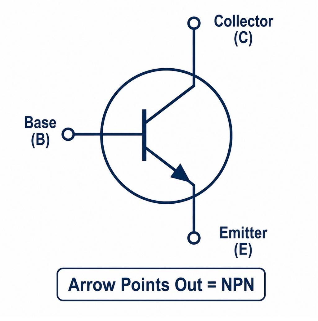
Figure: NPN transistor symbol showing collector, base, and emitter with arrow pointing away from the base.
The arrow on the emitter points outward, away from the base. This is the fastest way to identify an NPN transistor on a schematic.
What Is a PNP Transistor?
PNP Transistor Structure
A PNP transistor has a thin N-type layer sandwiched between two P-type layers. Holes are the majority carrier.
How a PNP Transistor Works
- The base must sit roughly 0.7V below the emitter to turn the transistor on.
- Once on, current flows from emitter to collector.
- A small base current (flowing out of the base) controls the larger emitter-collector current.
PNP Transistor Symbol
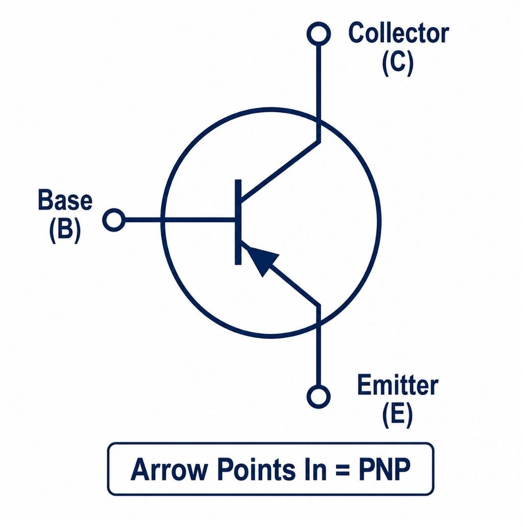
Figure: PNP transistor symbol showing collector, base, and emitter with arrow pointing toward the base.
The arrow points inward, toward the base, the mirror image of the NPN symbol.
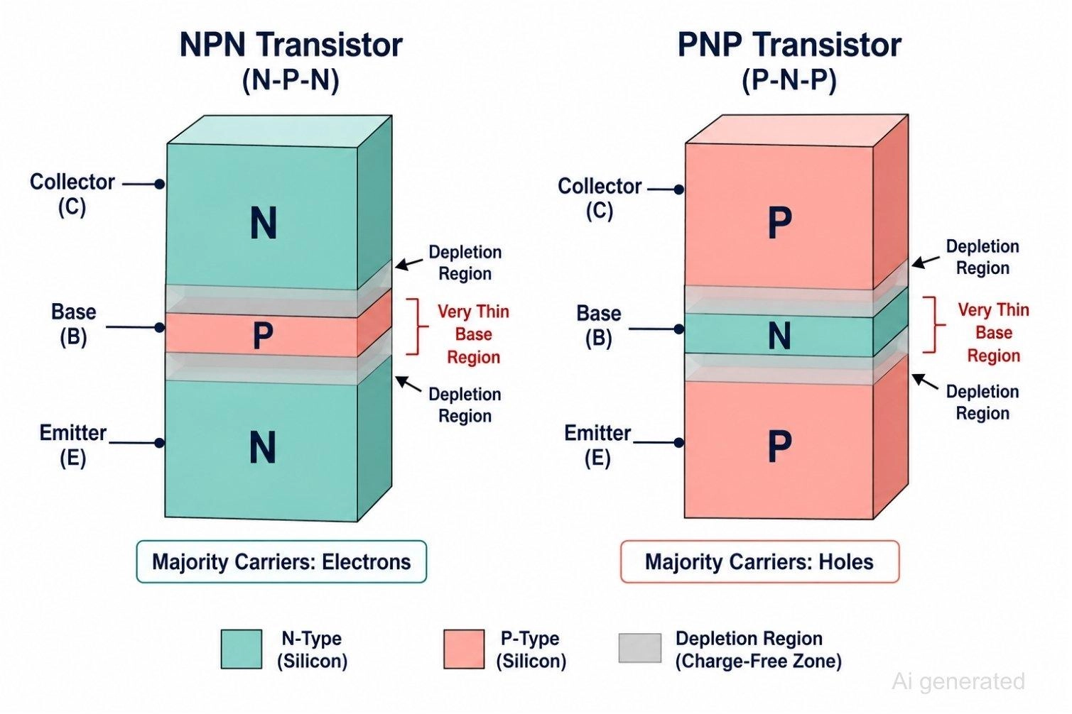
Figure: Comparing internal semiconductor layer structure of NPN and PNP transistors.
How to Identify NPN and PNP Transistor
The Arrow Rule:
- NPN = arrow Not Pointing iN (arrow points out)
- PNP = arrow Pointing iN (arrow points in)
This is the fastest way to read a transistor symbol on any schematic without checking a datasheet.
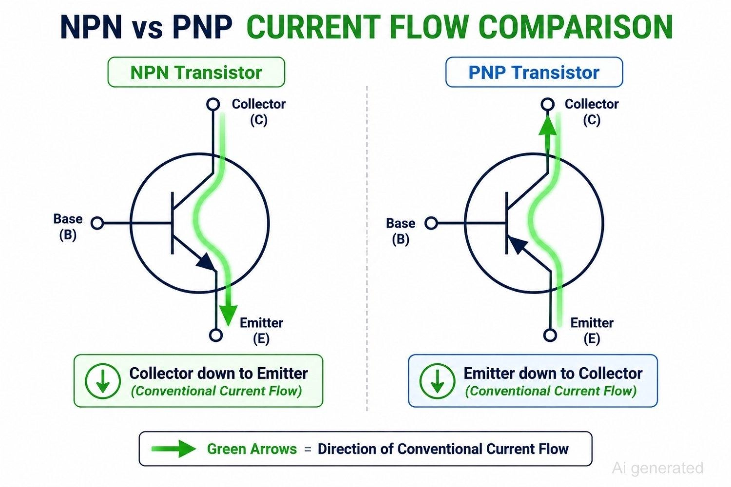
Figure: Comparing current flow direction in NPN and PNP transistors
Current flow direction follows the same rule as the arrow: NPN conducts from collector to emitter, PNP conducts from emitter to collector.
NPN vs PNP Transistor: Why Are NPN Transistors More Common?
Higher Electron Mobility
Electrons move faster through silicon than holes. This single carrier-mobility difference underlies most of the practical gap between NPN and PNP behavior.
Faster Switching Speed
The mobility advantage translates into shorter rise and fall times, which is why NPN parts dominate in:
- Digital logic interfacing
- Embedded systems
- Microcontroller output stages
Easier Ground-Referenced Design
Most PCB designs reference a common ground rail. An NPN transistor switching a load to ground fits naturally into this layout, which is part of why low-side switching with NPN has become the default approach in general-purpose circuits, especially when weighing the trade-offs of choosing surface mount vs through hole configurations for active devices.
Low-Side vs High-Side Switching with NPN and PNP Transistors
NPN Transistor Low-Side Switching
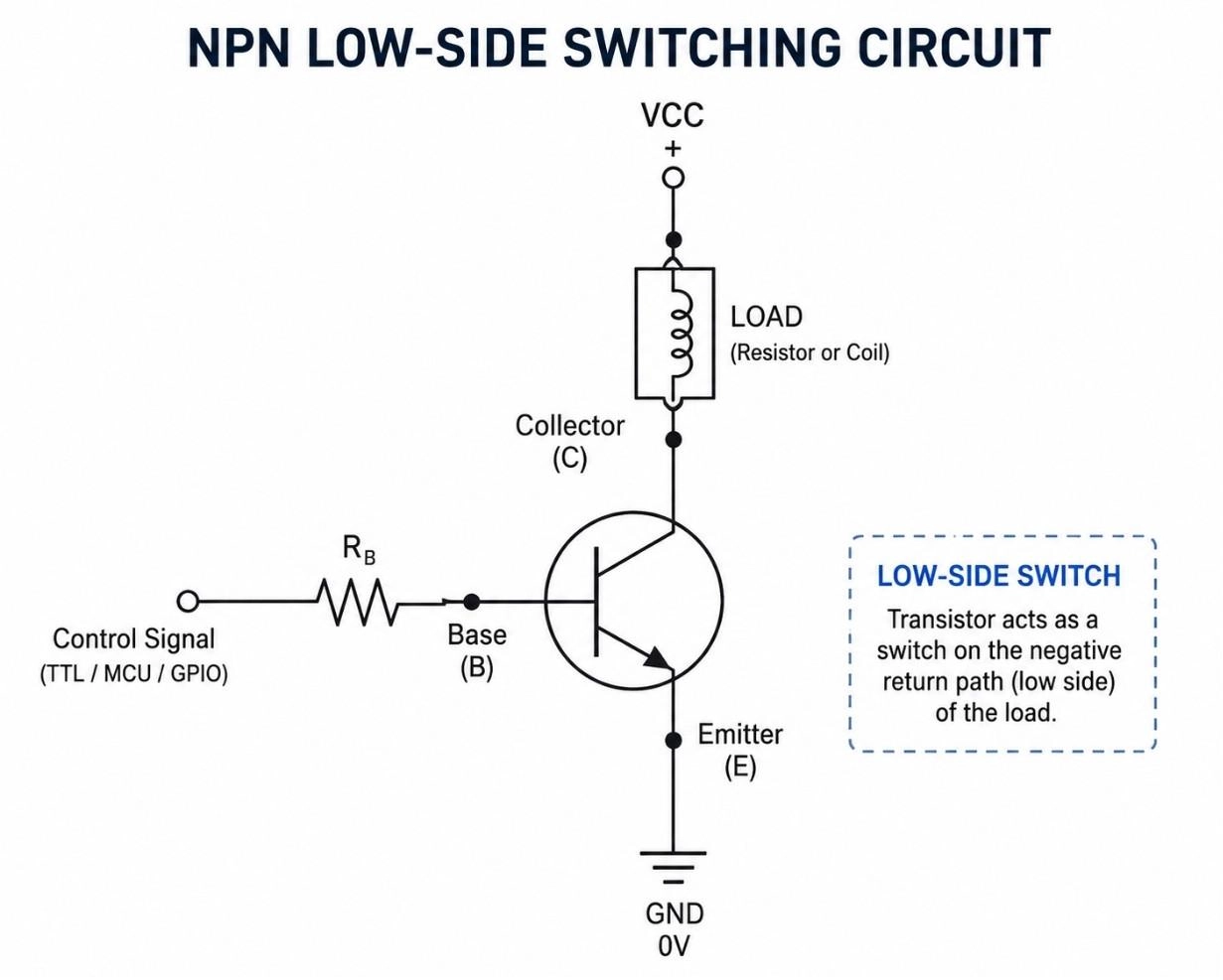
Figure: Schematic of an NPN transistor switching a load on the low side, with the load connected to VCC and the transistor switching to ground.
The load sits between the supply rail and the collector. The transistor's emitter ties to ground, so the transistor switches the return path.
PNP Transistor High-Side Switching
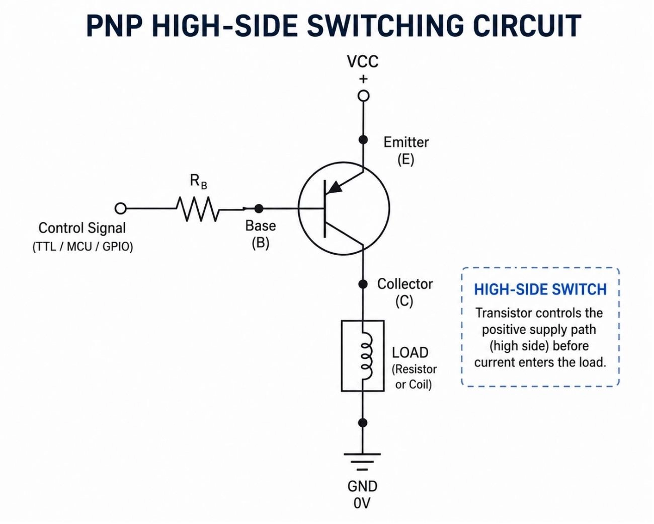
Figure: Schematic of PNP transistor switching a load on the high side, with the transistor connected to VCC and the load connected to ground."
The transistor sits between the supply rail and the load. The PNP switches the supply side, which is the only practical option when the load's other terminal is fixed to ground.
When to Use Each Configuration
| Application | Recommended |
|---|---|
| MCU-controlled relay | NPN |
| LED driver | NPN |
| Power rail switching | PNP |
| Battery-powered load control | PNP |
NPN vs PNP Transistor: Current Sinking and Current Sourcing
This distinction matters most in industrial automation and PLC wiring, where sensor outputs and PLC inputs must match polarity.
Current Sinking (NPN Transistor)
In a sinking configuration, the transistor pulls the signal line down to 0V when active. Current flows into the device.
Current Sourcing (PNP Transistor)
In a sourcing configuration, the transistor pushes positive voltage onto the signal line when active. Current flows out of the device to the load.
Why PLC Inputs Often Specify NPN or PNP Sensors
A PLC input module is wired internally for one polarity only, either a pull-up (for NPN/sinking sensors) or a pull-down (for PNP/sourcing sensors). Connecting the wrong sensor type to a mismatched input will not register correctly and, on some hardware, can create a wiring fault. Always confirm the sensor output type against the PLC input module specification before wiring.
Common Applications of NPN and PNP Transistors
NPN Transistor Applications
- LED switching
- Relay driving
- Logic-level switching circuits
- Microcontroller GPIO interfacing
NPN Transistors in Microcontroller Projects
NPN transistors are the default choice for driving relays, motors, and high-current LEDs from Arduino, ESP32, and STM32 boards. A logic-high GPIO output can drive the base directly through a current-limiting resistor, switching the load to ground on the low side. This is why most beginner-level transistor switch circuit tutorials use NPN as the npn transistor example.
When selecting surface-mount packaging for compact board builds, knowing how to decipher SMD transistor codes is an essential layout skill.
PNP Transistor Applications
- High-side power switches
- Power management and load-disconnect circuits
- Complementary amplifier stages
A common PNP transistor example is a high-side load switch that disconnects a battery-powered circuit to cut standby current.
NPN and PNP transistors: Complementary Push-Pull Design
NPN and PNP transistors are frequently paired in push-pull output stages, where each device handles one half of an AC or bidirectional signal cycle. This complementary arrangement is common in audio amplifier outputs and motor driver stages.
Popular Examples of NPN and PNP Transistors
| NPN Transistor | PNP Equivalent |
|---|---|
| 2N3904 | 2N3906 |
| BC547 | BC557 |
| 2N2222 | 2N2907 |
| S8050 | S8550 |
These complementary pairs share similar voltage and current ratings but opposite polarity, making them useful as drop-in replacements when a design needs the opposite switching direction.
Check the JLCPCB Parts Library to verify component availability and simplify sourcing. With JLCPCB's PCB Assembly service, common small-signal BJTs can be sourced and assembled automatically, helping you move from design to production faster.
NPN vs PNP Transistor: How to Choose
| Requirement | Recommended Choice |
|---|---|
| Fast switching | NPN |
| MCU control | NPN |
| Ground-referenced switching | NPN |
| High-side load control | PNP |
| Complementary amplifier stage | Both |
FAQs about NPN and PNP Transistors
Q: Can I replace a PNP transistor with an NPN transistor?
No. They require opposite base-bias polarities (positive base-to-emitter voltage for NPN; negative for PNP) and opposite current directions. Replacing one with the other requires redesigning the biasing network.
Q: Why is an NPN transistor faster?
Its majority charge carriers are electrons, which have roughly two to three times higher mobility in silicon than the holes used as majority carriers in PNP transistors, resulting in quicker state transitions.
Q: What do the arrows on transistor symbols mean?
The arrow is on the emitter terminal and shows conventional current flow when conducting: pointing outward (away from the base) for NPN, and inward (toward the base) for PNP.
Q: Which transistor is better for Arduino projects?
NPN transistors. They are easier to drive directly from a microcontroller's logic-high output (5V or 3.3V) through a simple resistor to switch loads on the ground-referenced low side.
Q: Can NPN and PNP transistors be used together?
Yes. They are commonly paired in push-pull output configurations (such as in amplifiers and motor drivers), where the NPN handles the positive half-cycle and the PNP handles the negative half-cycle.
Q: Why are PNP transistors less common?
Their lower carrier mobility makes them slower than NPNs. Additionally, common system designs default to low-side switching, where ground-referenced NPN configurations are simpler and more efficient to control.
Q: What is the voltage drop across a transistor?
A forward-biased base-emitter junction drops roughly 0.7V. When fully saturated as a switch, the collector-emitter saturation voltage (Vce(sat)) drops to a very low 0.1V to 0.3V depending on the load.
Q: Is a MOSFET better than a transistor?
Neither is universally better. MOSFETs are voltage-controlled devices with lower power losses at high currents (ideal for power circuits), whereas BJTs are current-controlled, cheaper, and simpler for low-current signals.
Q: What happens if the base resistor is omitted?
The forward-biased base-emitter junction will act like an open diode, drawing unrestricted current. This will likely burn out the driving GPIO control pin, destroy the transistor, or both.
Q: Are MOSFETs replacing BJTs?
Yes, in high-current power stages, processor cores, and modern power supply designs. However, BJTs remain irreplaceable for low-current signal switching, specialized analog/RF circuits, and highly cost-sensitive systems.
Conclusion
NPN and PNP transistors perform similar switching and amplification roles but differ in carrier type, current direction, and base bias polarity.
For most microcontroller and embedded designs, an NPN transistor is the simplest choice. When a load must be switched on the positive supply rail, a PNP transistor becomes the better solution.
Understanding the difference between low-side and high-side switching is often the deciding factor when selecting between the two.
Popular Articles
• SMD Diode Code Lookup: Full List, Marking Guide & Identification [2026 Guide]
• SMD Resistor Package Sizes: Complete Size Chart, Footprints & How to Choose
• SMD Capacitor Codes: Identification, Markings, and Polarity
• SMD Capacitor Sizes: Complete Size Chart and Selection Tips for PCB Design and Assembly
• How to Solder SMD Components Like a Pro [2026 Updated]
Keep Learning
PoP Package (Package on Package) Explained: Architecture, Assembly, and SMT Challenges
In the race for miniaturization, fitting more processing power into smaller footprints is the ultimate challenge for PCB designers. Package on Package (PoP) technology answers this by integrating logic and memory vertically, becoming the standard for modern mobile processors. However, this 3D architecture demands advanced SMT assembly capabilities beyond standard fabrication. JLCPCB specializes in the high-precision manufacturing required to master these complex stacks. This guide covers how PoP packa......
What Is a PQFP Package? Plastic Quad Flat Package Design, Footprint, and Assembly Guide
The Plastic Quad Flat Package (PQFP) is a widely used IC package in industrial, automotive, and embedded designs. This article provides a practical, engineering-focused guide to PQFP package. It explains how PQFP is built, when it makes sense to use it, how it compares with newer package types, and what designers should consider in terms of footprint design, thermal performance, signal integrity, manufacturing, and reliability. What Is a PQFP Package (Plastic Quad Flat Package)? A Plastic Quad Flat Pa......
Small Outline Integrated Circuit (SOIC): Package, Specs & Uses
As designs transition from legacy through-hole components to high-density Surface Mount Technology (SMT), the Small Outline Integrated Circuit (SOIC) remains the industry standard for operational amplifiers, flash memory, sensors, and microcontrollers. It stands as a testament to balanced engineering, offering a perfect compromise between the miniaturisation demanded by modern consumer electronics and the ruggedness required for industrial applications. This article serves as a definitive engineering ......
A Complete Guide to Surface Mount Device (SMD)
Imagine holding a smartphone in your hand. Inside that sleek device lies a complex network of thousands of miniature components — resistors smaller than a grain of rice, capacitors thinner than a fingernail, and integrated circuits containing millions of transistors. Without Surface Mount Technology (SMT) and its compact Surface Mount Devices (SMDs), none of this would exist. Just a few decades ago, electronics were bulky. Radios filled desks, computers filled rooms, and assembling a circuit meant dri......
Circuit Breaker Types Explained: MCB, MCCB, RCCB, RCBO, ACB, VCB & SF6 Circuit Breakers
A circuit breaker automatically disconnects power when it detects faults such as overloads or short circuits, protecting equipment and reducing fire risk. Different circuit breaker types are designed for different voltage levels, current ratings, and applications, from household distribution boards to high-voltage substations. This guide explains the most common types - including MCBs, MCCBs, RCCBs, RCBOs, ACBs, VCBs, and SF6 breakers and helps you choose the right one for your application. Figure: Ci......
Quad Flat Package (QFP): The Engineer's Guide to Design, Assembly and Thermal Management
What is QFP Package? The Quad Flat Package (QFP) is one of the most popular surface mount technology (SMT) package formats throughout the history of electronic manufacturing. After it became standard in the 1980s, the QFP has been the industry standard for integrated circuits (ICs) with moderate to high pin counts that typically range from 32 to 304 pins, so it was a good alternative for simple SOIC packages and complex Ball Grid Arrays (BGAs) at the same time. Defined by its "gull-wing" leads extendi......