
SMD LED Explained: Types, Packages, Applications, and How to Choose
17 min
- What Is an SMD LED?
- SMD LED vs Traditional LED (DIP): Key Differences
- Common SMD LED Package Explained
- How to Choose the Right SMD LED for Your PCB
- SMD LED vs COB LED — Which One Should You Use?
- SMD LED Types by Structure
- SMD LED Assembly & Polarity Tips
- SMD LED Manufacturing and Assembly with JLCPCB
- Conclusion
- Frequently Asked Questions (FAQ)
SMD LED has become the standard light source in modern electronics and lighting products. From LED strips and displays to automotive dashboards and consumer devices, SMD LEDs are everywhere—but many designers and buyers still struggle to choose the right type.
Package sizes, brightness, heat dissipation, color control, and assembly constraints all affect performance and reliability. Choosing the wrong SMD LED can lead to overheating, uneven lighting, or manufacturing issues.
This guide breaks down what an SMD LED is, how it differs from traditional LEDs, and how to select the right package for your application—clearly, practically, and without unnecessary technical jargon.
What Is an SMD LED?
An SMD LED (Surface Mount Device LED) is a light-emitting diode designed to be mounted directly on the surface of a printed circuit board (PCB) rather than inserted through holes like traditional LEDs. “Surface-mounted” means the LED sits flat on the PCB pads, allowing better heat dissipation, smaller size, and higher brightness.
Modern electronics rely on SMD LEDs because they are compatible with automated SMT assembly, save valuable board space, and provide more efficient and reliable lighting. From LED strips and displays to automotive dashboards, SMD LEDs have become the default choice for most PCB-based lighting applications.
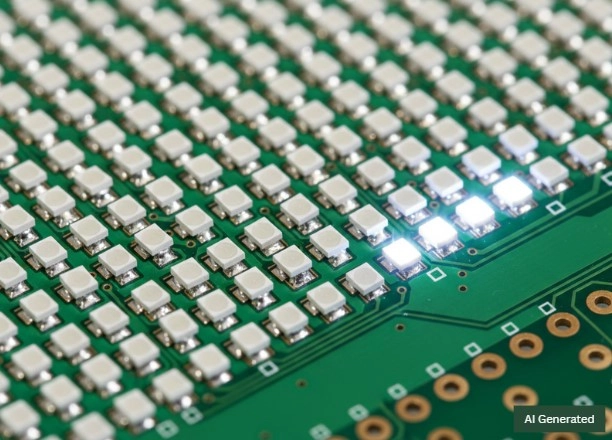
SMD LED
SMD LED vs Traditional LED (DIP): Key Differences
While both technologies rely on the same semiconductor physics—converting current to photons via electroluminescence at a P-N junction, their design and mounting create significant differences in performance, efficiency, and application.
1. Mounting and Architecture
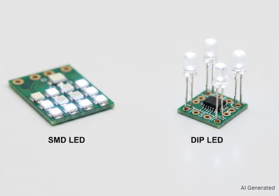
DIP LED: Through-hole mounting with long metal leads. Leads can restrict heat flow and occupy more PCB space.
SMD LED: Mounted directly on the PCB surface without leads. This compact design improves heat dissipation and allows up to 80% board space savings, making SMD LEDs ideal for high-density applications.
2. Light Output and Beam Angle
The most significant difference in performance lies in Luminous Density:
DIP LED: DIP (Dual In-Line Package) LEDs generally consist of high-power chips with very narrow beam angles (ranging from 25 degrees to 40 degrees), thus they are considered to be excellent for long-distance signaling applications, but they create really harsh "hot spots" though.
SMD LED: SMDs make use of a grid of tiny LED chips with broad, wisely placed beam angles (maximum 120 degrees). Since they can be packed close together, their separate light outputs blend into a stronger, more even lighting with less darkness.
3. Thermal Efficiency and Longevity
DIP LED: Concentrated heat on a single chip can reduce lifespan.
SMD LED: An SMD cluster in which every chip can do less power work, hence, less concentrated heat is produced when compared to a single high-power DIP diode. This even spread of heat, along with surface mounting's effective heat dissipation, SMDs' power consumption is lower, and their lifespan is really long.
4. Typical Applications
Opt for Traditional DIP LEDs for high-vibration outdoor signage or simple status indicators where a focused beam is more valuable than uniform coverage.
Opt for SMD LEDs for high-density strips, displays, and architectural lighting. While SMDs are undeniably brighter and last longer, the brightness can sometimes be too much; for soft "mood" lighting required in indoor spaces, engineers might choose regular LEDs with bigger spaces to prevent over-lighting.
| Feature | DIP LED | SMD LED |
|---|---|---|
| Mounting | Through-hole | Surface-mounted |
| Beam Angle | 25°–40° | Up to 120° |
| Heat Dissipation | Concentrated | Spread across the PCB |
| Power Efficiency | Lower | Higher |
| Ideal Use | Outdoor signage, indicators | High-density strips, displays, and architectural lighting |
Choosing the right LED depends on brightness, thermal limits, and application requirements. Next, we’ll break down common SMD LED packages like 0603, 2835, and 5050 for practical selection guidance.
Common SMD LED Package Explained
SMD LED package codes (such as 0603 or 5050) indicate the physical size of the LED in millimeters, but they also hint at brightness, power handling, and thermal performance.
Note: Actual power consumption, luminous flux, and efficiency may vary depending on LED manufacturer, binning, drive current, and thermal design.
| Package Code | Dimensions (mm) | Power (W) | Luminous Flux (lm) | Efficiency (lm/W) | Primary Use Case |
|---|---|---|---|---|---|
| 0603 | 1.6 x 0.8 | 0.02 – 0.05 | 2 - 5 | ~ 20 | High-density status indicators |
| 0805 | 2.0 x 1.25 | 0.06 – 0.1 | 3 - 7 | ~ 30 | UI & button backlighting |
| 1010 | 1.0 x 1.0 | 0.05 – 0.1 | 1 – 3 | ~ 40 | High-res video walls (Mini-LED) |
| 3528 | 3.5 x 2.8 | 0.07 - 0.08 | 4 - 8 | 70 - 100 | Decorative accent lighting |
| 2110 | 2.1 x 1.0 | 0.1 - 0.2 | 8 - 15 | 90 - 140 | "Dotless" linear LED strips |
| 2216 | 2.2 x 1.6 | 0.1 - 0.2 | 8 - 18 | 90 - 150 | Ultra-slim cabinet lighting |
| 3024 | 3.0 x 2.4 | 0.1 – 0.2 | 10 - 12 | 80 - 100 | Rugged industrial/auto signals |
| 2835 | 2.8 x 3.5 | 0.2 - 0.5 | 20 - 60 | 70 - 125 | Commercial office illumination |
| 5050 | 5.0 x 5.0 | 0.2 – 0.6* | 18 – 60* | 60 – 100 | High-power RGB/Multi-die |
SMD LED 5050 Note: A white single-die 5050 typically operates at 0.2–0.3 W. RGB 5050 LEDs integrate three dies (R/G/B), with total power consumption of up to 0.6 W, but lower luminous efficacy than white versions.
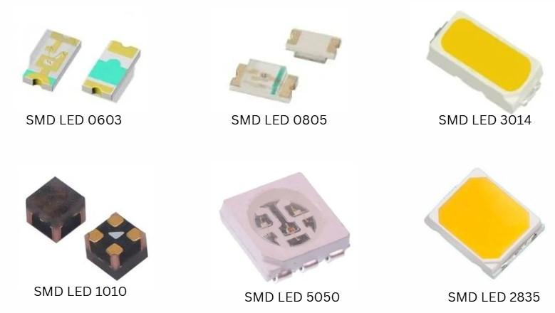
Common SMD LED package
SMD LED 0603
The 0603 (1.6 x 0.8 mm) is the standard for high-density status indicators and is available in colors of red, green, blue, white, etc. Its ultra-compact footprint is ideal for wearables and compact consumer electronics where space is the primary constraint and high-intensity brightness is not required.
SMD LED 0805
The 0805 comes in at 2.0 x 1.25 mm. It has more surface area than the 0603, so better light flux. Handling is easier, too, for machines that pick and place them automatically. That is why it ends up in automotive dashboards or backlighting buttons.
SMD LED 1010
The 1010 (1.0 x 1.0 mm) is commonly used in Mini-LED backlight and display applications.
The square and sub-miniature shape lets pixels get super tight, so displays look seamless, and diodes are invisible to the naked eye.
SMD LED 3528
The SMD LED 3528 (3.5 × 2.8 mm) is one of the earliest and most widely used mid-size SMD LED packages. It typically operates at low current and moderate brightness, making it a cost-effective solution for basic illumination.
Because of its stable performance and long service life, the 3528 is commonly used in decorative LED strips, signage backlighting, and accent lighting, where efficiency and reliability matter more than high luminous output.
SMD LED 2110
The SMD LED 2110 (2.1 × 1.0 mm) is a newer, ultra-narrow package developed specifically for high-density linear lighting. Its slim width allows LEDs to be placed extremely close together, enabling “dotless” lighting effects without visible hotspots.
Thanks to its compact size and decent efficiency, the 2110 package is widely used in modern LED light strips, architectural contours, and commercial linear fixtures where uniform light distribution is critical.
SMD LED 2216
The SMD LED 2216 (2.2 × 1.6 mm) is designed for ultra-thin lighting applications that demand both high efficiency and minimal profile height. Compared with older packages, it delivers higher luminous efficacy with improved thermal performance.
This makes the 2216 a popular choice for cabinet lighting, furniture lighting, and premium architectural designs, especially where space is limited but consistent brightness is required.
SMD LED 3024
The 3024 (3.0 x 2.4 mm) is suitable for heavy-duty industrial and automotive lighting. It offers a perfect combination of light output and the ability to withstand higher temperatures, thus capable of being used in high-vibration / harsh environments such as vehicle turn signals.
SMD LED 2835
The SMD LED 2835 (2.8 × 3.5 mm) is a high-efficiency mid-power LED package optimized for general illumination. Its larger heat dissipation area allows it to operate at higher power levels while maintaining good thermal stability.
As a result, the 2835 is widely used in office lighting panels, residential LED bulbs, and commercial luminaires, offering a strong balance between brightness, efficiency, and lifespan.
SMD LED 5050
The SMD LED 5050 (5.0 × 5.0 mm) is a high-power, multi-die LED package that typically integrates three LED chips in a single housing. This design enables high brightness and excellent RGB color mixing.
Because of its versatility and output capability, the 5050 package is commonly used in RGB LED strips, smart lighting systems, stage lighting, and architectural wash lighting, where strong illumination and color control are essential.
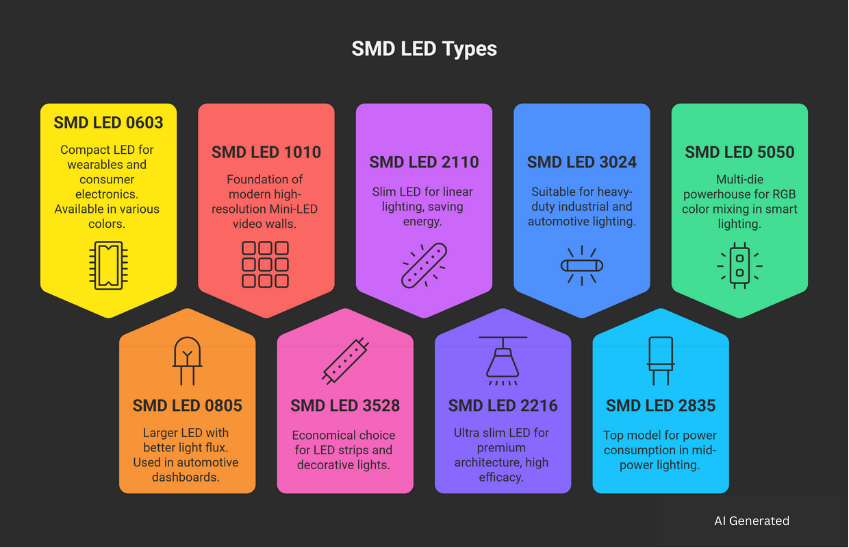
SMD LED Types
How to Choose the Right SMD LED for Your PCB
Choosing the right SMD LED depends on a few practical design constraints rather than chasing maximum brightness.
First, consider available PCB space and assembly method. Smaller packages like 0603 or 0805 are ideal for indicators and dense layouts, while larger packages such as 2835 or 5050 suit illumination-focused designs.
Second, match the light output to the application. For uniform lighting and linear strips, slim packages like 2110 or 2216 help avoid visible dots. For general lighting, mid-power packages such as 2835 offer the best balance of brightness and efficiency.
Finally, evaluate thermal performance and power handling. Higher-power LEDs require sufficient copper area and thermal paths on the PCB to ensure reliability and long lifespan.
In short, the best SMD LED is the one that fits your space, brightness, and thermal design constraints—not simply the largest or brightest option.
SMD LED vs COB LED — Which One Should You Use?
Engineers often choose between SMD LEDs and COB LEDs depending on brightness, uniformity, and control requirements.

SMD LED vs COB LED
The main advantage of SMD LEDs is that they are made up of separate, pre-packaged diodes that are mounted on a PCB, providing versatility and individual control.
In contrast, COB LEDs utilize multiple bare dies directly integrated onto a single substrate to produce a high-intensity "light panel" with excellent thermal dissipation.
| Feature | SMD LED | COB LED |
|---|---|---|
| Design | Discrete components soldered to the PCB | Multiple bare dies on a single substrate |
| Size | Smaller | Larger |
| No. of Diodes | Contains a few diodes (usually 1-3) | Contains a higher no. of diodes on a single chip |
| Heat Management | Dispersed across the PCB copper | Superior via direct substrate contact |
| Light Quality | Visible "dots" of light | Seamless, uniform "light panel." |
| Versatility | High (supports RGB mixing) | Lower (usually single-color) |
| Brightness | Bright (Scalable, depending on package count and drive current) | Very bright (single light) |
| Efficiency | High, but depends on the configuration | High efficiency at higher power levels due to superior thermal management. |
| Cost | Typically lower | Higher |
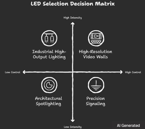
LED selection decision
Choose SMD LEDs (Surface Mount Device) When:
SMDs are the professional choice for projects requiring high versatility, modularity, or individual pixel control.
● Intelligent & RGB Systems: Each SMD can be powered through separate circuits, hence they are the only practical alternative for Addressable LED strips (for instance, WS2812B), where each diode can be independently controlled, dynamic signage, and "Tunable White" systems where the CCT must shift continuously throughout the operation.
● Precision Signaling: SMDs such as the 0603 or 0805 are preferred for PCB status indicators, consumer electronics user interfaces, and automotive dashboard backlighting due to their small z-height and standard footprints.
● High-Resolution Video Walls: The non-visible feature of SMDs supports pixel pitches (down to 0.9 mm). Such a resolution with sharpness and detail is a must not only for indoor studio screens but also for control room displays.
Choose COB LEDs (Chip-on-Board) When:
COB modules are the engineering standard for high-intensity, uniform, and thermally demanding applications.
● Industrial High-Output Lighting: In places like warehouses or factories, a single source of light would still need to produce a massive lumen output for High-Bay fixtures. The highest luminous flux per square inch is delivered by COBs, which also have proficient thermal dissipation.
● Professional Photography & Optics: COBs produce a "single point source" effect and simulate natural sunlight. They are very useful for the main lights in studios and high-quality filmmaking due to their shadow-free, reduced-glare beams with high CRI (Color Rendering Index).
● Architectural Spotlighting: COBs eliminate the "polka-dot" reflections seen in multi-die SMD fixtures. Instead, they generate a smooth, museum-quality wash that brings out the textures but does not create harsh visual artifacts or overlapping shadows.
| Design Goal | Best Choice | Technical Justification |
|---|---|---|
| Color Changing / RGB | SMD | Supports multi-channel circuitry and PWM control. |
| Maximum Power Density | COB | Direct substrate bonding handles higher thermal loads. |
| "Dotless" Linear Light | High-density SMD or COB | High LED density or continuous LES |
| Ease of Maintenance | SMD | Discrete components allow for individual diode replacement. |
| Shadow-Free Output | COB | Unified Light-Emitting Surface (LES) provides homogeneous beams. |
SMD LED Types by Structure
In SMT assembly, the orientation of the LED die relative to the solder pads determines its application in direct-lit vs. edge-lit systems.
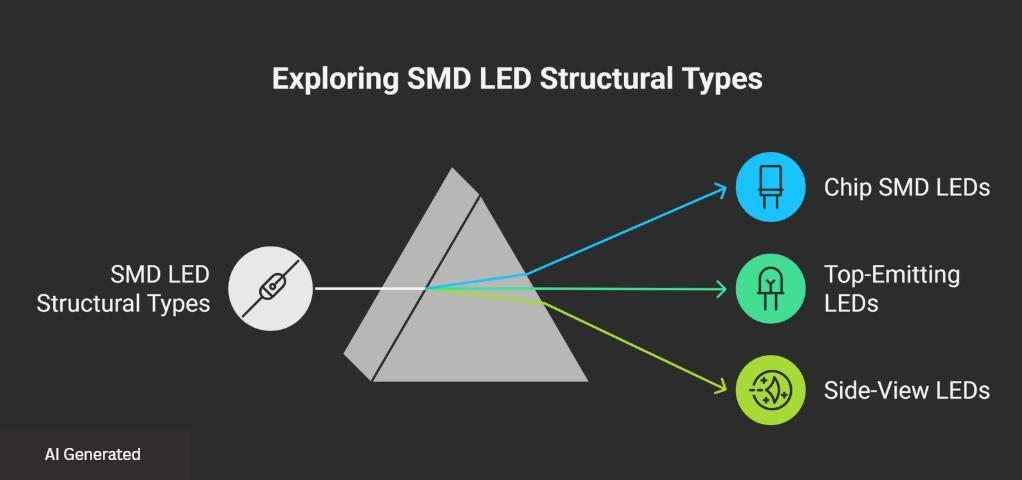
SMD LED Types by Structure
1. Chip SMD LEDs (Flat-Mount Geometry)
These are the standard "leadless" packages where the semiconductor die sits directly on a ceramic or high-temp plastic substrate.
● Engineering Edge: These packages offer the lowest Thermal Resistance Junction-to-Solder point. Because the heat path is vertical and direct, they are the most efficient for thermal management.
● Assembly Dynamics: Their flat, symmetrical profile allows for maximum nozzle suction stability during high-speed pick-and-place (>50k CPH), minimizing "tombstoning" or rotation errors during the reflow phase.
● Typical Use: General-purpose signaling, high-power floodlights, and status indicators where PCB real estate is the only constraint.
2. Top-Emitting LEDs (Vertical Optical Axis)
This is the most common configuration, where the optical axis is perpendicular to the PCB plane.
● Optical Profile: The distribution is normally a Lambertian one (120 degrees). The light goes out "upward" away from the board.
● Design Consideration: The engineers have to consider the Encapsulant Index of Refraction. Most top-emitters make use of a silicone or epoxy dome lens. The dome lens helps protect the LED chip and improves light extraction.
● Typical Use: Backlighting for buttons, ceiling panels, and any application where the observer is facing the PCB surface.
3. Side-View LEDs (Parallel Optical Axis)
Also known as "Right-Angle" LEDs, these are engineered so the light-emitting surface is perpendicular to the solder pads.
● Optical Coupling: The light is emitted parallel to the PCB. This is mathematically essential for Total Internal Reflection (TIR) in edge-lit light guide plates (LGP).
● Mechanical Constraints: These packages sometimes incorporate reinforcing pins or side-pads for enhanced mechanical "peel strength." In their absence, the torque of the external lens or housing might easily cause the LED to detach from the board.
● Z-Height Engineering: Essential for ultra-slim devices (smartphones, tablets, and backlit keyboards). If the LED is positioned on the edge and its light "sideways" into a diffuser, the total display thickness can be made less than 2mm.
SMD LED Assembly & Polarity Tips
Proper assembly and correct polarity are critical to the reliability of any SMD LED design.
1. Polarity identification: SMD LEDs are polarized devices. The cathode is usually marked by a notch, chamfered corner, green mark, or polarity symbol on the package. Always verify the manufacturer’s datasheet before PCB layout and placement.
2. PCB footprint & orientation: Ensure the PCB footprint matches the LED package exactly. Incorrect pad size or orientation can cause misalignment during reflow or uneven solder joints.
3. SMT assembly considerations: SMD LEDs are fully compatible with automated pick-and-place and reflow soldering. Use standard reflow profiles and avoid excessive peak temperatures to prevent lumen degradation or color shift.
4. Rework & handling: If rework is needed, use a hot-air station with controlled airflow. Avoid overheating nearby LEDs, as repeated thermal stress can shorten lifespan.
Correct polarity and controlled thermal processing are key to achieving consistent brightness and long-term SMD LED reliability.
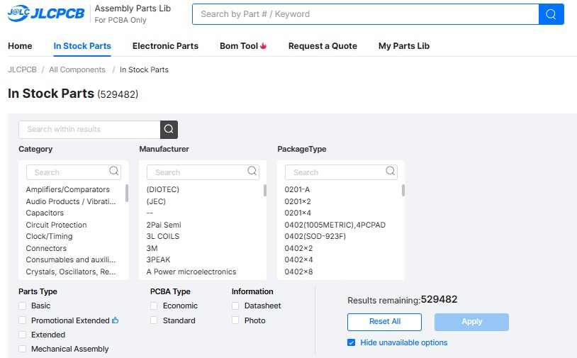
SMD LED Manufacturing and Assembly with JLCPCB
JLCPCB streamlines the transition from SMD LED design to volume assembly by combining a large-scale component supply chain with advanced SMT production lines.
Through the JLCPCB Parts Library, engineers can access over 620,000 traceable components, including widely used LED brands such as Xinglight. The platform allows filtering by package type, forward voltage range, and optical specifications defined in the datasheet. As a result, whether a design requires a compact 0603 indicator or a high-power 5050 RGB module, consistent electrical and optical performance can be maintained within each production run.
In addition to component sourcing, JLCPCB’s automated PCBA services utilize high-speed pick-and-place equipment and controlled reflow soldering profiles, ensuring accurate placement of every SMD LED. Automation significantly reduces common risks associated with manual assembly, such as polarity errors or thermal stress to sensitive semiconductor junctions.
To further ensure reliability, all assembled boards undergo Automated Optical Inspection (AOI) to verify solder quality and component positioning. From early-stage SMD LED prototypes to large-scale production, JLCPCB provides a cost-effective, traceable, and efficient manufacturing path for bringing LED designs to market.

Conclusion
Choosing the right SMD LED is a practical engineering trade-off between light output, thermal limits, and assembly constraints. While SMD LEDs offer clear advantages in efficiency and compact size, overall system performance ultimately depends on selecting the appropriate package and ensuring reliable manufacturing execution.
By working with experienced manufacturing partners such as JLCPCB, engineers can translate complex LED designs into stable, repeatable, and scalable production, from prototype builds to volume assembly.
Frequently Asked Questions (FAQ)
Q1. What is a DIP LED?
A DIP (Dual In-line Package) LED is the traditional "bulb" style LED with two long wire legs. In contrast to SMD LEDs that are fixed on the surface of a board, DIP LEDs are plugged into the PCB. Today, they are largely applied in massive outdoor scoreboards or uncomplicated DIY electronics because of their robustness and soldering.
Q2. Why do SMD LEDs have a small "notch" or green mark on one corner?
That mark is a physical "polarity indicator." LEDs only work if the current goes in the right direction, one direction only. So the notch points to the cathode side, the negative one. Machines in assembly use it to get the orientation right, and engineers do too. If you put it in backwards, nothing lights up, and it might get damaged pretty quickly.
Q3. Can I replace a single broken LED in an SMD array?
Yes, but it requires professional tools. But not like with the regular ones, where you just clip them off easily. These are glued down with solder to the board. Usually, people use a hot air rework station for that, to heat the solder without messing up the plastic on nearby LEDs. It takes some real tools, not just basic stuff.
Q4. Does the color of the SMD LED change its price?
That is a broad yes. Colors like Red and Yellow, which are the standard ones, are generally the least expensive ones. The Blue, White, and True Green LEDs, through the use of a different chemical compound (Indium Gallium Nitride), which is more complex to manufacture, often make them a bit pricier than basic red indicators.
Q5. What happens if I use an SMD LED without a resistor?
The LED will probably "flash-fry." LEDs are current-thirsty devices; without a resistor that acts as a "speed limit," the LED will suck in too much power, heat instantly, and thus, burn out. Even the tiniest 0603 LED needs a resistor to be and remain bright.
Popular Articles
• SMD Capacitor Sizes: Complete Size Chart and Selection Tips for PCB Design and Assembly
• SMD Diode Code Lookup: Full List, Marking Guide & Identification [2026 Guide]
• SMD Resistor Package Sizes: Complete Size Chart, Footprints & How to Choose
• SMD Capacitor Codes: Identification, Markings, and Polarity
• How to Solder SMD Components Like a Pro [2026 Updated]
Keep Learning
What Is the ESP32? A Complete Guide to Features, Architecture, Modules, Programming, and Applications
From Wi-Fi-enabled temperature sensors and wearable health monitors to industrial gateways and AI-powered cameras, the ESP32 microcontroller has become one of the world's most widely adopted wireless embedded platforms. Combining a powerful processor with integrated Wi-Fi and Bluetooth, it lets engineers build connected devices without separate networking hardware. This guide covers ESP32 specifications, architecture, the full family of variants, development boards, programming tools, and real-world E......
How to Choose the Right STM32 Microcontroller: Compare Series, Cortex-M Cores, and Key Features
STMicroelectronics ships thousands of STM32 MCU part numbers across more than a dozen series, and that variety is exactly what makes STM32 microcontroller selection difficult. Pick the wrong family, and you pay for it later: oversized BOM cost, wasted power budget, or a board respin when a peripheral turns out to be missing. This STM32 microcontroller selection guide breaks the decision into a five-step framework built on practical engineering criteria, not datasheet marketing copy, so you can match a......
SMD Transistor Code Lookup: Identify Markings, Pinout & Multimeter Test Guide
Repairing a circuit board often brings a familiar frustration: staring at a tiny, three-legged black component with an obscure two- or three-letter code. Whether troubleshooting a bare prototype or a mass-produced PCBA, knowing how to quickly decode these surface-mount device (SMD) markings is an essential skill for any electronics engineer or repair technician. In this comprehensive guide, you will learn: 1. How to decode SMD transistor marking codes 2. How to identify BJT vs MOSFET types 3. How to f......
SMD Capacitor Sizes: Complete Size Chart and Selection Tips for PCB Design and Assembly
In the world of modern electronics, surface mount devices (SMDs) have revolutionized board design, allowing for smaller, faster, and more efficient printed circuit boards. When designing a PCB, selecting the correct SMD capacitor sizes is one of the most critical decisions an engineer must make to ensure both electrical reliability and manufacturability. In this article, you will find practical, authoritative guidance on: Comprehensive SMD capacitor size charts for quick reference. How to read imperia......
SMD Diode Code Lookup: Full List, Marking Guide & Identification [2026 Guide]
In modern electronics, surface-mount diodes are used everywhere - from power input protection circuits to high-speed signal routing. Because these components are extremely small, manufacturers cannot print full part numbers on their bodies. Instead, they use short marking codes such as A2, M7, SS14, or SL, which often confuse beginners during PCB repair, reverse engineering, or component replacement. This guide explains how to decode SMD diode codes, identify polarity, test components using a multimet......
Thin Film vs. Thick Film Resistors: Key Differences & Selection Guide
Key Takeaways Default to thick film resistors for most designs. They are cost-effective, robust, and ideal for pull-ups, LED current-limiting, digital circuits, and surge-prone applications. Choose thin-film resistors whenever a resistor defines an analog quantity, such as a voltage divider, reference network, gain-setting circuit, or current-sensing signal chain. Their tight tolerance and low TCR help maintain measurement accuracy over temperature and time. Most PCB designs use thick film or thin fil......