BGA Stencil Design: Apertures, Thickness & Tips
15 min
- Quick Answer: How to Design a BGA Stencil
- Why BGA Stencil Design Is Critical
- The Two Ratios Behind Every Aperture (Briefly)
- BGA Aperture Design by Ball Pitch
- Choosing Stencil Thickness for BGA
- Fine-Pitch and µBGA/CSP: When Standard Rules Break
- Via-in-Pad Under a BGA
- Fiducials and Alignment
- Design It Yourself, or Let the CAM Optimize It
- Common BGA Stencil Mistakes and Fixes
- FAQs About BGA Stencil Design
- Conclusion: Get the BGA Stencil Right the First Time
On a ball grid array, every solder joint hides underneath the package where you cannot see it, touch it, or easily rework it. That is exactly why BGA stencil design decides whether the board works: the paste you print is the paste you get, and a print that is slightly too heavy or too light turns into hidden bridges, voids, or starved balls that only an X-ray will reveal.
Get the stencil right and the joints reflow clean the first time. Get it wrong and you are chasing intermittent faults after assembly.
This guide focuses on designing the stencil itself: how to size apertures and choose foil thickness by ball pitch, what changes for fine-pitch and µBGA/CSP parts, how to handle via-in-pad, and the mistakes that quietly ruin a print.
If the stencil already exists and you need to print or rework with it, our guide to using a BGA stencil for SMT assembly and reballing covers usage and reballing. This article sits upstream of that, on the decisions you make before the stencil is cut.
For BGA package basics and how these devices are assembled, see our guide to BGA technology in PCB assembly. Here we stay on the stencil.
Quick Answer: How to Design a BGA Stencil
For a BGA stencil, match foil thickness to the ball pitch: roughly 0.15 mm above 1.0 mm pitch, about 0.13 mm from 0.5–1.0 mm, and 0.10–0.12 mm below 0.5 mm. Size apertures from 1:1 with the pad down to about 90–95% of the pad as pitch shrinks, and keep the area ratio at or above 0.66 so the paste releases cleanly.
Key Takeaways
Foil thickness follows the finest ball pitch on the board, not the largest part. Roughly 0.15 mm above 1.0 mm pitch, about 0.13 mm from 0.5–1.0 mm, and 0.10–0.12 mm below 0.5 mm.
Apertures shrink as pitch shrinks, from 1:1 down to roughly 90–95% of the pad. Size apertures from 1:1 with the pad down to about 90–95% of the pad as pitch shrinks.
Area ratio ≥ 0.66 is the working target. Between 0.56 and 0.66 is a compromise zone that needs electropolishing and nano-coating to print reliably.
µBGA and CSP parts often need square apertures with radiused corners, where the corners do the work. Ceramic BGA needs slightly larger apertures to offset expansion mismatch.
Ceramic BGA needs slightly larger apertures to offset expansion mismatch.
Fine-pitch walls need electropolishing (and often nano-coating); via-in-pad must be filled and capped.
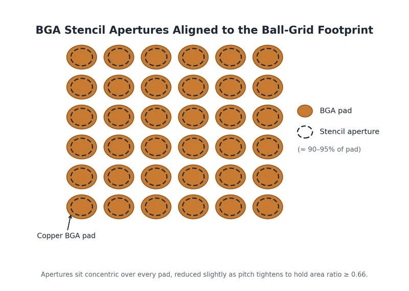
BGA stencil apertures aligned to a ball-grid footprint.
Why BGA Stencil Design Is Critical
A BGA hides its joints under the body of the package. You cannot inspect them by eye, and you cannot touch up a marginal joint with an iron. Rework means pulling the whole part and reballing it.
Because inspection depends on X-ray and rework is expensive, the paste deposit has to be right on the first print. Paste volume alone decides whether you get a clean joint, a bridge, a void, or a starved ball.
On fine-pitch BGAs the limiter is almost never reflow heat. It is the area ratio of the aperture. Print too little paste and the balls land on insufficient joints; print too much and adjacent deposits merge into bridges once the balls collapse.
That narrow window is why a fine-pitch build is won or lost at the stencil, not the oven.
The Two Ratios Behind Every Aperture (Briefly)
Two numbers decide whether paste releases from an opening. The aspect ratio (aperture width divided by stencil thickness) should stay at or above 1.5, and the area ratio (the opening's area divided by the area of its aperture walls) at or above 0.66, which for a round BGA aperture simplifies to diameter ÷ (4 × thickness). Below 0.66 the paste starts clinging to the walls instead of transferring to the pad, so every rule that follows (thinner foil, reduced apertures, better wall finishes) exists to protect that number. Our stencil design guidelines carry the full derivation.
BGA Aperture Design by Ball Pitch
Aperture sizing is a balance: open enough to deposit the paste volume the ball needs, but reduced enough to hold the area ratio and keep clearance to the next pad. As pitch tightens, the balance shifts toward smaller apertures.
The table below gives practical starting points. JLCPCB's CAM can refine these automatically, but knowing the targets lets you design deliberately.
Table 1: Aperture sizing by BGA ball pitch
| BGA Ball Pitch | Aperture Sizing | Notes |
|---|---|---|
| > 1.0 mm | 1:1 with the pad, or reduce ~0.05 mm | Generous margin; round apertures are fine |
| 0.5–1.0 mm | Near 1:1, watch the area ratio | Slight reduction if bridging risk is high |
| < 0.5 mm (µBGA/CSP) | Reduce to ~90–95% of the pad | Consider square apertures with radiused corners |
| Ceramic BGA | Slightly larger (~+0.05–0.08 mm) | Offsets CTE / thermal-expansion mismatch |
The square-aperture trick for µBGA and CSP parts is widely misunderstood, so it is worth stating precisely. A square opening does not beat a circle on area ratio simply by being square: for a square and a circle of the same width, both work out to W ÷ (4 × thickness), because the perimeter grows in step with the area.
The gain comes from the corners. Rounding them trims wall length slightly faster than it trims open area, which lifts the area ratio by roughly 5% at a corner radius near a quarter of the width. That is a modest margin, but at 0.4 mm pitch it is often the difference between releasing and clogging, and it costs no extra footprint.
Round apertures remain the sensible default for larger pitches, where area ratio is not the constraint. Home-plate and D-shaped openings belong to small chip components, not BGAs, so leave them out of a ball-grid layout.
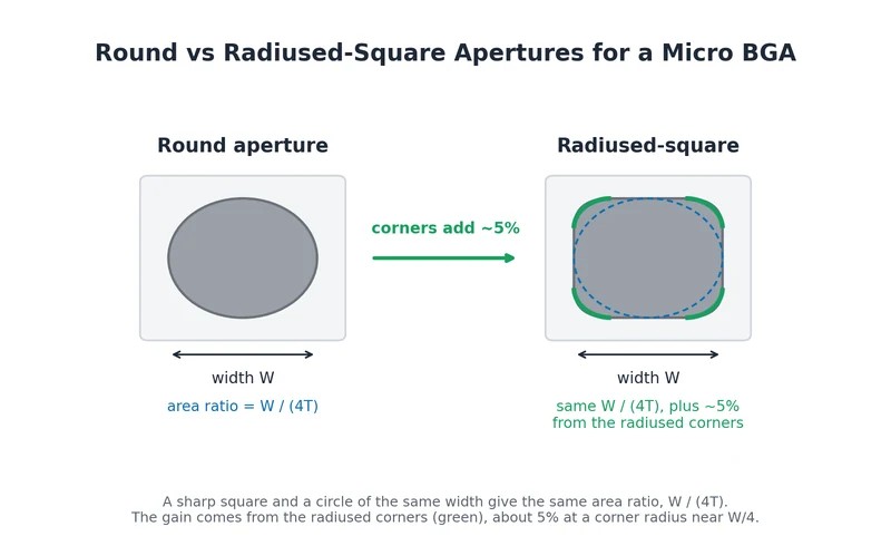
Round vs radiused-square apertures: the area-ratio gain comes from the radiused corners, not from squareness.
Choosing Stencil Thickness for BGA
Thickness is the other half of the area-ratio equation, and the rule is simple: the finest ball pitch on the board sets the foil. Thicker foil deposits more paste but hurts release on small apertures, while thinner foil releases cleanly but starves large openings.
The table below pairs pitch with a sensible starting foil thickness.
Table 2: Stencil foil thickness by BGA ball pitch
| BGA Ball Pitch | Recommended Foil Thickness |
|---|---|
| > 1.0 mm | ~0.15 mm |
| 0.5–1.0 mm | ~0.13 mm (drop to 0.10–0.12 mm at the 0.5 mm end) |
| < 0.5 mm | ~0.10–0.12 mm (thinner to keep area ratio ≥ 0.66) |
Treat these as starting points, not verdicts, and always compute the area ratio on your smallest aperture. A 0.5 mm pitch part with 0.25–0.30 mm apertures lands at 0.52–0.63 on 0.12 mm foil, which is under target, and that is why those boards usually end up on 0.10 mm.
The complication is mixed boards. If the same panel carries a fine-pitch BGA and a large connector that needs far more paste, one flat foil cannot satisfy both. Let the finest-pitch part set the base thickness, then use a step stencil where the hungry parts sit.
JLCPCB's standard foil range runs 0.10–0.20 mm, with a special range down to 0.03 mm and up to 0.5 mm, which covers almost any mix. When a board genuinely needs two thicknesses, our step stencil options are the clean way to do it.
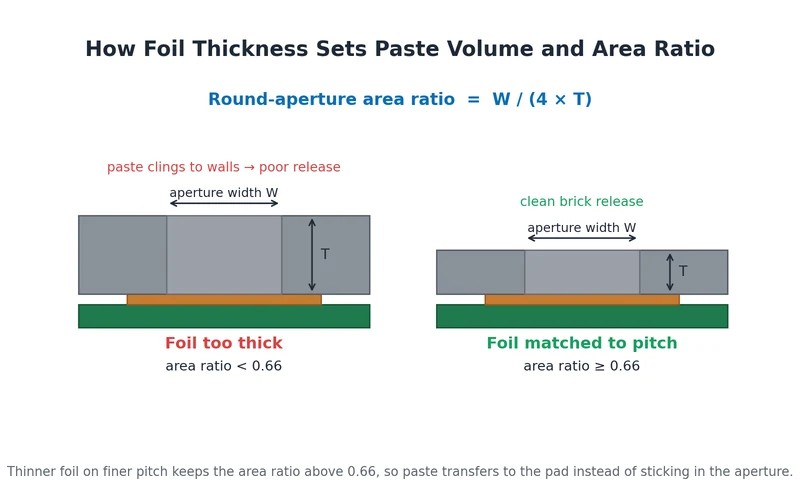
How foil thickness sets paste volume and area ratio.
Fine-Pitch and µBGA/CSP: When Standard Rules Break
At 0.4 mm pitch the standard rules start to fail. Even with thin foil, the achievable area ratio often lands between 0.56 and 0.75. Anything below 0.66 is a compromise zone rather than a comfortable design point: printable, but only with a polished, coated wall and tight process control. Near the bottom of that band, paste under-releases and apertures clog print after print.
This is the hardest BGA case on a normal line, where careless aperture math yields joints that pass a quick look and fail in the field.
The fixes stack. Go thinner on the foil to lift the area ratio. Switch round apertures to radiused-square ones, which buys roughly 5% more area ratio at the same width once the corners are rounded.
And lean on the aperture wall finish, because at this scale the wall matters as much as the geometry. Electropolishing is effectively required below 0.5 mm pitch to smooth the cut walls, and a nano-coating on top of electropolishing further improves release by making paste let go of the walls more willingly.
Via-in-Pad Under a BGA
Via-in-pad is common under BGAs because it lets you route escape traces straight down from the ball, but an open via is a trap for paste. During reflow the paste wicks down the barrel, pulling volume away from the joint and leaving starved balls and internal voids.
The fix belongs at fabrication, not at the stencil: the vias should be filled or plugged and then capped or plated over, so the pad reflows like any solid pad and the stencil prints normally.
If for some reason the vias are left open, the stencil has to compensate: web the aperture or reduce it over the via so less paste sits directly above the hole. That is a workaround, not a cure, and filling and capping is the reliable route. Our overview of via-in-pad technology walks through the fabrication side in detail.
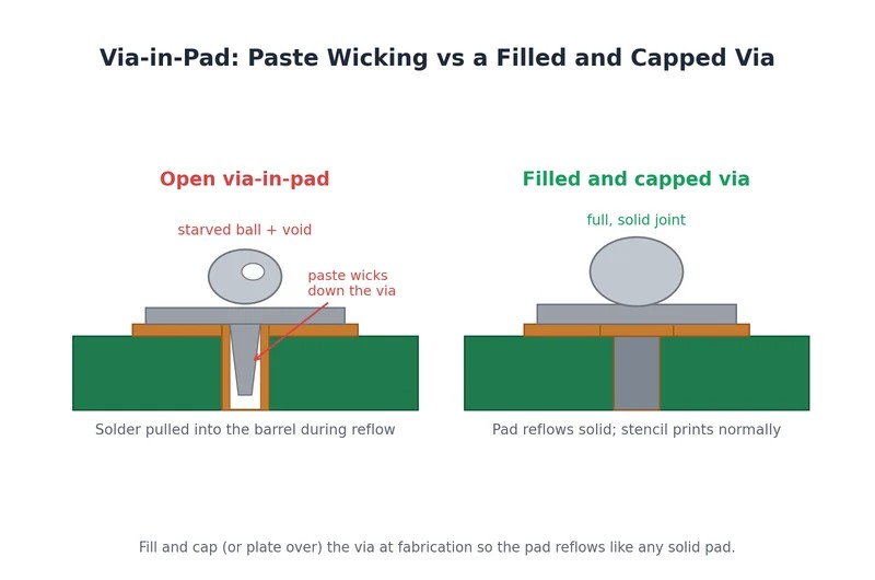
Paste wicking into an open via versus a filled and capped via-in-pad.
Fiducials and Alignment
A BGA demands tight print registration, because a small offset between paste and pad shows up as off-centre deposits that push balls toward their neighbours. Give the printer something precise to align to by including two or three fiducial apertures in the stencil that mirror the fiducials on the PCB.
The machine reads those marks and aligns paste to pads far more accurately than it can from board edges alone. Placement and mark style follow the usual rules, and our note on SMT stencil fiducials covers the specifics.
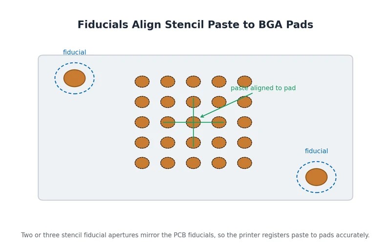
Fiducial marks aligning stencil paste to BGA pads.
Design It Yourself, or Let the CAM Optimize It
You do not have to compute every aperture by hand. Most stencil makers optimize apertures for you, and JLCPCB's CAM applies an opening-process standard by pitch to the paste layer by default, reshaping apertures to the targets above. You can opt out and keep them exactly as drawn if you would rather control them yourself.
So there are two honest paths. Design the apertures with the rules above and opt out of auto-optimization, or upload your paste layer as-is and let the CAM apply its pitch-based standard. Either way it runs through the same precision stencil manufacturing line, and the area ratio is what you are protecting, so verify the result before you commit.
Common BGA Stencil Mistakes and Fixes
Most BGA print problems trace back to a handful of design slips. Each follows the same shape: a design choice, the paste behaviour it causes, and the fix.
Mistakes to Avoid
- 1:1 apertures on fine pitch → bridging or excess paste once balls collapse → reduce to ~90–95% and go to thinner foil.
- Foil too thick for the pitch → too much paste volume → bridging or solder balls → match thickness to the finest ball pitch.
- Area ratio below 0.66 → starved or clogged apertures → thinner foil, radiused-square apertures, electropolish plus nano-coating.
- Open via-in-pad → paste wicks down the barrel → fill and cap the vias, or web the aperture over the hole.
- Round apertures on µBGA → leaving the ~5% corner gain unused when area ratio is marginal → switch to radiused-square apertures.
- Skipping wall finish on fine pitch → rough walls, poor release → electropolish (and add nano-coating) for clean transfer.
For a broader look at what goes wrong at the print step and how to read the symptoms, see our guide to solder paste printing defects.
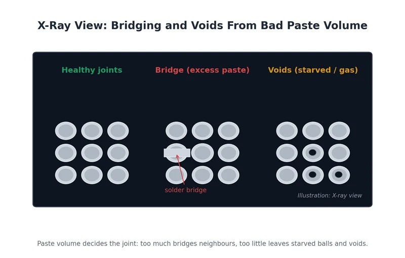
X-ray view (illustration): bridging and voids from bad paste volume.
FAQs About BGA Stencil Design
Q: What Stencil Thickness Should I Use for a 0.5 mm Pitch BGA?
Start at 0.12 mm foil for a 0.5 mm pitch BGA, then check the area ratio for your pad size. With a 0.25–0.30 mm aperture, 0.12 mm gives 0.52–0.63, which is below the 0.66 target, so most 0.5 mm pitch boards end up on 0.10 mm. Run the numbers on your smallest aperture before you commit.
Q: Should BGA Apertures Be Round or Square?
Round apertures are the default and work well down to about 0.5 mm pitch. Below that, radiused-square apertures earn their place, though not for the reason usually given: a sharp square and a circle of the same width have exactly the same area ratio, W ÷ (4 × thickness). The benefit comes from the rounded corners, which lift the area ratio by roughly 5% at a radius near a quarter of the width. Keep the corners radiused, never sharp.
Q: What Is the Minimum Area Ratio for a BGA Stencil?
The working target is 0.66, the value IPC-7525 uses for reliable paste release. Below it, paste starts clinging to the aperture walls instead of transferring to the pad, and deposits become erratic. Between 0.56 and 0.66 you are in a compromise zone that can be printed with electropolishing and nano-coating, but it is not a comfortable design point. If a BGA aperture falls under target, the usual moves are thinner foil, radiused corners, and a polished wall.
Q: Do I Need a Different Stencil for Via-in-Pad BGAs?
Not a different stencil, but a different fabrication choice. Via-in-pad problems are solved at the board: fill, plug, and cap or plate the vias so each pad reflows solid, and the stencil then prints normally with standard apertures. Only if the vias must stay open do you touch the stencil, webbing or reducing the aperture over the hole to limit paste wicking.
Q: Why Does My Fine-Pitch BGA Keep Bridging?
Bridging on a fine-pitch BGA usually means too much paste for the clearance: foil too thick, apertures too close to 1:1, or both. Reduce the apertures toward 90–95% of the pad and drop to a thinner foil so the deposited volume shrinks. Verify print registration too, since an offset print pushes deposits toward neighbouring pads and mimics a paste-volume problem.
Q: Can I Let JLCPCB Optimize the Apertures for Me?
Yes. JLCPCB's CAM applies a pitch-based opening-process standard to your paste layer by default, reducing and reshaping apertures to sound targets automatically. If you would rather keep full control, opt out and the apertures stay exactly as you drew them. Either way, confirm the area ratio on your finest-pitch parts before committing to the build.
Conclusion: Get the BGA Stencil Right the First Time
BGA stencil design comes down to a few disciplined choices. Thickness follows the finest ball pitch, apertures shrink as pitch shrinks while you hold the area ratio at or above 0.66, µBGA and CSP parts lean on radiused corners and a polished wall finish, and via-in-pad has to be filled and capped at fabrication rather than patched at the stencil.
Get those right and the hidden joints under the package reflow clean.
From there you have two paths. Design the apertures with the rules above and opt out of auto-optimization, or upload your paste layer and let the CAM apply its pitch-based standard. Either way, verify the area ratio on your tightest pitch before you commit the order. A stencil is inexpensive, and a reworked BGA is not.
Keep Learning
BGA Stencil Design: Apertures, Thickness & Tips
On a ball grid array, every solder joint hides underneath the package where you cannot see it, touch it, or easily rework it. That is exactly why BGA stencil design decides whether the board works: the paste you print is the paste you get, and a print that is slightly too heavy or too light turns into hidden bridges, voids, or starved balls that only an X-ray will reveal. Get the stencil right and the joints reflow clean the first time. Get it wrong and you are chasing intermittent faults after assemb......
Stencil Aperture Design: Geometry, Area Ratio & Tips
Key Takeaways Stencil aperture design controls paste volume, deposit shape, and print registration — it's the key controllable variable in SMT print quality. As per IPC-7525B, two math rules are non-negotiable: stencil area ratio ≥ 0.66 and stencil aspect ratio ≥ 1.5. Aperture geometry is component-dependent: 1:1 with pad for BGA, window-pane splits for QFN/BGA thermal pads, home-plate shapes for 0201/01005 chips, and modest reductions for fine-pitch QFP. Aperture reductions intentionally decrease the......
Red Glue Stencil: Types, Thickness & Ordering Guide
Key Takeaways A red glue stencil deposits adhesive dots under component bodies, not solder paste on electrical pads. Its main use is holding bottom-side SMD parts during wave soldering of through-hole leads. SMT red glue is commonly dyed red so operators can confirm each deposit during inspection. Printable adhesive families include epoxy, acrylic, and UV- or dual-cure materials. Glue stencils are commonly thicker than paste stencils because the dot must reach the component underside. A custom o......
DFN Package Guide: Footprint, Soldering & Stencil Tips
Key Takeaways What a DFN is: A DFN (Dual Flat No-Lead) package is a leadless chip-scale IC package with connection pads on two opposing sides of its underside, usually plus a central exposed thermal pad. Assembly requirements: DFN joints sit hidden under the body, so it needs reflow soldering with a stencil and X-ray or AOI inspection, not hand soldering. Design essentials: Follow IPC-7351 land patterns and IPC-7525 aperture rules, use a thinner stencil foil around 0.1-0.12 mm, and segment the thermal......
A Beginners Guide to Step-Up and Step-Down Stencils
As everyone knows, companies are moving down to 2nm, and electronics are at their peak right now. The component sizes of a PCB likewise drastically shrink during a ten-year period. From 1206, BGAs have shrunk to 0402, 0201, and even smaller. Due to the small size of the components and the requirement for high throughput, defects such as tombstoning, bridging, or poor connections may occur during the soldering process. To address these challenges, specialized stencil technologies such as step-up and st......
Design Guidelines for Industry-Standard Solder Stencil
Solder paste printing is one of the most important processes in PCB assembly, and the design of a stencil directly affects the quality of solder paste application. In a previous article, we discussed stencils and their types in detail. JLCPCB’s advanced stencil options, including step-up/step-down and nano-coated stencils, help engineers achieve higher printing accuracy and assembly reliability. In electronics hardware design, following proper design rules is just as crucial as having the right tools.......