
SMT Stencil Fiducial: Types, Design Rules, and Placement
11 min
- What Is a Stencil Fiducial?
- Stencil Fiducial vs. PCB Fiducial: What's the Difference?
- Decoding the Three Fiducial Options for SMT Stencils
- Design Standards and Placement Strategies (IPC-7525)
- How to Use Fiducials for Reliable SMT Printing
- Ordering SMT Stencils with Custom Fiducials at JLCPCB
- FAQ about SMT Stencil Fiducials
- Conclusion: Mastering SMT Stencil Fiducials for High-Yield Assembly
Key Takeaways
Alignment accuracy is critical: Even a ±0.003 mm precision stencil will produce defective boards if misaligned by 50 microns — fiducials are the only way to prevent this.
Half-etched (blind) fiducials are the professional standard: They deliver maximum optical contrast without paste contamination risks, ideal for pitches below 0.5 mm.
Three-point triangulation is essential for fine-pitch: Two fiducials correct X, Y, and rotation, but only a third enables scaling compensation to catch FR4 stretch.
304 HTA stainless steel prevents warpage: Tension-annealed steel eliminates residual stresses that cause foil lift between fiducial points, ensuring consistent inter-fiducial distance across 10,000+ print cycles.
Solder paste deposition causes 60% to 70% of all surface mount technology (SMT) assembly defects. While engineers spend considerable time planning trace layouts or reflow profiles, they often overlook a critical factor: ensuring the stencil and the PCB share the exact same optical coordinate system.
Precision manufacturing alone cannot save a misaligned production run. Even a stencil cut to a strict ±0.003 mm precision will result in defective boards if it is misaligned with the PCB by just 50 microns.
On a 0.4 mm pitch BGA, a minor 50-micron shift causes immediate solder bridging. Stencil fiducials eliminate this risk. They provide stable, high-contrast reference points that allow the printer's vision system to calculate and correct X, Y, and rotational offsets instantly before printing.
What Is a Stencil Fiducial?
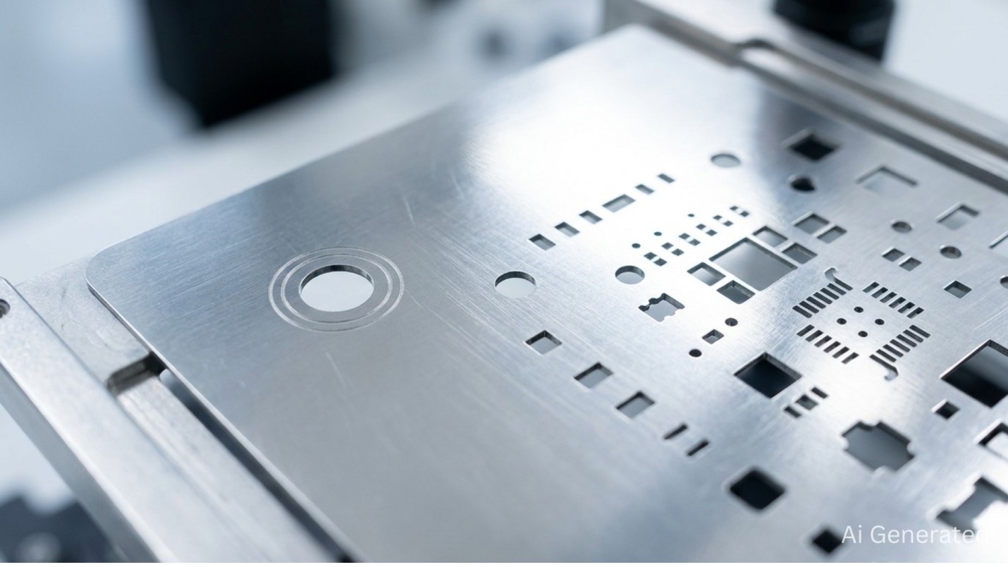
A stencil fiducial is a non-functional reference mark laser-cut into the stainless steel foil. Unlike apertures, it does not transfer solder paste to the circuit board. Its purpose is purely optical. It provides a high-contrast target so the automated alignment system can locate the exact center of the mark down to the sub-pixel level.
Modern SMT printers use advanced CMOS or CCD cameras paired with edge-detection algorithms. During the alignment phase, the machine utilizes a split-vision camera system:
- The downward-looking camera reads the fiducials on the PCB copper layer.
- The upward-looking camera reads the matching fiducials on the stencil foil.
The printer software cross-references these coordinates. If any deviation is found, high-response linear servo motors adjust the stencil's position before the squeegee stroke executes. For 0402 passives and 0.3 mm pitch BGAs, this real-time alignment determines the difference between a high-yield run and a scrap pile.
Stencil Fiducial vs. PCB Fiducial: What's the Difference?
Both markers are vital to automated assembly lines, but they serve different production stages.
PCB fiducials are etched copper circles exposed directly through the solder mask. They act purely as optical targets for the pick-and-place machine to accurately register the board layout before populating components.
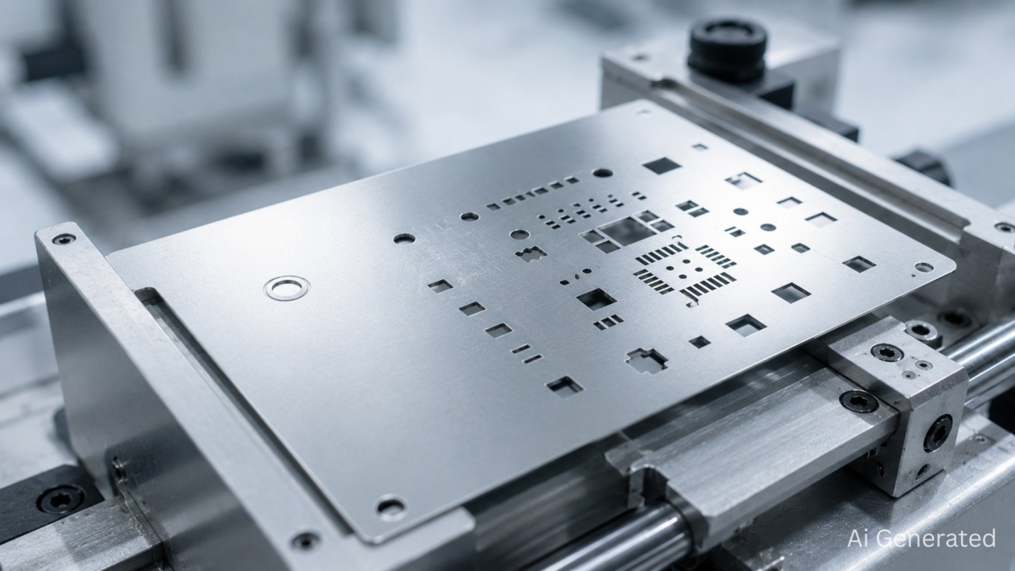
Conversely, stencil fiducials are laser-cut directly into the steel sheet. They align the stencil apertures directly with the board's surface pads right before paste application.
| PCB Fiducial | Stencil Fiducial | |
|---|---|---|
| Material | Copper (ENIG / HASL / OSP) | 304 HTA Stainless Steel |
| Read by | Pick-and-Place machine | SMT Printer vision system |
| Positional tolerance | Tied to the copper layer registration | ±10μm relative to apertures |
| Contrast source | Reflective copper vs. matte substrate | Recessed etching vs. polished foil |
Decoding the Three Fiducial Options for SMT Stencils
Choosing a fiducial style is a process-reliability decision that dictates how well your vision system performs.
1No Fiducial: The Prototyping Baseline
Without optical marks, automated alignment is impossible. Assembly relies on manual methods like a jeweler's loupe, tape fixturing, or manual jig setups. This approach is fine for prototypes containing 0603 or larger passives. However, manually maintaining sub-micron alignment across an entire board surface is highly unrealistic for fine-pitch layouts below 0.4 mm.
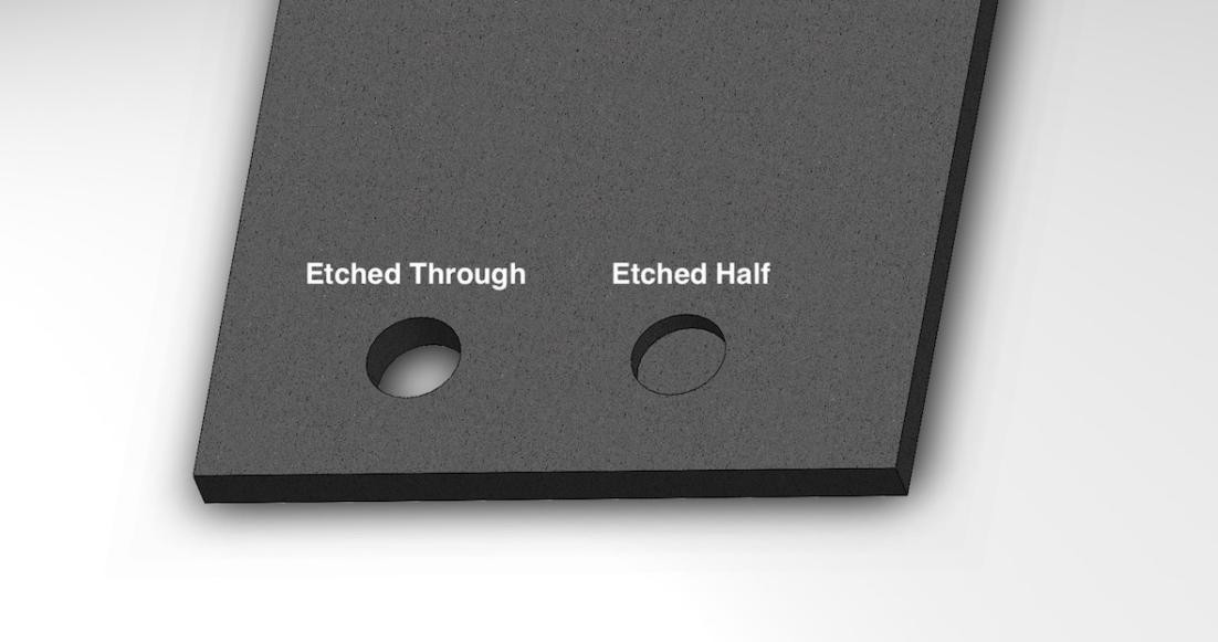
2Etched Through (Laser-Cut): High Contrast, High Risk
These marks are clear holes cut entirely through the steel foil. The raw background contrast creates a distinct "black hole" appearance that older vision systems can find easily.
Risks of Through-Cut Fiducials
- Solder paste can squeeze through the open hole and deposit onto the PCB's copper fiducials during a print cycle.
- Stray paste blocks pick-and-place cameras and smears the printer's optical lenses.
- Causes expensive cleaning downtime in production environments.
3Half-Etched (Blind): The Professional Standard
This style is the professional industry standard. The markers are laser-engraved into the bottom surface of the foil facing the board. The squeegee side remains completely solid, creating a physical barrier that prevents paste leakage.
The laser engraving process micro-roughens the interior of the recessed pocket. Under machine ring-lights, this diffuse surface scatters light efficiently, creating a dark, highly distinct shape that stands out sharply against the shiny surrounding steel foil. This design delivers maximum optical contrast without contamination risks.
Precision Note
Half-etched fiducials at JLCPCB are geolocated with an accuracy of ±0.003mm — ideal for ultra-fine pitch assembly such as 0.3mm-pitch BGA.
Design Standards and Placement Strategies (IPC-7525)
The geometry and placement rules required for reliable stencil fiducials across various machine platforms and production lots are defined in IPC-7525 or Stencil Design Guidelines.
Geometry
Circles are preferred. They are rotationally symmetric and enable center-of-gravity algorithms to determine the exact center of the mark from any angle of illumination. Standard diameter: 1.0–1.5 mm. The mark must be surrounded by a "quiet zone" of the same diameter as the fiducial, allowing no apertures, traces, or silkscreen within that zone.
Global vs. Local Fiducials
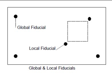
Global fiducials at board corners correct overall X, Y, and rotational offsets. For high-pin-count devices (0.5 mm BGA, fine-pitch QFPs), local fiducials placed diagonally around them compensate for localized warpage that cannot be detected by the global marks.
The Three-Point Triangulation Method
Two fiducials measure X, Y, and θ offset, but do not measure scaling. During lamination and thermal cycling, FR4 substrates tend to stretch. A 20-micron separation between two marks worldwide is undetectable, leaving inaccuracies in apertures on the edge of the board but seemingly correct in the center.
This is solved by three fiducials arranged in an "L" pattern, but not symmetric. The machine detects stretch, non-linear distortion, and 180° orientation errors.
| Alignment Technique | X-Y Correction | Rotation (θ) | Scaling / Stretch |
|---|---|---|---|
| Manual (No Fiducials) | Poor (human error) | Poor | None |
| 2-Point Alignment | Excellent | Excellent | None |
| 3-Point Triangulation | Excellent | Excellent | Excellent |
How to Use Fiducials for Reliable SMT Printing
The Automated Alignment Workflow
The printer takes a PatMax image for initial orientation of the board. Ring lights from LED are calibrated to maximize the contrast of the edges of the fiducials.
The vision system maps the pixel coordinates to real-world millimeters, and high-response linear servo motors compensate for the X-Y-θ correction.
In preparation for the squeegee stroke, the support platen raises the board into contact with the bottom of the stencil with an error range of 10–20 microns.
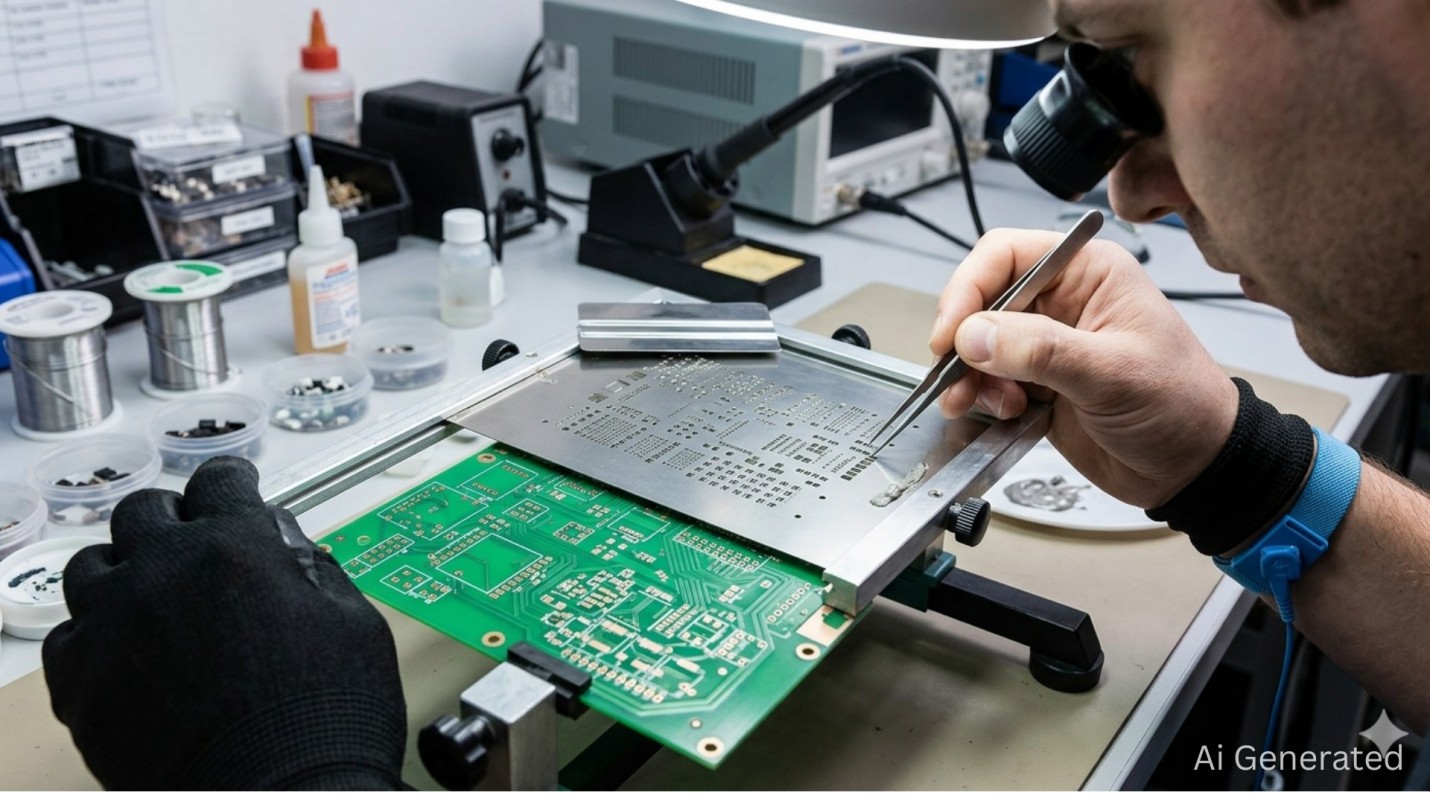
Manual Alignment for Lab Setups
The accuracy of a split-vision microscope overlay is ±25 µm, which is enough for 0.5 mm-pitch devices. Rapid board swaps with stencil registration are possible with a dummy-board fixture jig made with Kapton tape.
Why 304 HTA Stainless Steel Matters
Residual stresses are present in standard 304 steel due to cold rolling. The stresses are not evenly released in the laser cutting process, and this leads to "potato chip" warpage, which causes the foil to lift from the PCB between fiducial points.
304 HTA (Tension Annealed) steel is grade 304 austenitic stainless steel that has been cold-rolled to full-hard temper, then tension-annealed at a low temperature so internal stresses are relieved without softening the foil. The hardness, rigidity, and elasticity of the full-hard temper are preserved, while the residual stresses that cause warpage are released.
The result: a constant inter-fiducial distance, flatness, and up to 10,000+ print cycles — with easy resistance to squeegee abrasion ensuring the fidelity of the optical image of the fiducials throughout their service life.
Ordering SMT Stencils with Custom Fiducials at JLCPCB
JLCPCB has more than 30 LPKF fiber laser cutting machines, and the fiducial marks and apertures can be processed with a precision of ±0.003 mm. The base material is only 304 HTA stainless steel.
Here's how the JLCPCB stencil ordering workflow works:
Upload Gerber Data and Configure Base Parameters
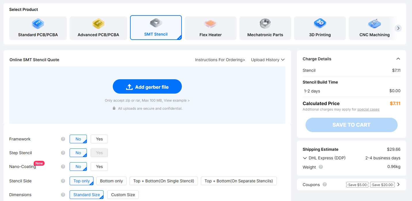
Upload your Gerber files. To define the geometry of the aperture, the system needs the Solder Paste Layer.

You can select thickness from the expert team of JLCPCB engineers in the "Select by JLCPCB" section or choose the custom thickness as per your required needs.
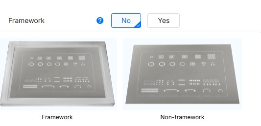
There is also a choice between Frameless and Framed — Framed is ideal for high-speed automated printers.
Specify Custom Fiducial Strategy

As per IPC-7525, fiducials are the "eyes" of the assembly line. Configure your markers based on your equipment's capabilities:
-
Etched Half (Board Side): The professional standard. These are laser-engraved pockets that provide high-contrast optical signatures for "look-up" cameras without allowing paste leakage.
Etched Through: Holes cut through the foil. Recommended only for older vision systems or manual alignment, where the "black hole" effect is necessary for visibility.Final Review and Remark Instructions
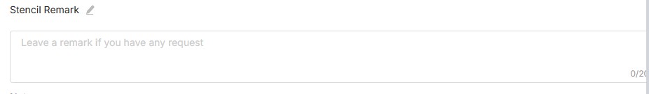
Before checkout, use the "Remark" field for hyper-specific manufacturing requests:
-
Specify exact etch depths (e.g., "Half-etch fiducials to 0.05mm depth").
Request "Step-up" or "Step-down" areas if your board combines large power components with ultra-fine-pitch BGAs.By integrating these technical specifications, you leverage a manufacturing ecosystem capable of 0.003 mm accuracy, starting at $3 USD with build times as fast as 12 hours.
Choose from Framed/Frameless, Electropolishing, Nano-coating, Step-Stencils, SMD Glue Stencil and more. Starting at $3. No MOQ. 12-Hour production.
Get $11 Coupon Now >
FAQ about SMT Stencil Fiducials
Can I use PCB fiducials instead of stencil fiducials for printer alignment?
Yes, SMT printers can use PCB fiducials, but they do not replace stencil fiducials. The printer's downward-looking camera reads the PCB fiducial (referenced to the copper layer), while the upward-looking camera reads the stencil fiducial (referenced to the apertures). The system calculates the offset between them to align the stencil to the board, so both sets of fiducials are needed to correct board-to-stencil registration error rather than introduce it.
How many fiducials does my stencil need?
A minimum of three global fiducials is strongly recommended for any board with components with a pitch below 0.5 mm. Two fiducials correct X, Y, and θ, but cannot detect board stretch. A third enables triangulation and full scaling compensation — the only way to guarantee alignment accuracy at board edges.
Do half-etched fiducials require special cleaning?
Yes. Half-etched fiducials need gentle cleaning because aggressive wiping can damage the fine engraved texture that provides optical contrast. Ultrasonic cleaning can also wear them over time via cavitation, and when detergent is used, it is typically SMT-compatible and mildly alkaline (pH 9–11).
What causes "Fiducial Not Found" errors on the SMT printer?
A frequent cause is paste contamination from etched-through fiducials. Dried paste inside the holes alters their optical profile, preventing the vision system from achieving a confident pattern match. Switching to half-etched (blind) fiducials eliminates this failure mode entirely, as the solid squeegee-side surface prevents any paste from entering the mark.
Conclusion: Mastering SMT Stencil Fiducials for High-Yield Assembly
Stencil fiducials are the eyes of the SMT process — the reference points that translate a designer's coordinate intent into machine-executable alignment. When they are missing, contaminated, or the wrong type, every downstream process compensates for a problem it cannot see.
For prototyping, through-cut or no fiducials are workable. For any production environment running at a pitch below 0.5 mm, half-etched marks on 304 HTA stainless steel, arranged in three-point triangulation per IPC-7525, are the only reliable path to consistent first-pass yield.
Combined with a precision manufacturer capable of ±0.003 mm fiducial accuracy, the "precision gap" between digital design and physical assembly becomes effectively zero.
Keep Learning
Solder Paste Printing Machine Guide: Selection, Settings & Stencil Optimization
Key Takeaways at a Glance A solder paste printing machine forces paste through stencil apertures onto PCB pads, setting the volume and registration that every later stage depends on. Printing is where most SMT defects begin — industry studies commonly attribute more than half of assembly defects to the paste-print stage. Manual printers fit prototypes and low volume, semi-automatic suits mid-volume EMS work, and fully automatic inline systems handle continuous, high-throughput production. Typical indu......
Step Stencil Design: The Complete Technical Guide
Key Takeaways A multi-level stencil places different foil thicknesses in distinct zones—thinner for fine-pitch components, thicker where high-mass joints need more paste volume. Typical step depths run 0.025 mm to 0.05 mm (25–50% of base foil thickness). Exceeding 50% risks mechanical failure, foil fatigue, and print inconsistency. Maintain 1.5–2.0 mm clearance between any aperture and the nearest step edge to prevent squeegee bounce, paste scooping, and volume variation. Modern step stencil manufactu......
SMT Stencil Fiducial: Types, Design Rules, and Placement
Key Takeaways Alignment accuracy is critical: Even a ±0.003 mm precision stencil will produce defective boards if misaligned by 50 microns — fiducials are the only way to prevent this. Half-etched (blind) fiducials are the professional standard: They deliver maximum optical contrast without paste contamination risks, ideal for pitches below 0.5 mm. Three-point triangulation is essential for fine-pitch: Two fiducials correct X, Y, and rotation, but only a third enables scaling compensation to catch FR4......