Navigating Automotive PCB Manufacturing Standards and High-Reliability Fabrication
15 min
- The Evolution and Demands of Automotive PCB Applications
- Core Automotive PCB Manufacturing Standards and Quality Systems
- Engineering Considerations for Custom PCB Design for Automotive
- Rapid Prototyping and SMT Assembly for Smart Vehicles
- JLCPCB's Automotive-Grade PCB Manufacturing Excellence
- FAQs about Automotive PCB
- Conclusion
Key Takeaways
- Harsh Operating Environments: Engineered to survive 15 years under thermal cycling (-40 °C to 150 °C) and severe vibration.
- Strict Compliance: Guided by IATF 16949, AEC-Q200 components, and IPC Class 3 standards.
- Targeted Materials: Leverages high-Tg/heavy copper for power and Rogers substrates for 77 GHz radar.
- Zero-Defect Inspection: Employs 3D AOI and X-ray testing to eliminate hidden solder joints failures.
An automotive PCB has to keep working for fifteen years in the same place. Bolted near the engine, it meets minus 40 °C on a winter morning, and 125 °C twenty minutes later. Once you multiply that by 100,000 cycles, the design problem changes completely. The repetition is the real problem, and it explains why automotive standards look the way they do. Epoxy resin expands along the z-axis several times faster than the copper inside a via, so each heating cycle slightly stretches the plated barrel.
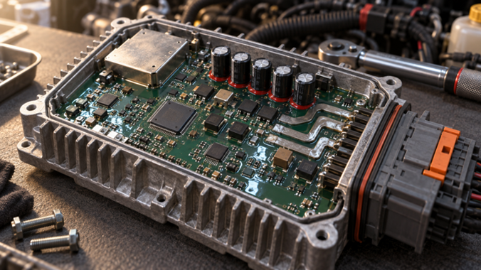
Figure 1: An automotive engine control unit PCB inside its sealed aluminum housing
The copper simply thins where it was already weakest until, on some cold morning in year eight, the connection opens. Design against that slow failure, and most other requirements fall into place, because nearly every automotive rule exists to delay it. This guide covers the standards governing automotive board work and the environments that gave rise to them.
The Evolution and Demands of Automotive PCB Applications
A car built in 1995 carried a few relays, a radio, and one engine controller. A current model carries over a hundred processors, but the boards running them sit in locations no consumer product would survive.
Key Drives: Powertrain Electrification, ADAS, and Smart Cabins
Electrification changed the electrical problem completely. A 400 V or 800 V traction system pushes hundreds of amps through the inverter and the battery management board. Copper weight and creepage distance therefore, drive the layout. Signal-integrity habits do not help here, because the binding constraints are heat and insulation rather than timing.
- ADAS hardware pulls in the opposite direction, toward frequency instead of current. A forward radar module built on the Texas Instruments AWR2944 operates across the 76-81 GHz band.
- Every touchscreen, camera feed, and lighting module needs its own board, so they talk over CAN buses driven by transceivers such as the NXP TJA1051. The reversing camera you rely on in a car park is one node on that network.
Harsh Operating Environments: Thermal Shock, Vibration, and Moisture
Temperature is the first constraint, and it depends entirely on where the module is bolted. A board in the cabin might reach 85 °C, while one clamped to the engine block might reach 150 °C. Above its glass transition temperature, FR-4 expands vertically far faster than the copper barrel does, so every heat cycle stretches that barrel. Nothing fails in cycle one, which is why automotive qualification counts cycles rather than peaks.’
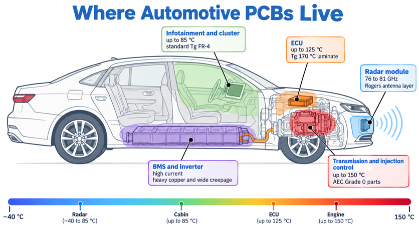
Figure 2: Vehicle zone map showing where each electronic module sits
Vibration attacks a different set of joints. ISO 16750-3 tests road vehicle electronics from 10 Hz to 2,000 Hz. Its harshest profiles are reserved for anything mounted on the engine or gearbox. Tall electrolytic capacitors and heavy connectors are the first to crack, so they get staked or mechanically anchored.
Moisture works slowly and invisibly. Condensation inside a sealed housing, combined with a bias voltage, can grow a copper filament along the glass bundles between two vias.
| Mounting Zone | Typical Ambient | Component Grade Needed | What This Means for Your Board |
|---|---|---|---|
| Cabin and dashboard | Up to 85 °C | AEC-Q100 Grade 3 parts | Standard Tg FR-4 is usually acceptable |
| Chassis and body | Up to 105 °C | Grade 2 parts | Tg 150 °C laminate, staked tall components |
| Engine compartment | Up to 125 °C | Grade 1 parts | Tg 170 °C laminate, Class 3 via copper |
| On the engine or gearbox | Up to 150 °C | Grade 0 parts | Tg 170 °C or higher, harshest ISO 16750-3 profile |
| Battery pack and inverter | 85 to 105 °C at high current | Grade 1 parts | Heavy copper, wide creepage, reinforced isolation |
Peak temperature determines which laminate you may use, while cycle count determines whether the board survives.
Core Automotive PCB Manufacturing Standards and Quality Systems
Automotive quality gets enforced in two separate places, because a certified factory and a qualified component are entirely different things. One covers the system that builds the hardware, and the other covers the parts that go onto it.
IATF 16949 Certification and AEC-Q200 Component Requirements
IATF 16949:2016 is a quality management system standard, built on ISO 9001:2015 with automotive requirements layered on top. Those additions are what matter: APQP for launch planning, PPAP for part approval, FMEA for risk analysis, and SPC for process monitoring. It certifies how a factory runs, which means it says nothing about what comes out of it.
AEC-Q200 is often misunderstood. It is an Automotive Electronics Council qualification standard for passive components such as resistors, capacitors, inductors, fuses, varistors, and resonators. It defines environmental and electrical stress tests for those components. A bare PCB cannot be AEC-Q200 qualified, because the standard does not cover PCB laminates, fabrication, or board construction. So the checking work sits at the component level, one line item at a time. Pull a 100 nF 0603 capacitor from the JLCPCB parts library, and the question is whether that exact part number carries an AEC-Q200 report.
Strict IPC Class 3 Standards for Zero-Defect Performance
IPC-6012 is the qualification and performance specification for rigid boards, and it defines the three product classes.
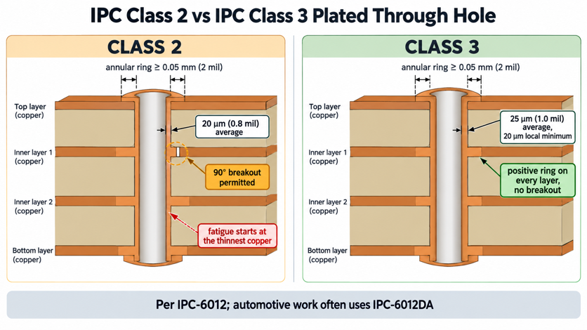
Figure 3: Microsection comparison of an IPC Class 2 and an IPC Class 3 PTH
Class 1 covers general electronics, Class 2 covers dedicated service equipment, and Class 3 covers hardware for which failure is unacceptable. IPC-A-600 is its visual companion, which means it describes what a defect looks like rather than what performance is required. Automotive work usually lands on Class 2 with selected Class 3 requirements, or on IPC-6012DA, the automotive addendum.
| Requirement | IPC Class 2 | IPC Class 3 | What It Costs You |
|---|---|---|---|
| Plated barrel copper | 20 µm (0.8 mil) average | 25 µm (1.0 mil) average, 20 µm minimum | Longer plating cycle, higher price |
| Annular ring | 0.05 mm (2 mil), internal breakout allowed | 0.05 mm (2 mil), no breakout on any layer | Larger pads, fewer routing channels |
| Etched conductor width | Minus 20% of nominal | Minus 20%, with tighter defect limits | Wider design rules on fine traces |
| Coupon verification | Sampled | Every panel, microsectioned | Longer lead time on the first build |
| Typical use | Infotainment, comfort, and lighting | Airbag, braking, steering, powertrain | Apply Class 3 only where it earns its place |
Class 2 asks whether the board works when it ships, while Class 3 asks whether it still works after ten years of thermal cycling.
Engineering Considerations for Custom PCB Design for Automotive
Two physical demands dominate custom PCB design for automotive hardware, and they pull in opposite directions. One is moving hundreds of amps without cooking the laminate. The other is moving 77 GHz signals without losing them in the resin, which is why few boards do both well.
Heavy Copper and Thermal Management Techniques
Heavy copper typically starts at 2 oz (70 µm or 2.8 mil) and increases from there. A traction inverter or a shunt path may require 4 oz or more, because the alternative is a trace so wide that it stops being routable. Heavy copper PCB construction also etches differently, so trace widths need to be compensated at the CAM stage. Doubling copper weight does not double current capacity. Moving from 1 oz to 2 oz therefore buys roughly 65% more current at the same width.
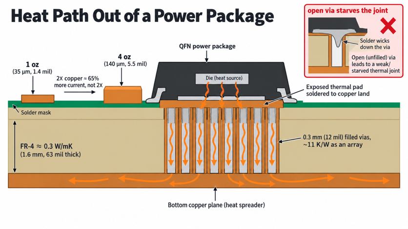
Figure 4: Heavy copper automotive power board with a thermal via array
Thermal vias conduct heat downward through the board rather than sideways. One plated 0.3 mm via through 1.6 mm of FR-4 has a thermal resistance near 170 K/W. An array of sixteen under a power package brings it to roughly 11 K/W, so the array matters far more than any single via. Filling and capping those vias becomes essential once the pad sits under a QFN or DFN. Thermal via design is therefore as much a paste-and-stencil problem as a copper one.
High-Frequency Materials for Radar and Autonomous Sensing
Automotive radar operates in the 76-81 GHz band, and at these frequencies the laminate becomes part of the antenna. FR-4 has a loss tangent near 0.02 and a Dk that drifts with both temperature and glass weave. Both problems worsen with frequency, so FR-4 simply cannot carry a millimeter-wave feed.
- Rogers RO3003 is the usual answer for the antenna layer, with a Dk of 3.00 and a dissipation factor near 0.0010 at 10 GHz. Its ceramic-filled PTFE construction holds Dk steady across the automotive temperature range, so the beam does not wander as the bumper heats up in traffic.
- RO4835 solves the other half of the problem. It is a thermoset hydrocarbon ceramic laminate with a Dk of 3.48, and it is laminated using normal FR-4 processing rather than special PTFE bonding. Its oxidation resistance is what lets a radar module sit behind a bumper for fifteen years.
| Laminate | Dk / Df at 10 GHz | Typical Automotive Use | What This Means for Your Stackup |
|---|---|---|---|
| Standard FR-4 | 4.4 / 0.020 | Body control, lighting, and infotainment | Fine to a few GHz, unusable at 77 GHz |
| High-Tg FR-4, Tg 170 °C | 4.4 / 0.017 | Engine bay ECUs, power modules | Same electricals, far better thermal survival |
| Rogers RO4835 | 3.48 / 0.0037 | Radar feed layers, V2X antennas | Bonds with normal FR-4 processing, hybrid-friendly |
| Rogers RO3003 | 3.00 / 0.0010 | 76 to 81 GHz radar antenna layer | Needs PTFE bonding, keep to the outer layers only |
| Aluminium core | Not applicable | LED headlamps, motor drivers | Single circuit layer, heat exits through the base |
The copper weight determines how much current you can move. The laminate choice decides how much of a 77 GHz signal reaches the antenna.
Rapid Prototyping and SMT Assembly for Smart Vehicles
A production automotive programme runs on frozen processes and PPAP paperwork, but the design inside it was proven on prototypes built in days.
Accelerated Automotive PCB Prototypes for R&D Verification
Automotive PCB prototypes are only useful when built the way production will be. A prototype on standard-Tg FR-4 with 1 oz copper tells you almost nothing about a production board on 170 °C Tg laminate with 2 oz copper. Design verification destroys boards, so a build of five leaves you nothing to work with. Microsectioning a via to measure barrel copper cuts the sample in half, and thermal shock testing runs another until it opens. Budget at least five times the quantity you actually plan to power up.
Lead time matters more in an automotive schedule than it first appears. A validation loop taking three weeks per turn burns a quarter on four iterations, whereas a two-day turn compresses the same work into a month. That gap is usually why a particular supplier gets chosen for the R&D phase.
High-Precision Automotive PCB Assembly and AOI/X-Ray Inspection
Automotive PCB assembly gets judged against IPC-A-610 rather than any house standard
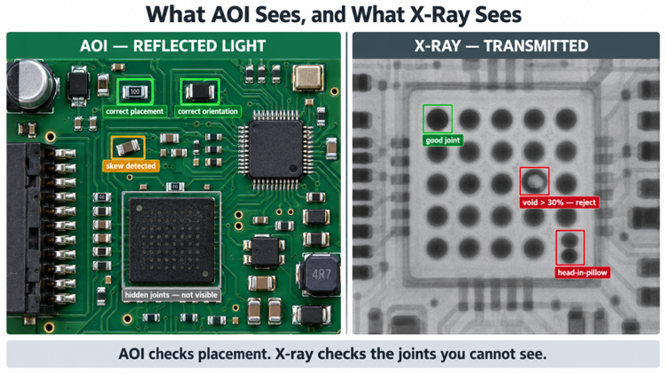
Figure 5: AOI and X-ray inspection of an automotive PCB assembly
Class 3 tightens the acceptance window on everything: fillet size, component skew, and voiding under area array packages. Inspection has to be layered, because no single method sees everything. Automated optical inspection works from reflected light, so it reports only what a camera can see from above. A joint with a package body over it stays invisible, however good the optics are.
- Solder paste inspection measures deposit volume before any part lands, since a large share of assembly defects trace back to the print.
- Pick and place mounts the components, reaching down to 0201 packages on a modern line.
- Reflow follows a profile matched to the laminate, because a 170 °C Tg board wants a longer soak than standard FR-4.
- AOI photographs every board and compares it against the CAD reference, catching missing, skewed, tombstoned, and reversed parts.
- X-ray images the joints that the AOI cannot reach, meaning BGA, QFN, and anything else with a roof over its terminations.
- Functional test powers the assembly and exercises its interfaces, catching faults that survive every visual method.
Head-in-pillow is the defect that makes X-ray non-negotiable on automotive work. The package bows at peak reflow, so corner balls touch the paste without fusing into it. That joint passes a room-temperature continuity test and then opens once the vehicle undergoes vibration and thermal cycling.
JLCPCB's Automotive-Grade PCB Manufacturing Excellence
Automotive requirements once meant a supplier audit, a minimum order, and a quotation by email. That has shifted enough that you can now order boards on automotive-grade laminates from the same quote page you use for a two-layer prototype.
State-of-the-Art Automated Production Lines & IATF 16949 Execution
JLCPCB's manufacturing arm holds a live IATF 16949:2016 certificate, issued by Intertek to Xianjin Electronics (Zhuhai) Co., Ltd. under IATF certificate number 0597398. Its scope reads "Manufacturing of Printed Circuit Boards, Assembly of Printed Circuit Boards," and it runs to February 2029. The certificate sits alongside the ISO documents on the public certifications page.
The production capability behind it covers most automotive board types. Layer counts run to 32, and outer copper reaches 4.5 oz (157 µm, 6.2 mil) on two-layer builds. Minimum trace and space on multilayer is 0.09 mm (3.5 mil). Rogers and PTFE cores, aluminum cores, and Tg 170 °C laminates such as Shengyi S1000-2M are all standard options.
End-to-End Reliability Testing: From Raw Laminates to Turnkey PCBA
Traceability starts well before any copper is etched. The certifications page publishes laminate datasheets and test reports for the materials actually in use. Being able to name the exact laminate is what lets you close out a material declaration. Controlled-impedance boards are TDR-tested on coupons built into the panel border. Standard tolerance is plus or minus 10%, with plus or minus 5% available on request. That matters for automotive Ethernet and for the digital link between a radar front end and its processor.
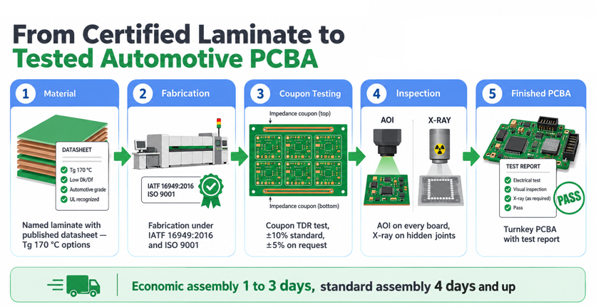
Figure 6: JLCPCB automotive board workflow from certified laminate to tested PCBA
On the assembly side, AOI runs on every board, and X-ray is applied automatically to parts with hidden joints such as BGAs. Standard PCBA places components down to 0201 with BGA pitches to 0.35 mm (14 mil), while the economic tier stops at 0402 and 0.5 mm (20 mil). Choosing between the tiers is really a decision about your smallest package.
FAQs about Automotive PCB
Q: Is there such a thing as an IATF 16949-certified PCB?
No, because IATF 16949 certifies a manufacturing site's quality management system rather than any individual product. A supplier can be certified, and your board can be built under that system, but the board itself never carries the certificate.
Q: Can I use a standard commercial capacitor instead of an AEC-Q200 part?
For bench prototypes, usually yes. For anything going into a vehicle, no, because the commercial part was never stress tested for the temperature cycling, humidity, and vibration a car delivers.
Q: Does an automotive PCB always have to be IPC Class 3?
Most automotive boards are built to Class 2 with selected Class 3 requirements, or to IPC-6012DA, the automotive addendum. Full Class 3 is reserved for safety-critical functions such as braking, steering, and airbag control.
Q: Can FR-4 be used for a 77 GHz radar board?
Not for the antenna and feed layers, since a loss tangent near 0.02 and a weave-dependent Dk destroy the beam pattern at millimeter-wave frequencies. FR-4 works well for the power and digital layers underneath, which is why most radar modules are hybrid stackups with a thin Rogers layer on top.
Q: My board passed every electrical test and failed months later in the vehicle. What happened?
The two usual suspects are plated barrel fatigue and head-in-pillow solder joints. Both produce connections that measure fine at room temperature and then open under thermal cycling or vibration. Microsectioning a via and X-raying the area array packages will normally tell you which one you have.
Conclusion
Automotive PCB work is less about exotic technology than about proving ordinary technology will still function in fifteen years. Every requirement here traces back to that single goal. IATF 16949 ensures process repeatability, and AEC-Q200 screens the passives. IPC Class 3 puts extra copper where fatigue attacks, while high-Tg laminate keeps the resin stiff throughout.
What has genuinely changed is that these capabilities are no longer gated behind a minimum order. Automotive laminates, heavy copper, controlled impedance, and X-ray inspection are all reachable at prototype quantities. A small team can therefore validate against production conditions from the first turn. Start your next design on the material and the class you intend to ship, and qualification stops being a rediscovery exercise. Published certificates and short prototype lead times are what make running that loop properly affordable.

Keep Learning
QFN Package: Structure, PCB Design, and Assembly
Key Takeaways Choose the correct PCB footprint: Follow the QFN manufacturer’s recommended land pattern and package datasheet. Optimize thermal management: Use appropriate thermal pads and thermal vias to improve heat transfer. Control solder paste application: Design stencil apertures to achieve suitable solder volume and reduce assembly defects. Inspect hidden solder joints: Use X-ray inspection when required by the product’s reliability needs and inspection plan. Design for manufacturability (DFM): ......
Navigating Automotive PCB Manufacturing Standards and High-Reliability Fabrication
Key Takeaways Harsh Operating Environments: Engineered to survive 15 years under thermal cycling (-40 °C to 150 °C) and severe vibration. Strict Compliance: Guided by IATF 16949, AEC-Q200 components, and IPC Class 3 standards. Targeted Materials: Leverages high-Tg/heavy copper for power and Rogers substrates for 77 GHz radar. Zero-Defect Inspection: Employs 3D AOI and X-ray testing to eliminate hidden solder joints failures. An automotive PCB has to keep working for fifteen years in the same place. Bo......
Battery PCB Board: What You Need to Know
Key Takeaways Battery PCB boards support power distribution, protection, monitoring, and cell balancing. PCB types include single-layer, multilayer, flexible, and HDI designs. Current capacity, thermal management, and routing density are key design considerations. Reliable manufacturing depends on proper materials, fabrication, assembly, and testing. Battery PCB boards are used in a wide range of battery-powered electronics, from smartphones and laptops to electric vehicles and energy storage systems.......
Medical PCB Manufacturing: Key Standards, Types, and High-Reliability Fabrication
Key Takeaways Strict Compliance: Demands ISO 13485 QMS certification, IPC Class 3 specs (25 µm copper barrels), and IEC 60601-1 safety rules. Targeted Substrates: High-Tg FR-4 handles autoclave heat, polyimide flex serves wearables, and metal/ceramic cores manage high power. Quality & Traceability: Layered AOI, X-ray inspection, and full IPC-1782 lot tracking prevent critical field failures. A medical PCB carries a level of responsibility that consumer electronics rarely face, because a patient’s diag......
A Complete Guide to Package Substrates: Materials, Structure, Types, and PCB Differences
Key Takeaways Definition: A package substrate is the fine-pitch organic carrier connecting a bare die to the system board. Not a PCB: Substrates are routed several times finer than advanced HDI and use entirely different dielectrics. Materials: BT resin cores carry wire-bond and CSP work, while glass-free ABF build-up film carries flip chip. Process: Semi-additive plating, not etching, is what makes single-digit micrometer lines possible. Constraint: Substrate capacity, not wafer supply, now limits hi......
Comprehensive Guide to QFN Packages: Advantages, Types, and Applications in Electronics
Key Takeaways Thermal Vias: Place 0.3mm vias in the exposed pad to draw heat away from the IC. Voiding Control: Apply a window-pane stencil (50–75% coverage) to prevent solder voids. Prevent Wicking: Use tented vias or Via-in-Pad to stop solder from leaking. Hidden Joints: Require X-ray inspection (AXI) since QFN leads are under the package. JLCPCB SMT: Fully supports 0.4mm pitch QFNs, Via-in-Pad, and AXI quality checks. Quad flat no-lead (QFN) packages are a type of IC package that are small, lightwe......