Medical PCB Manufacturing: Key Standards, Types, and High-Reliability Fabrication
15 min
- Critical Demands of Modern Medical PCB Applications
- Key Types of Medical PCBs and Material Selection
- Manufacturing and Quality Standards for Medical Electronics
- Rapid Medical PCB Prototypes and Turnkey Assembly
- JLCPCB's Medical-Grade PCB Fabrication & Assembly Capabilities
- FAQs about Medical PCB
- Conclusion
Key Takeaways
- Strict Compliance: Demands ISO 13485 QMS certification, IPC Class 3 specs (25 µm copper barrels), and IEC 60601-1 safety rules.
- Targeted Substrates: High-Tg FR-4 handles autoclave heat, polyimide flex serves wearables, and metal/ceramic cores manage high power.
- Quality & Traceability: Layered AOI, X-ray inspection, and full IPC-1782 lot tracking prevent critical field failures.
A medical PCB carries a level of responsibility that consumer electronics rarely face, because a patient’s diagnosis, treatment, or heartbeat may depend on it working exactly as intended. An infusion pump cannot tolerate an unreliable production batch, and a defibrillator cannot simply be rebooted in the middle of use.
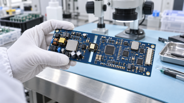
Figure 1: A multilayer patient monitor PCB under inspection
Regulatory responsibility belongs to the company that places the finished medical device on the market. What a qualified fabricator can provide is something equally important: a controlled, documented, and repeatable manufacturing process. This guide explains where medical PCBs are used and which substrate materials are suited to demanding medical environments.
Critical Demands of Modern Medical PCB Applications
Medical electronics splits into two worlds that have almost no overlap in requirements. One is a 200 kg imaging scanner in a shielded room, while the other is a sensor patch worn on the chest for a week.
Diagnostic, Imaging, and Portable Device Innovations
Imaging systems push the board on channel count rather than on raw speed. An ultrasound beamformer handles 64 to 256 receive channels at once, so the front end fans out into 12 to 20 layers. Every lane needs matched impedance, because a reflection on a receive channel shows up as an artifact in the image.
The analog front end usually dictates the layout because multiple ECG or EEG channels into one 24-bit converter. It resolves signals in the microvolt range, where noise from a nearby power or digital plane can quickly erase useful resolution. That is why the analog section needs its own quiet reference copper.
| Device Class | Typical Board | Dominant Requirement | What This Means for Your Stackup |
|---|---|---|---|
| Imaging: CT, MRI, ultrasound | 12 to 20-layer rigid | Channel count and low-loss routing | Controlled impedance on every detector lane, low-Df laminate |
| Patient monitoring: ECG, SpO2 | 4 to 8-layer rigid | Microvolt analog integrity | Guarded analog island with its own uninterrupted reference plane |
| Infusion pumps and ventilators | 4 to 6-layer rigid, mains-fed | Patient isolation | 8 mm (315 mil) creepage across the barrier, keep-out on both sides |
| Wearables and skin patches | 1 to 4-layer polyimide flex | Bend life and total thickness | Rolled annealed copper, coverlay instead of solder mask |
| Endoscopes and catheters | Fine-line flex or rigid-flex | Width under a few millimeters | 0.076 mm (3 mil) traces, stiffener only where connectors land |
The Zero-Failure Mandate for Life-Critical Electronics
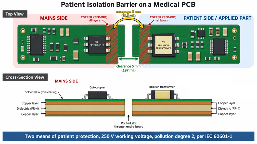
Figure 2: Board-level isolation barrier showing the milled slot, creepage path, and keep-out zones
- Isolation and patient safety: IEC 60601-1 defines the required protection barriers. Devices with applied parts often require two Means of Patient Protection (MOPP).
- Creepage and clearance: At 250 V working voltage and Pollution Degree 2, two MOPP commonly require about 8 mm creepage and 5 mm clearance.
- Isolation slots: Milling a slot beneath the isolator increases creepage and provides a stronger isolation barrier than copper spacing alone.
- Do not rely on solder mask: Solder mask is a coating, not a dependable insulation barrier, so isolation spacing should be designed as if it were absent.
- Sterilization matters: Autoclave cycles typically operate at 121–134 °C, and reusable medical equipment may experience hundreds of cycles.
- Choose laminate Tg carefully: Standard FR-4 with a Tg near 130 °C can approach its softening region during sterilization. Selecting the Tg of your laminate, therefore becomes a reliability and safety decision.
- Risk management: ISO 14971 requires manufacturers to identify possible failures, assess their harm, and document how the design controls each risk.
- Documented failure controls: A cracked via barrel should be treated as an identified hazard with defined mitigation, not simply as an unexplained field failure.
Key Types of Medical PCBs and Material Selection
Medical work spans a wider range of board construction than almost any other sector. The same hospital room holds a 20-layer imaging board and a flex circuit thinner than a business card, so no single process covers both.
High-Layer Rigid Boards for Complex Medical Systems
High layer counts in medical systems stem more from routing pressure than from clock speed. A CT detector module carries hundreds of low-level channels away from the sensor. Those channels must not couple, so signal layers get sandwiched between grounds. Twelve to twenty layers are normal, and each added pair means another lamination cycle to survive. Density then drives HDI construction, in which laser-drilled microvias replace mechanically drilled ones.
An HDI stackup is not free because each microvia layer requires its own lamination and laser-drilling pass. What the cost buys back is layer count, so the board fits inside a handheld housing. The guide to HDI PCBs works through that arithmetic.
Substrates for Superior Thermal Stability and Signal Integrity
Substrate choice in medical work is determined more by the environment than by the circuit. A console board has different needs from one that's autoclaved twice a day, so start with the cleaning protocol rather than the schematic.
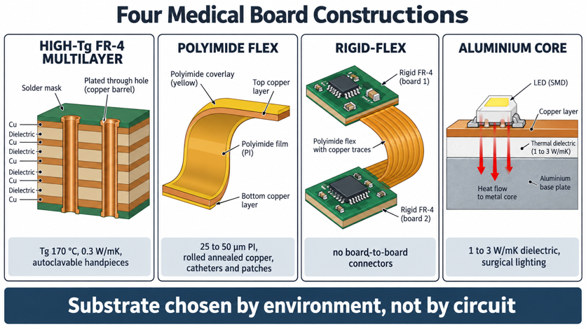
Figure 3: Cross-sections of the four medical board constructions side by side
| Substrate | Key Property | Thermal Conductivity | Where It Belongs in a Medical Device |
|---|---|---|---|
| Standard FR-4, Tg 130 to 140 °C | Dk about 4.5 | 0.3 W/mK | Console electronics that never get sterilized |
| High-Tg FR-4, Tg 170 °C | Lower z-axis expansion | 0.3 W/mK | Autoclaved handpieces and any board past 8 layers |
| Polyimide flex | Stable well past 300 °C, Dk 3.2 to 3.5 | 0.2 W/mK | Wearable patches, endoscope tips, cand atheter interconnect |
| Rogers RO4350B | Dk 3.48, Df 0.0037 | 0.69 W/mK | MRI coil and ultrasound RF front ends |
| Aluminium core | Metal base under a thermal dielectric | 1 to 3 W/mK in the dielectric | Surgical lighting, laser drivers, therapy power stages |
| Alumina ceramic | CTE close to silicon | 24 to 30 W/mK | Implantable modules and bare-die hybrids |
FR-4 moves heat at roughly 0.3 W/mK, which is fine until a part dissipates real power. A surgical LED array cooks itself on plain FR-4, while the same array on an aluminum core runs cool.
Polyimide earns its place in mechanics rather than on heat. It holds its properties past 300 °C, and it bends without cracking, so a catheter interconnect can be threaded through a vessel. Flex boards use rolled annealed copper because that grain structure survives repeated bending. The polyimide flex material guide covers the choices for coverlay and stiffener.
Manufacturing and Quality Standards for Medical Electronics
Two separate systems govern a medical board, and confusing them wastes months. One certifies how the factory runs, while the other sets the physical acceptance criteria for the copper.
ISO 13485 Certification and IPC Class 3 Fabrication Rules
ISO 13485:2016 certifies a quality management system, not a product. The certificate says the fabricator controls documents, validates processes, and keeps auditable records. It does not say your board is approved, because approval goes to a device from a regulator rather than to a bare PCB from a certification body.
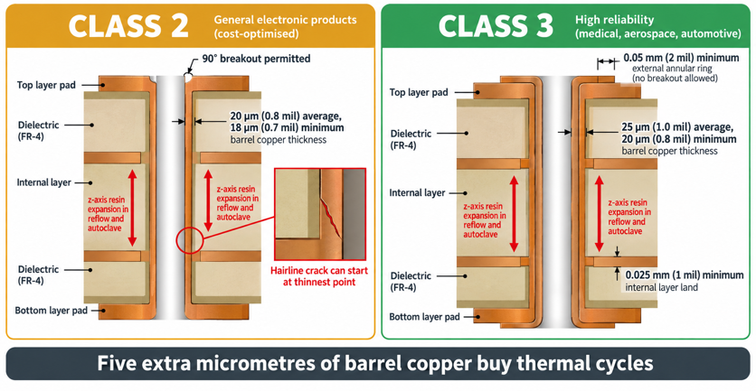
Figure 4: IPC Class 2 versus Class 3 acceptance criteria on a plated through-hole
IPC Class 3 is the physical half of the answer. It is the highest of three acceptance classes in IPC-6012 and IPC-A-610, and it exists where downtime cannot be tolerated. The differences look small in micrometers and large in service life.
| Fabrication Attribute | IPC Class 2 | IPC Class 3 | Why the Tighter Number Matters |
|---|---|---|---|
| Average copper in the plated barrel | 20 µm (0.8 mil) | 25 µm (1.0 mil) | A thicker wall survives more thermal cycles before it cracks |
| Minimum copper at any point in the barrel | 18 µm (0.7 mil) | 20 µm (0.8 mil) | Removes the thin spot where a barrel always fails first |
| External annular ring | 90-degree breakout allowed | 0.05 mm (2 mil) minimum, no breakout | Keeps full pad support under a via that gets flexed or shocked |
| Internal annular ring | Breakout permitted | 0.025 mm (1 mil) minimum | Guarantees a complete copper connection on every inner layer |
Those five extra micrometers of barrel copper are the most valuable line in the table. Resin expands in the z-axis several times faster than copper, so every reflow and every autoclave cycle stretches the barrel. The plated copper thickness you specify decides how many stretches it survives.
Traceability and Material Cleanliness Requirements
Traceability answers one question a regulator will eventually ask. Which other units share the problem you just found? IPC-1782B is the industry standard for it, and it scales the required depth to product risk. For a life-supporting device, that usually means tracing each assembly to a laminate lot, a paste lot and a build date. Making that work starts on your fabrication drawing rather than in the factory. Every panel needs a unique identifier in silkscreen or laser marking, and it has to survive depaneling and coating. Leave the marking off, and the fab will place it wherever there is room, so it often ends up under a component.
The classic screen is the ROSE test in IPC-TM-650 method 2.3.25. It historically capped ionic contamination at 1.56 µg of sodium chloride equivalent per square centimeter. That figure is no longer the whole answer, because revision H of IPC J-STD-001 moved to objective evidence instead.
A ROSE reading tells you that something ionic is present. Ion chromatography tells you what it is, so you can fix the source instead of rewashing.
Rapid Medical PCB Prototypes and Turnkey Assembly
Clinical programs run on frozen designs and lengthy documentation cycles, yet the design within them is proven on prototypes built in days.
Accelerating Medical PCB Prototypes for Clinical Verification
Medical PCB prototypes are only useful when they are built the way they will be in production. A prototype on standard-Tg FR-4 tells you little about a production board on 170 °C Tg laminate. The two behave differently during reflow and in the autoclave, so any thermal data must be collected a second time.
Verification consumes boards rather than accumulating them. Microsectioning a via to measure barrel copper destroys the sample, and a thermal shock sequence takes another one to failure by design. Order at least five times the quantity you actually plan to power up. Iteration speed compounds over the course of a clinical program. A three-week fabrication turn burns most of a quarter across four revisions, while a two-day turn compresses the same four loops into a month. That difference is usually why a particular fabricator gets picked for verification work.
Precision Medical PCB Assembly with Advanced Inspection (AOI & X-Ray)
Medical PCB assembly is judged against IPC-A-610 rather than against any house standard. Class 3 narrows the acceptance window on fillet size, component skew, and voiding under area array packages. Inspection has to be layered, because no single method sees every defect. The sequence below is what a controlled medical line runs, and each step catches something the previous one could not.
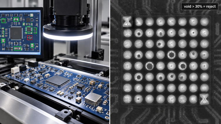
Figure 5: AOI and X-ray inspection of a medical PCB assembly
- Solder paste inspection measures deposit volume before any component lands, since a large share of assembly defects trace straight back to the print.
- Pick and place mounts the parts, reaching down to 0201 packages on a modern line.
- Reflow follows a profile matched to the laminate, because a 170 °C Tg board wants a longer soak than standard FR-4.
- AOI photographs every board and compares it against the CAD reference, catching missing, skewed, tombstoned, and reversed parts.
- X-ray images the joints AOI cannot reach, which means BGA, QFN, and anything else with a package body over its terminations.
- Functional test powers the assembly and exercises its interfaces, catching faults that survive every visual method.
AOI works from reflected light, so it reports only what a camera can see from above. That limit is why X-ray is not optional on a medical board carrying a BGA. Head-in-pillow proves the point, because the package bows at peak reflow and the corner balls touch the paste without fusing. The joint passes a continuity check and then opens under vibration.
JLCPCB's Medical-Grade PCB Fabrication & Assembly Capabilities
Medical-grade fabrication once meant a supplier audit, a minimum order, and a quotation by email.
Cleanroom Manufacturing and Certified Quality Management Systems
JLCPCB's manufacturing arm holds a live ISO 13485:2016 certificate for medical device quality management. It sits beside ISO 9001:2015, ISO 14001:201,5 and an IATF 16949:2016 certificate on the public certifications page. Intertek issued the IATF certificate under number 0597398, and its scope reads "Manufacturing of Printed Circuit Boards, Assembly of Printed Circuit Boar."".
Environmental control is real here, but it is worth stating precisely. JLCPCB's own factory walkthrough describes specialized clean rooms with controlled airflow, used to keep the imaging and lamination stages particle-free. A single particle at those steps becomes an etched-in open circuit. What the company does not publish is an ISO 14644 cleanliness class for those areas.
End-to-End Turnkey Solutions from Prototype to Mass Production
Fabrication capability covers most medical board types, except implantables. Rigid builds run from 1 to 32 layers, with a minimum trace and space of 0.09 mm (3.5 mil) on multilayer. Minimum drilled hole size is 0.15 mm (6 mil), so many fine-pitch escapes are possible without paying for HDI.
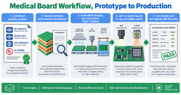
Figure 6: The JLCPCB medical board workflow
Controlled impedance is available on 4 layers and above. Standard tolerance is ±10 %, with ±5 % on request. Detector links and radio front ends are usually the only medical circuits that need the tighter band, so do not buy it elsewhere.
Flexible construction runs 1 to 4 layers on 25- or 50-µm polyimide, with rolled, annealed copper from 12 to 35 µm. Minimum trace and space reaches 0.076 mm (3 mil) on 12 µm copper, which is what a catheter interconnect needs. ENIG is the standard finish there, because fine-pitch placement depends on a flat, oxidation-resistant surface.
FAQs about Medical PCB
Q: Does an ISO 13485 certified PCB manufacturer make my board FDA approved?
No. ISO 13485:2016 certifies the manufacturer's quality management system, while approval or clearance is granted to a finished device by a regulator. The certificate is evidence you cite inside your own technical file, alongside your ISO 14971 risk analysis and IEC 60601-1 testing.
Q: Do I need IPC Class 3 for the whole medical board?
Usually not, because applying it everywhere inflates every pad and can cost you a routing layer. Scope Class 3 to the nets, vias, and joints carrying safety-relevant functions, and let the rest sit at Class 2. Document the reasoning so an auditor can follow it.
Q: Can a standard PCB fabricator build boards for an implantable device?
Generally, no, since implantable work usually involves bare die attach, gold wire bonding or hermetic packaging inside a classified cleanroom. Those processes belongtoh a specialist microelectronics house. A mainstream fabricator suits the external electronics, such as programmers, chargers, and monitors.
Q: Which laminate should I choose for an instrument that gets autoclaved?
Choose a high-Tg FR-4 rated around 170 °C rather than standard 130 to 140 °C material. Steam autoclave cycles run at 121 to 134 °C, so a low-Tg laminate sits near its glass transition every cycle. The repeated z-axis expansion then works the via barrels loose over time.
Q: How much creepage do I need across a patient isolation barrier?
For two means of patient protection at 250 V in pollution degree 2, IEC 60601-1 typically calls for 8 mm creepage and 5 mm clearance. Mill a slot under the isolator, because air plus a routed gap gives creepage that the solder mask cannot.
Conclusion
A medical PCB is not made reliable by one clever decision. It is made reliable by a chain of ordinary ones that were each written down. The laminate that survives the autoclave, the barrel copper that withstands thermal cycles, the slot that keeps the mains away from the patient, and the lot record that identifies every affected unit. Read the standards in that order and they stop competing for your attention. ISO 13485 governs how the factory behaves, IPC Class 3 governs what the copper must measure, and IEC 60601-1 governs what the patient touches.
None of them approves your device because that decision belongs to a regulator who reviews the file you build. Devices keep shrinking as wearables and single-use instruments take work away from hospital consoles. That trend pushes more medical boards toward flex, HDI, and tighter acceptance criteria every year. Start from a certified process and a fabricator that hands you real material and lot of data, so the next transition stays a documentation exercise.

Keep Learning
Navigating Automotive PCB Manufacturing Standards and High-Reliability Fabrication
Key Takeaways Harsh Operating Environments: Engineered to survive 15 years under thermal cycling (-40 °C to 150 °C) and severe vibration. Strict Compliance: Guided by IATF 16949, AEC-Q200 components, and IPC Class 3 standards. Targeted Materials: Leverages high-Tg/heavy copper for power and Rogers substrates for 77 GHz radar. Zero-Defect Inspection: Employs 3D AOI and X-ray testing to eliminate hidden solder joints failures. An automotive PCB has to keep working for fifteen years in the same place. Bo......
Battery PCB Board: What You Need to Know
Key Takeaways Battery PCB boards support power distribution, protection, monitoring, and cell balancing. PCB types include single-layer, multilayer, flexible, and HDI designs. Current capacity, thermal management, and routing density are key design considerations. Reliable manufacturing depends on proper materials, fabrication, assembly, and testing. Battery PCB boards are used in a wide range of battery-powered electronics, from smartphones and laptops to electric vehicles and energy storage systems.......
Medical PCB Manufacturing: Key Standards, Types, and High-Reliability Fabrication
Key Takeaways Strict Compliance: Demands ISO 13485 QMS certification, IPC Class 3 specs (25 µm copper barrels), and IEC 60601-1 safety rules. Targeted Substrates: High-Tg FR-4 handles autoclave heat, polyimide flex serves wearables, and metal/ceramic cores manage high power. Quality & Traceability: Layered AOI, X-ray inspection, and full IPC-1782 lot tracking prevent critical field failures. A medical PCB carries a level of responsibility that consumer electronics rarely face, because a patient’s diag......
A Complete Guide to Package Substrates: Materials, Structure, Types, and PCB Differences
Key Takeaways Definition: A package substrate is the fine-pitch organic carrier connecting a bare die to the system board. Not a PCB: Substrates are routed several times finer than advanced HDI and use entirely different dielectrics. Materials: BT resin cores carry wire-bond and CSP work, while glass-free ABF build-up film carries flip chip. Process: Semi-additive plating, not etching, is what makes single-digit micrometer lines possible. Constraint: Substrate capacity, not wafer supply, now limits hi......
Comprehensive Guide to QFN Packages: Advantages, Types, and Applications in Electronics
Key Takeaways Thermal Vias: Place 0.3mm vias in the exposed pad to draw heat away from the IC. Voiding Control: Apply a window-pane stencil (50–75% coverage) to prevent solder voids. Prevent Wicking: Use tented vias or Via-in-Pad to stop solder from leaking. Hidden Joints: Require X-ray inspection (AXI) since QFN leads are under the package. JLCPCB SMT: Fully supports 0.4mm pitch QFNs, Via-in-Pad, and AXI quality checks. Quad flat no-lead (QFN) packages are a type of IC package that are small, lightwe......
Unlocking Smaller and Smarter PCBs with Embedded Components
Have you ever opened a smartwatch or a pair of wireless earbuds, looked at the miniature chip inside, and wondered how engineers could pack so much functionality into such a small enclosure? While surface-mount technology (SMT) has become incredibly sophisticated—with the advent of ultra-small 0201 and 01005 packages—there is a physical limit to how many components can be crammed onto the surface of a board. To bypass this bottleneck, the electronics manufacturing industry is increasingly turning to e......