What Is a Thermoelectric Generator and How Does It Work?
15 min
- What Is a Thermoelectric Generator?
- How Do Thermoelectric Generators Work?
- What Is Inside a Thermoelectric Generator?
- What Determines Thermoelectric Generator Performance?
- How Much Power Can a Thermoelectric Generator Produce?
- What Are Thermoelectric Generators Used For?
- Thermoelectric Generators vs. Thermoelectric Coolers
- Advantages and Limitations of Thermoelectric Generators
- FAQs About Thermoelectric Generator
Can heat from an engine, industrial process, or other heat source be turned into useful electricity without moving parts? A thermoelectric generator (TEG) does this by converting a temperature difference directly into electrical power through the Seebeck effect. Its power output depends on the temperature difference across the device, the thermoelectric materials, and the overall system design.
What Is a Thermoelectric Generator?
A thermoelectric generator (TEG) is a solid-state device that converts heat into electricity when its hot and cold sides are maintained at different temperatures. Through the Seebeck effect, this temperature difference produces a voltage that can drive current through an external circuit.
A heat source alone is not enough. The cold side must remain cooler than the hot side to sustain the temperature difference. As the two sides approach the same temperature, the generated voltage decreases.
Unlike conventional generators, which typically use mechanical motion and electromagnetic induction to generate electricity, TEGs have no moving mechanical parts. This makes them useful in applications where compact size, silent operation, and low maintenance are priorities, particularly when recovering waste heat. However, their power output is generally modest, making conventional generators more suitable for many high-power applications.
How Do Thermoelectric Generators Work?
The Seebeck Effect
Engines, furnaces, processors, cooling systems, and human bodies all reject heat. That sounds like a broad energy resource, yet a thermoelectric generator cannot run on temperature alone. It needs a temperature difference across the material. If both ends become equally warm, the voltage disappears even though the entire device still contains thermal energy.
When a thermoelectric material spans hot and cold regions, charge carriers redistribute in response to the temperature gradient. The resulting voltage per unit temperature difference is the Seebeck coefficient, S, usually reported in microvolts per kelvin. A larger magnitude means more open-circuit voltage for the same gradient.
How P-Type and N-Type Semiconductors Work
The sign of the Seebeck coefficient identifies the dominant carrier behavior: p-type materials have a positive coefficient, while n-type materials have a negative one. Because the two carrier types respond to a gradient in opposite ways, a p-type leg and an n-type leg spanning the same temperature difference drive current around the module in the same direction, which is why conventional modules pair them.
Flexible n-type organic materials can lose their thermoelectric properties when exposed to air. A 2019 Advanced Electronic Materials study, summarized in a 2022 review of graphene and MXene coatings, examined a carbon nanotube, polyethyleneimine, and graphene-oxide multilayer. Processing and a protective coating improved its electrical properties and air stability.
In a flexible device, material treatment and protection must suit the substrate. A process that works on PET may need to change for a heat-sensitive fabric.
From a Temperature Difference to Electrical Power
Open-circuit voltage is not the same as usable power. Once a load is connected, current must pass through the thermoelectric coating, contacts, interconnects, and load. High internal resistance can turn an impressive Seebeck voltage into negligible current. The power factor, electrical conductivity multiplied by S squared, captures two of these material terms, but it still omits heat leakage.
The dimensionless figure of merit zT combines electrical conductivity, Seebeck coefficient, absolute temperature, and thermal conductivity: zT = σS²T/k. A useful thermoelectric should conduct charge well, generate substantial voltage per kelvin, and conduct heat poorly enough to preserve the gradient. These wishes conflict because the same carriers and structures that move electrical charge can also move heat.
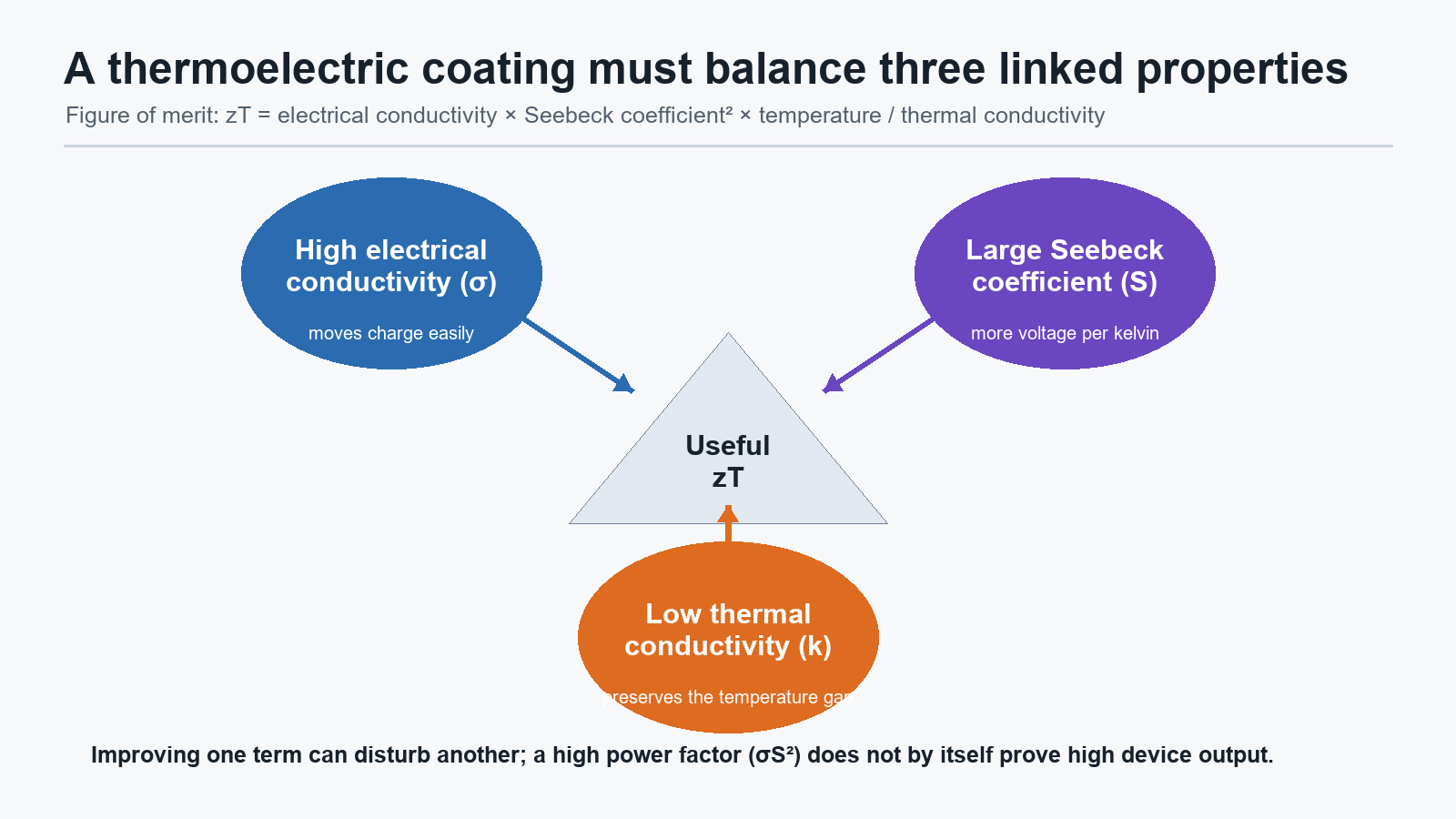
Thermoelectric performance depends on high electrical conductivity and Seebeck coefficient together with low thermal conductivity. Improving one property can disturb another.
What Is Inside a Thermoelectric Generator?
The familiar thermoelectric module alternates p-type and n-type legs. Each pair shares the same hot and cold sides, so the legs are thermally parallel. Electrical interconnects place them in series so their voltages add. A single coating can show a strong Seebeck coefficient, but a generator requires complementary carrier types, repeatable patterning, low-resistance connections, and a layout that maintains the gradient across every leg.
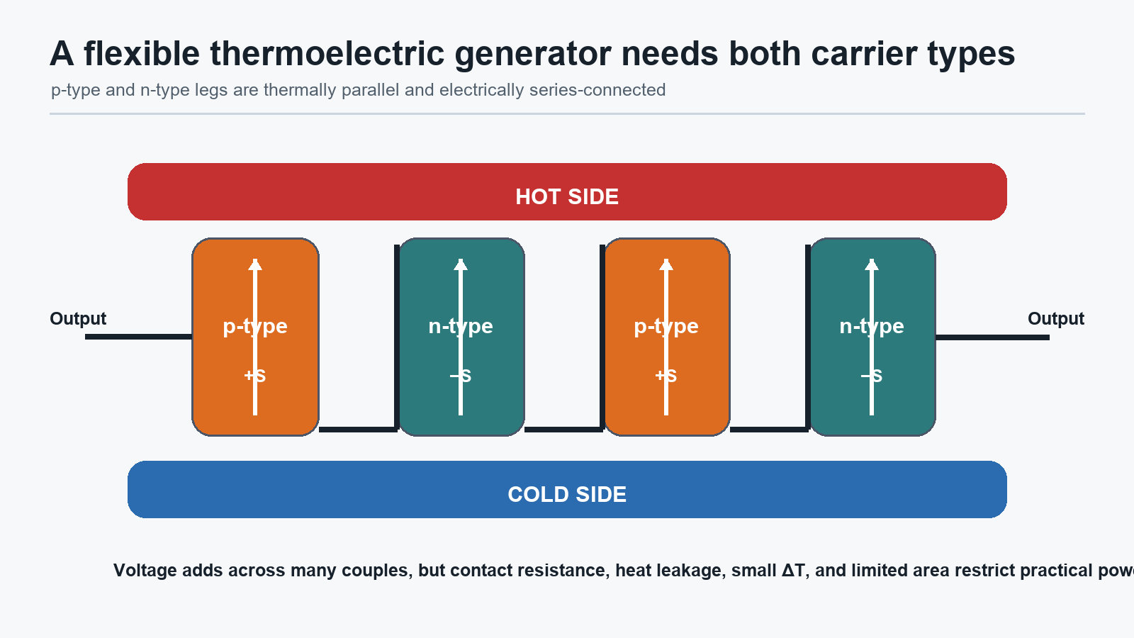
A thermoelectric generator needs both carrier types: p-type and n-type legs are thermally parallel and electrically series-connected. Voltage adds across many couples, but contact resistance, heat leakage, a small ΔT, and limited area restrict practical power.
In flexible generators, the thermoelectric function is often built as a coating rather than a freestanding pellet. A coating can put a connected network on PET, paper, cotton, or another lightweight surface using dip, spray, or layer-by-layer deposition. Two-dimensional flakes provide broad conductive pathways; one-dimensional nanotubes can bridge gaps; conductive polymers can stabilize dispersions and adjust carrier behavior. Repeated coating cycles tune thickness and composition without requiring a freestanding brittle pellet.
Because the electrical result depends on the full ink-substrate-process system, matching 2D conductive inks to coating processes is part of thermoelectric design rather than a separate manufacturing detail.
As an example of what a coated leg can contain, a 2016 Advanced Energy Materials study, also covered in the same review, reported a roughly 1 µm p-type multilayer on PET containing polyaniline, graphene nanoplatelets, carbon nanotubes, and PEDOT:PSS. It reached about 1.9 × 10^5 S m−1 electrical conductivity and about 120 µV K−1 Seebeck coefficient, corresponding to a power factor of 2710 µW m−1 K−2. These material figures demonstrate a favorable combination under the study conditions; they do not by themselves establish full-generator efficiency or wearable output.
What Determines Thermoelectric Generator Performance?
Temperature Difference
Everything starts with the temperature difference across the thermoelectric legs, not the absolute temperature of the device. The distinction is crucial for flexible devices. A conformal coating may make excellent contact with a curved hot surface, but the opposite side must remain cooler. On machinery, a strong heat source may be available, but the cold-side design, insulation, and attachment become part of the generator.
Because open-circuit voltage is the Seebeck coefficient multiplied by the temperature difference, a larger maintained gradient directly raises the voltage available from the same legs.
Thermoelectric Materials
Commercial thermoelectric modules commonly use bismuth telluride (Bi₂Te₃) based materials near room temperature. Lead telluride and silicon-germanium are used at higher temperatures, including in radioisotope generators on space missions. These rigid inorganic semiconductors can offer high conversion performance, but may carry cost, processing, or availability concerns and do not naturally follow textiles or moving surfaces. Conductive coatings based on graphene-related materials, carbon nanotubes, polymers, and potentially MXenes offer another route: build the electrical function as a thin network on a compliant substrate. The route improves form factor, not automatically conversion efficiency.
The network must be more than conductive. If adding graphene raises conductivity but lowers the Seebeck coefficient, the power factor may improve, worsen, or pass through an optimum. If a thick film carries current well but also spreads heat along the substrate, the actual temperature drop across each thermoelectric leg can shrink. Binders improve adhesion yet may interrupt electronic paths. Annealing can raise conductivity while exceeding the thermal tolerance of a textile or low-cost polymer.
Heat Transfer and Thermal Management
A through-plane generator places the hot and cold surfaces on opposite faces. This can create a direct heat path but is difficult to realize with very thin coatings because the thickness available for a temperature drop is small. An in-plane generator patterns long p-type and n-type elements across a surface so hot and cold zones lie apart laterally. It suits printed or coated textiles, though the substrate itself can conduct heat between zones.
Long, narrow legs can support a temperature difference but raise electrical resistance. Short, wide legs reduce resistance but can leak more heat. Adding more couples raises voltage, yet also adds interconnects and contact losses. A flexible layout must survive bending without breaking those junctions or changing contact pressure at the heat source. The optimal geometry therefore depends on the available area, gradient direction, load resistance, and allowable thickness.
Encapsulation presents another trade-off. A barrier can protect an air-sensitive n-type layer or prevent abrasion, but it can add stiffness and thermal resistance. On the hot side, thermal resistance can prevent heat from entering the leg; on the cold side, it can slow heat rejection. Protection must be designed as part of the heat path, not added after electrical optimization.
Electrical Load
The connected load also decides how much of that voltage becomes usable power. A generator has internal resistance — from the thermoelectric legs themselves, the contacts, and the interconnects — so delivered power peaks only when the load is matched to the device impedance. This is why quoting open-circuit voltage alone describes the wrong operating point: matched-load, maximum-power conditions are the numbers that matter.
Internal resistance is not constant, either. Bending, washing, and aging can shift impedance enough to reduce maximum power or upset load matching, even while the device still generates voltage. A generator therefore has to be characterized with the load it will actually drive.
How Much Power Can a Thermoelectric Generator Produce?
Material power factor is useful for screening, but device evaluation needs a maintained temperature difference, module area and thickness, internal resistance, load, and thermal boundary conditions. Open-circuit voltage should be paired with current-voltage and power curves. Measurements should identify whether the quoted temperature difference is across the thermoelectric legs or merely between distant hot and cold plates.
A 2020 Advanced Functional Materials study, described in the same review, illustrates the scale of the challenge. The researchers connected spray-coated p-type and n-type cotton elements as two p/n thermocouples. At a temperature difference of about 70 K, the device produced about 1.65 mV and a maximum power of about 1.0 nW. The experiment demonstrates generation in a flexible textile, but its large imposed gradient is not representative of every body-heat setting, and the power is far below what most standalone electronics require.
When evaluating a reported thermoelectric generator, define the full measurement context:
- Define the heat source, cold-side cooling, contact pressure, ambient conditions, and actual ΔT across the active material.
- Report p- and n-type properties, leg dimensions, number of couples, contact resistance, and encapsulation.
- Match the electrical load and describe maximum-power conditions rather than quoting voltage alone.
- Track thermoelectric and electrical performance after realistic bending, washing, and air exposure.
What Are Thermoelectric Generators Used For?
TEG applications follow the principle directly: wherever a maintained temperature difference exists and modest, highly reliable power is enough, a thermoelectric generator is a candidate.
Waste Heat Recovery
Engines, furnaces, processors, and cooling systems all reject heat continuously. A thermoelectric generator placed across that rejected heat flow converts part of it into electricity without consuming additional fuel. The recovered contribution is small, so flexible 2D coatings are most valuable where a small, distributed energy contribution is useful or where rigid modules cannot maintain contact.
Wearable and Body-Heat Applications
Devices built from 2D and carbon-based conductive coatings can conform to skin, textiles, and curved equipment, making them candidates for body-heat harvesting. On skin, clothing and ambient air may offer only a modest gradient, and movement continually changes contact and cooling. Body heat can generate voltage when the device maintains a temperature difference between skin and ambient air, but whether that small gradient survives daily clothing and motion is what ultimately limits wearable output.
Remote Sensors and IoT Devices
A small, continuous harvested current pairs naturally with devices that spend most of their time asleep. For duty-cycled sensor nodes and IoT devices, the generator replenishes a storage stage between measurements, and the node spends that energy in short bursts. Flexible TEGs are therefore more realistic for low-power sensing or charging an energy-storage stage than for continuously powering general-purpose electronics.
Automotive Applications
Vehicle engines reject heat continuously, which makes automotive exhaust streams a recurring candidate for thermoelectric heat recovery. Exhaust surfaces can reach several hundred degrees Celsius, so automotive prototypes use rigid inorganic modules with heat exchangers that control module temperature. Polymer- and carbon-based flexible coatings on PET, paper, or cotton are better suited to lower-temperature surfaces within their material limits. Solid-state operation avoids moving generator parts, but the module, contacts, and mounting still need to withstand vehicle vibration and thermal cycling.
Space and Extreme Environments
Thermoelectric generators have a long history in space. Radioisotope thermoelectric generators (RTGs) convert heat from the natural decay of plutonium-238 into electricity and have powered deep-space probes and planetary rovers for decades, including environments where sunlight is too weak for solar panels. Their solid-state construction and long service life make thermoelectric power useful in other extreme or unattended environments when the complete system is designed for those conditions.
Thermoelectric Generators vs. Thermoelectric Coolers
A thermoelectric cooler (TEC), also called a Peltier module, is built from the same alternating p-type and n-type legs as a generator, but it runs the physics in the opposite direction. A TEG uses a temperature difference to drive charge carriers and produce voltage through the Seebeck effect; a TEC consumes electrical power to pump heat from its cold side to its hot side through the Peltier effect. The two effects are inverse faces of the same thermoelectric physics, so the same module can in principle be run in either direction, although commercial modules are optimized for one role.
A related distinction matters for flexible devices. A flexible thermoelectric generator and a flexible resistive heater use heat in opposite directions. A TEG uses a maintained temperature difference to generate voltage, whereas a flexible heater consumes electrical power to create controlled heat. For active warming, de-icing, or temperature maintenance rather than energy harvesting, custom flexible heaters are the relevant component.
Advantages and Limitations of Thermoelectric Generators
Advantages
Solid-state construction gives thermoelectric generators several practical strengths.
- Solid-state conversion with no moving parts, no internal combustion, and silent operation.
- Direct power from heat that is already being rejected, without additional fuel or a working fluid.
- Flexible form factors: devices built from 2D and carbon-based conductive coatings can conform to skin, textiles, and curved equipment.
- Expanded manufacturing routes: dip, spray, and layer-by-layer deposition put thermoelectric function on PET, paper, cotton, and other lightweight surfaces.
- Small, distributed energy where rigid modules cannot maintain contact with curved, moving, or textile surfaces.
- Long-term reliability in unattended and extreme deployments — the reason space missions have trusted thermoelectric power for decades.
Limitations
Their limitations are not minor engineering details: low gradients, heat leakage, resistance, unstable n-type behavior, and connectors determine whether a promising film becomes a generator.
- A TEG needs a maintained temperature difference, not just a hot surface, so cold-side cooling is part of the design.
- Absolute output is small, as the cotton-textile prototype described above shows.
- Performance shifts with mechanical history. In the 2020 cotton-textile study, repeated bending increased electrical resistance by a factor of five, while washing raised it by about 30%; a device can remain physically intact while its impedance shifts enough to reduce maximum power or upset load matching.
- Every protection and connection adds trade-offs: encapsulation adds stiffness and thermal resistance, and each interconnect adds contact losses.
Durability reporting should therefore connect mechanical history to thermoelectric quantities. Resistance, Seebeck coefficient, voltage under a defined gradient, and delivered power should be measured before and after bending, twisting, washing, and environmental exposure. A photograph of a folded film shows compliance; it does not prove stable carrier type, thermal contact, or power output.
Practical performance depends on how much of the available temperature difference reaches a durable device and a useful load.
FAQs About Thermoelectric Generator
What Temperature Difference Does a TEG Need?
There is no fixed minimum: open-circuit voltage scales with the temperature difference maintained across the thermoelectric legs, so even the gap between skin and ambient air can produce a measurable voltage. Usable power depends on how much of that difference the cold side can sustain and on the load.
Does a Thermoelectric Generator Need Fuel?
A TEG does not burn fuel itself; it converts part of an existing heat flow into electricity. Whether the system needs fuel depends on the heat source. An engine or burner consumes fuel, while body heat and solar heat do not require a separate combustion source.
Can Thermoelectric Generators Generate Electricity from Body Heat?
Yes, provided the device maintains a temperature difference between skin and ambient air. Clothing, weak cold-side cooling, movement, limited area, and internal resistance constrain the available power. A measurable voltage does not by itself show that the device can power a wearable.
Can a Thermoelectric Generator Charge a Battery?
Yes, within its power budget. Because the harvested current is small, a TEG typically charges an energy-storage stage — a battery or capacitor — through a power-management circuit that conditions the low voltage, rather than powering electronics directly. Charging small storage for low-power sensing is realistic.
What Materials Are Used in Thermoelectric Generators?
Established thermoelectric generators use rigid inorganic semiconductors, most commonly bismuth telluride (Bi₂Te₃) based materials for near-room-temperature use. Flexible research devices may instead use graphene-related materials, carbon nanotubes, and conductive polymers as coatings on PET, paper, or cotton. MXene coatings are another research direction. Material choice depends on operating temperature, flexibility, stability, and required output.
Keep Learning
What Is a Thermoelectric Generator and How Does It Work?
Can heat from an engine, industrial process, or other heat source be turned into useful electricity without moving parts? A thermoelectric generator (TEG) does this by converting a temperature difference directly into electrical power through the Seebeck effect. Its power output depends on the temperature difference across the device, the thermoelectric materials, and the overall system design. What Is a Thermoelectric Generator? A thermoelectric generator (TEG) is a solid-state device that converts h......
What Are Flexible Electronics? How They Work & Where They're Used
Flexible electronics are electronic circuits, devices, and systems designed to maintain their intended functions while bending or conforming to a surface. They enable electronic functions to fit curved, moving, lightweight, or space-constrained products. Common examples include flex circuits in cameras and phones, wearable sensors, flexible heaters, flexible displays, RFID and NFC labels, conformal industrial sensors, and medical patches. Flexible electronics is a broad field that encompasses differen......
What Is a Strip Heater? How It Works: A Complete Guide [2026]
Strip heaters are electric resistance heaters commonly used to heat metal surfaces, machinery, and industrial equipment. Their flat, narrow design allows them to be mounted against surfaces or in spaces where other heater shapes may be less suitable. Understanding how strip heaters are constructed and installed helps determine whether they’re the right choice for a particular heating application. What Is a Strip Heater? A strip heater converts electrical energy into heat through a resistance element h......
Cartridge Heater Applications: Where and How They Are Used
Sometimes the difficult part of heating a machine is finding room for the heater. External hardware can obstruct moving parts or leave heat too far from the working zone. Industrial cartridge heater applications address that issue by placing the heat source inside the metal itself. Examples include molds, dies, hot runner manifolds, sealing bars, platens, heating blocks, semiconductor tools, laboratory instruments, and 3D-printer hot ends. But an industry label doesn't specify a heater. Here's how the......
Induction Heat Treatment: Hardening, Tempering & Stress Relief
Induction heat treatment is a heat treatment process that uses an alternating electromagnetic field to generate heat inside an electrically conductive workpiece. It enables manufacturers to selectively heat specific areas of a component for processes such as hardening, tempering, annealing, and stress relieving, rather than heating the entire part in a furnace. This localized heating makes induction particularly useful for applications that require controlled case depth, repeatable results, and integr......
Types of Heating Elements and How They Work [2026]
An electric heating element is any element that transforms electrical energy into heat, typically by electrical resistance. If an electric current flows through a resistance material, the electrical power is dissipated in the form of heat. Two seemingly identical heating elements can deliver very different results depending on how they are designed and used. Some are exposed, while others are enclosed in a sheath or designed for insertion into equipment. Others may be clamped to a surface or bonded to......