What Is a Thermistor? A Practical Guide to NTC, PTC, Applications, and Circuit Design
14 min
- What Is a Thermistor?
- How Does a Thermistor Work?
- NTC vs. PTC Thermistors: Key Differences
- Thermistor Applications: Where Thermistors Are Used
- Types of Thermistors by Construction
- Thermistor Specifications: How to Read a Thermistor Datasheet
- How to Use a Thermistor in a Circuit: Voltage Divider and ADC
- Thermistor vs. RTD vs. Thermocouple vs. IC Temperature Sensor
- Thermistor Symbol: NTC and PTC in Schematics
- How to Place a Thermistor on a PCB
- Conclusion
- FAQs About Thermistors
Key Takeaways
- Definition: A thermistor is a thermally sensitive resistor whose resistance changes markedly and predictably with temperature, typically by about 4.4% per °C for a standard 10 kΩ NTC (B25/50 = 3950 K) near 25 °C.
- NTC vs. PTC: An NTC thermistor's resistance falls as temperature rises, which suits temperature sensing and inrush current limiting; a switching PTC's resistance rises steeply above its switch temperature, which suits circuit protection.
- Key Specifications: An NTC thermistor is defined mainly by R25, its resistance at 25 °C, and its B value, which sets the slope of its curve; tolerance and dissipation constant set its accuracy.
- Reading It in a Circuit: A thermistor and a fixed resistor form a voltage divider that feeds an ADC, and firmware converts the reading to temperature with the Beta equation, the Steinhart-Hart equation, or a lookup table.
A thermistor is a type of resistor whose resistance changes with temperature. The name comes from "thermally sensitive resistor." There are two main types: NTC and PTC. In an NTC thermistor, resistance decreases as temperature rises, while in a PTC thermistor, resistance increases.
In this guide, you will learn:
- What is a thermistor, and how do NTC and PTC thermistors work?
- Where thermistors are used, and which types and specifications matter
- How to read a thermistor with a voltage divider and an ADC
- How to recognize the thermistor symbol
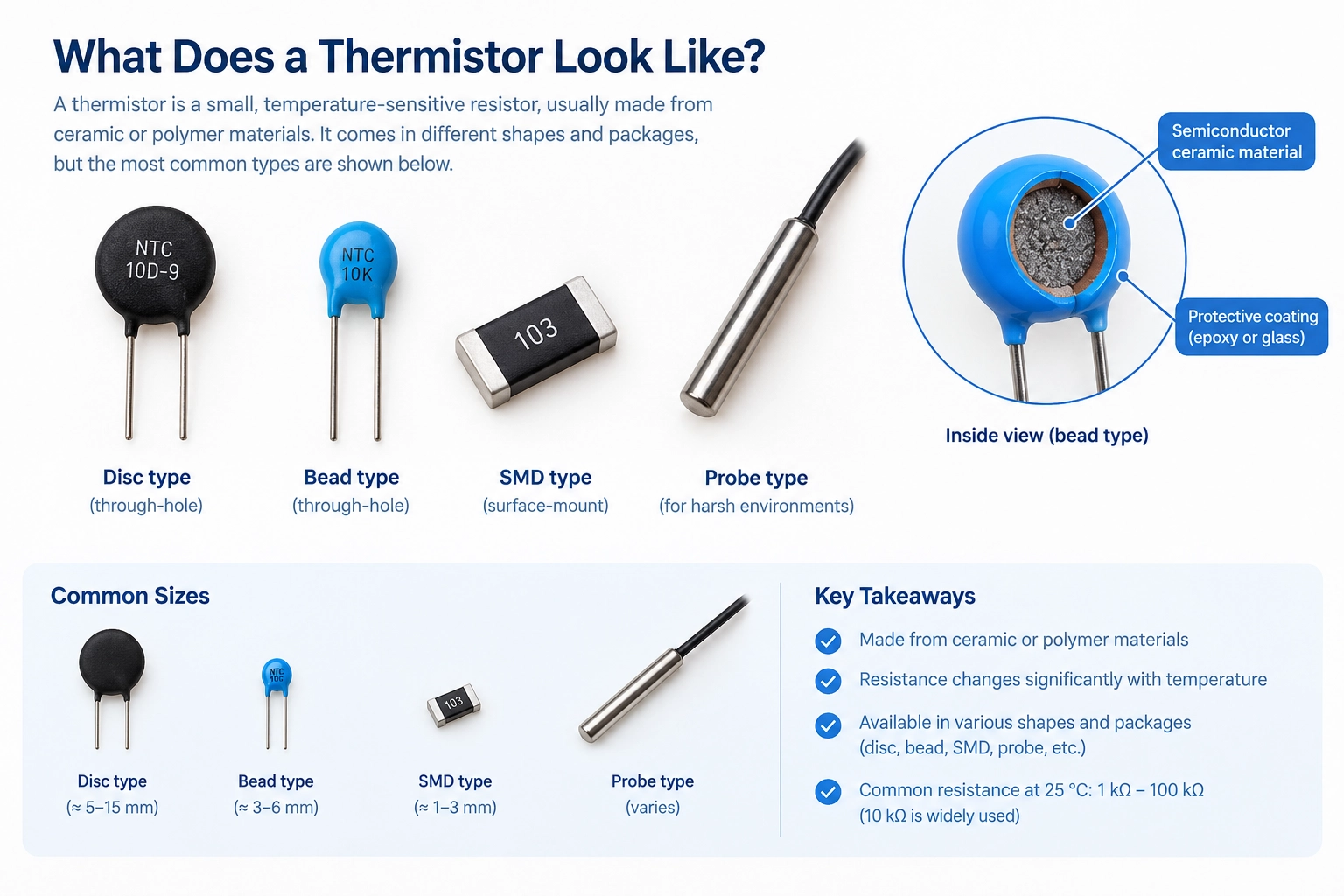
What Is a Thermistor?
A thermistor is a temperature-sensitive resistor made from a ceramic or polymer material whose resistance changes by a large, predictable amount with temperature. Thermistors belong to the family of non-linear resistors. An ordinary thick-film chip resistor typically changes by about 0.01% per °C (100 ppm/°C).
For example, a common 10 kΩ, 3950 K NTC thermistor changes by about 4.4% per °C near 25 °C, several hundred times more.
| Feature | Thermistor |
|---|---|
| Full name | Thermally sensitive resistor |
| What changes | Resistance, as the thermistor's own temperature changes |
| Main types | NTC (resistance falls with heat) and PTC (resistance rises with heat) |
| Common materials | Sintered oxides of manganese, nickel, and cobalt (NTC); doped barium titanate or conductive polymer (PTC) |
| Common resistance | 1 kΩ to 100 kΩ at 25 °C for NTC sensors; 10 kΩ is a widely used value |
| Typical temperature range | About −50 °C to 150 °C; specialized glass-encapsulated types can reach 300-500 °C. |
A thermistor measures its own temperature, which depends on the temperature of the object or the surrounding air it is in contact with. The current flowing through the thermistor can also heat it slightly, affecting the measurement.
How Does a Thermistor Work?
A thermistor works because temperature changes how easily current flows through its material.
In an NTC thermistor, as temperature increases, conduction increases, so resistance decreases.
In a PTC thermistor, heat makes conduction harder, so resistance rises, often sharply above a switch temperature.
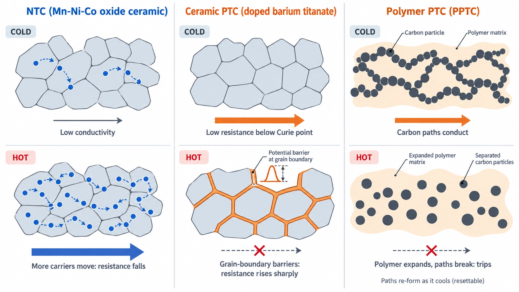
Figure: Side-by-side view of NTC metal-oxide grains, PTC grain boundaries
How Does an NTC Thermistor Work
NTC thermistors are made from sintered metal oxides, typically of manganese, nickel, and cobalt, which are fired into a semiconducting ceramic. Conduction in these oxides is thermally activated. As the temperature rises, more charge carriers can move between the metal ions, so the conductivity rises and the resistance falls exponentially.
How Does a PTC Thermistor Work
Switching PTC thermistors are made in one of two main forms:
- Ceramic PTC: Doped barium titanate has low resistance below its Curie temperature. Above it, the potential barriers at the ceramic grain boundaries rise sharply, and resistance rises by several orders of magnitude over a narrow temperature range.
- Polymer PTC (PPTC): Carbon particles in a crystalline polymer form conductive paths. When overcurrent heats the polymer, it expands, separates the particles, and resistance rises sharply. As it cools, the paths re-form, which is why PPTC devices are called resettable fuses.
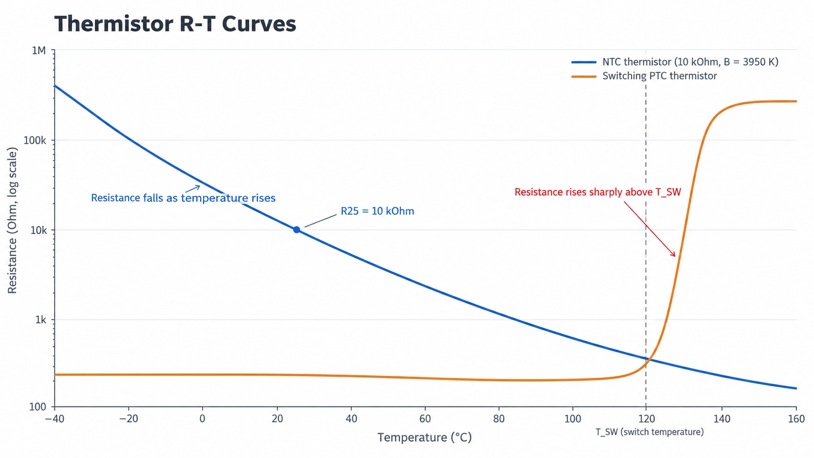
Figure: NTC and PTC thermistor resistance versus temperature curve.
NTC vs. PTC Thermistors: Key Differences
The difference lies in the direction of change: an NTC thermistor's resistance decreases as temperature rises, whereas a PTC thermistor's resistance increases, so the two types serve different roles.
In short, NTC thermistors are mainly used to measure temperature, while switching PTC thermistors are mainly used to protect circuits.
| Property | NTC Thermistor | PTC Thermistor |
|---|---|---|
| Resistance as temperature rises | Falls smoothly and exponentially | Changes little, then rises steeply above the switch temperature |
| Typical material | Sintered manganese, nickel, and cobalt oxides | Doped barium titanate or conductive polymer |
| Temperature coefficient | About −3% to −5% per °C near 25 °C | Large and positive values above the switch temperature |
| Main jobs | Temperature sensing, temperature compensation, and inrush current limiting | Resettable overcurrent protection, overtemperature detection, and self-regulating heaters |
| Key datasheet values | R25, B value, and tolerance | Switch temperature, hold current, and trip current |
| IEC symbol label | −t° | +t° |
Note
- Choose NTC for: measuring temperature over a continuous range, or limiting inrush current at power-on.
- Choose PTC for: limiting fault current or detecting overtemperature, where the circuit needs a large resistance change at a defined point.
Thermistor Applications: Where Thermistors Are Used
Thermistors are used wherever a circuit needs to measure temperature at low cost, limit current at power-on, or protect itself against overcurrent or overheating, from battery packs to 3D printers.
| Application | Thermistor Type | What It Does |
|---|---|---|
| Board temperature sensing | NTC, SMD chip | Let the microcontroller monitor a power stage and reduce power when it overheats |
| Battery packs and chargers | NTC, often 10 kΩ | Let the charger or battery management system pause charging when the cell temperature is outside its allowed range |
| 3D printer hotends and heated beds | NTC, often 100 kΩ | Feeds the printer's temperature controller |
| Power supply inputs | Power NTC disc | Limits the inrush current when the supply switches on |
| USB ports and battery outputs | PPTC | Trips on overcurrent and resets after the fault is removed and the device cools |
| Motor and transformer windings | Ceramic PTC | Detects winding overtemperature |
| Appliance heaters | Ceramic PTC heater, NTC probe | Self-regulates heater temperature; measures air or water temperature |
| Temperature compensation circuits | NTC | Offsets the temperature drift of other components, such as crystal oscillators |
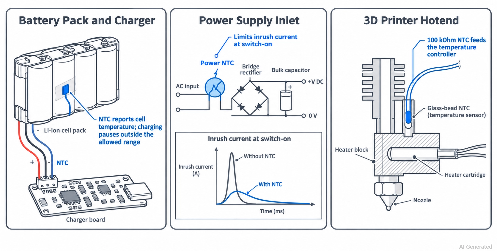
Figure: Application map showing thermistors in a battery charger, a power supply inlet, and a 3D printer hotend.
Two applications use the thermistor to control current rather than to sense temperature:
- NTC inrush current limiting: A power NTC in series with the supply input typically measures a few ohms when cold, which limits the charging current of the bulk capacitor at switch-on. Load current then heats it, and its resistance drops to a small fraction of the cold value.
- PPTC resettable fuse: Below its hold current, a PPTC adds only a small series resistance. Above its trip current, it heats, switches to a high-resistance state, and limits the fault current until power is removed and it cools.
In a 3D printer, the firmware setting should match the exact thermistor model. Two 100 kΩ thermistors with different curves can read 10–20 °C apart at printing temperatures, as explained in this 3D printer heated bed upgrade guide.
Types of Thermistors by Construction
Thermistors are built in several physical forms. The construction sets much of the temperature range, response speed, and mounting method of the finished part.
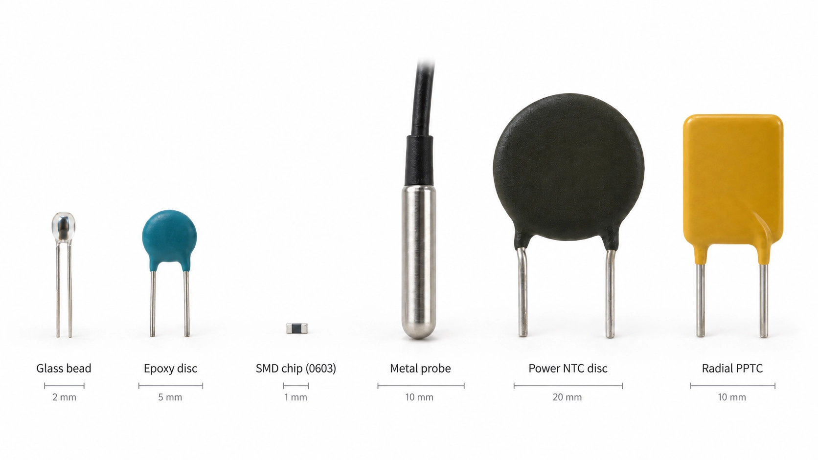
Figure: Thermistor types, including a glass bead, epoxy disc, SMD chip, metal probe, power NTC disc, and radial PPTC.
| Type | Construction | Typical Use |
|---|---|---|
| Glass-encapsulated bead | Small bead sealed in glass | High temperatures, up to about 300 °C, such as 3D printer hotends |
| Epoxy-coated disc or bead | Leaded element dipped in epoxy | Low-cost general sensing at moderate temperatures |
| SMD chip | Ceramic chip with end terminations | Board temperature sensing, battery packs, and compensation |
| Probe or lug assembly | Element sealed in a metal tube or ring lug | Liquids, air ducts, and heat sinks |
| Power NTC disc | Large disc with a low cold resistance | Inrush current limiting |
| Ceramic PTC disc | Doped barium titanate disc with leads | Overcurrent protection, overtemperature sensing, and heaters |
| Polymer PTC (PPTC) | Conductive polymer in radial-leaded or SMD packages | Resettable fuses on ports and battery outputs |
SMD thermistors are available in standard chip package sizes, such as 0402 and 0603, that are also commonly used for SMD resistors. See our guide to SMD resistor package sizes for package dimensions and size-code references.
Thermistor Specifications: How to Read a Thermistor Datasheet
An NTC thermistor is defined mainly by two numbers: R25, its resistance at 25 °C, and the B value, which sets the slope of its curve. Tolerance, dissipation constant, and thermal time constant then set its accuracy and response speed.
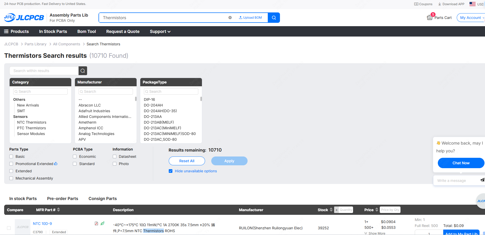
Example values are from Murata's NCP18XH103F03RB, a widely used 10 kΩ NTC in a 0603 package.
| Specification | What It Means | Example Value |
|---|---|---|
| R25 | Resistance at 25 °C | 10 kΩ |
| Resistance tolerance | Allowed deviation of R25 | ±1% |
| B value (B25/50) | Slope of the curve between 25 °C and 50 °C | 3380 K ±1% |
| Dissipation constant | Power that raises the thermistor 1 °C above its surroundings | 1 mW/°C |
| Maximum operating current | Murata's limit for 0.1 °C of self-heating | 0.1 mA at 25 °C |
| Operating temperature range | The temperature range the part is rated for | −40 °C to 125 °C |
| Thermal time constant | Time to reach 63.2% of a step change in temperature | Depends on the package and the surrounding medium |
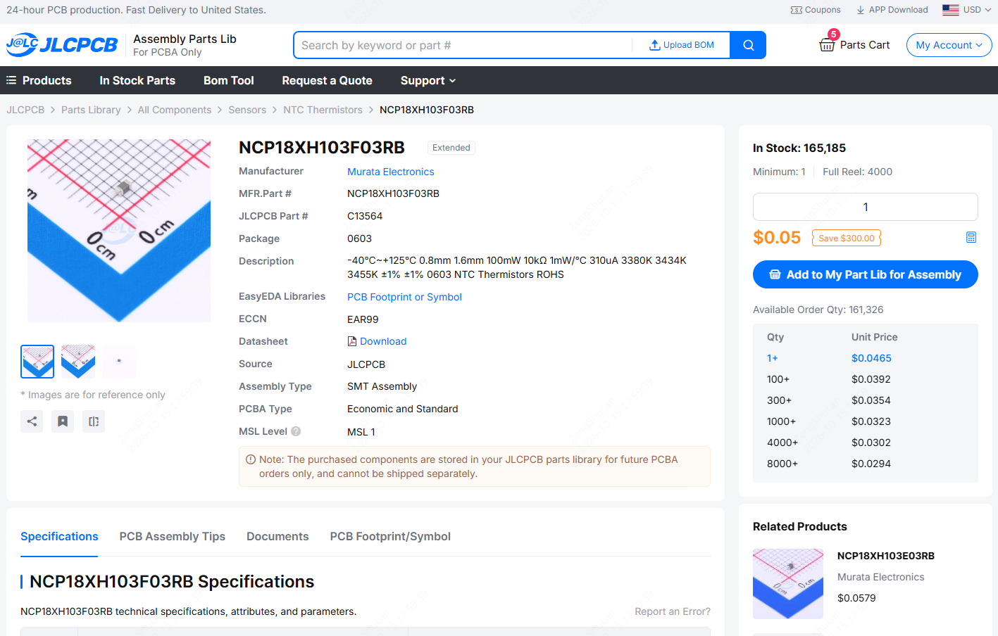
https://jlcpcb.com/partdetail/MurataElectronics-NCP18XH103F03RB/C13564
How to Use a Thermistor in a Circuit: Voltage Divider and ADC
The most common way to read an NTC thermistor is a voltage divider: the thermistor and a fixed resistor in series across a supply, with the midpoint connected to an ADC input. Firmware converts the reading to resistance, then to temperature.
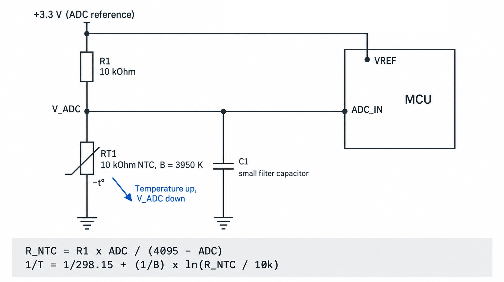
Figure: Schematic of a 10 kΩ NTC thermistor and a 10 kΩ resistor connected to a microcontroller ADC pin.
- Choose the fixed resistor: Set it equal to the thermistor's resistance at the middle of the temperature range you need. For room temperature, a 10 kΩ resistor with a 10 kΩ NTC gives half the supply voltage at 25 °C.
- Connect the divider: Place the NTC between the ADC pin and ground, and the fixed resistor between the ADC pin and the supply. The pin voltage then falls as temperature rises.
- Supply the divider from the ADC reference: When the divider and the ADC share the same reference, supply variations largely cancel out. This is called a ratiometric measurement.
- Convert the reading to resistance: For a 12-bit ADC, R_NTC ≈ R_fixed × ADC / (4096 − ADC).
- Convert resistance to temperature: Apply the Beta equation, the Steinhart-Hart equation, or a lookup table built from the datasheet's R-T table.
For a 10 kΩ, 3950 K NTC with a 10 kΩ fixed resistor on 3.3 V, the Beta equation gives these values:
| Temperature | NTC Resistance | ADC Pin Voltage | 12-Bit ADC Count |
|---|---|---|---|
| 0 °C | 33.6 kΩ | 2.54 V | 3156 |
| 25 °C | 10.0 kΩ | 1.65 V | 2048 |
| 50 °C | 3.59 kΩ | 0.87 V | 1081 |
| 75 °C | 1.49 kΩ | 0.43 V | 532 |
| 100 °C | 698 Ω | 0.21 V | 267 |
Thermistor vs. RTD vs. Thermocouple vs. IC Temperature Sensor
A thermistor typically offers the highest sensitivity at the lowest cost over a moderate temperature range. An RTD is more linear and stable; a thermocouple covers the highest temperatures; and an IC sensor provides a linear or digital output without curve-fitting calculations.
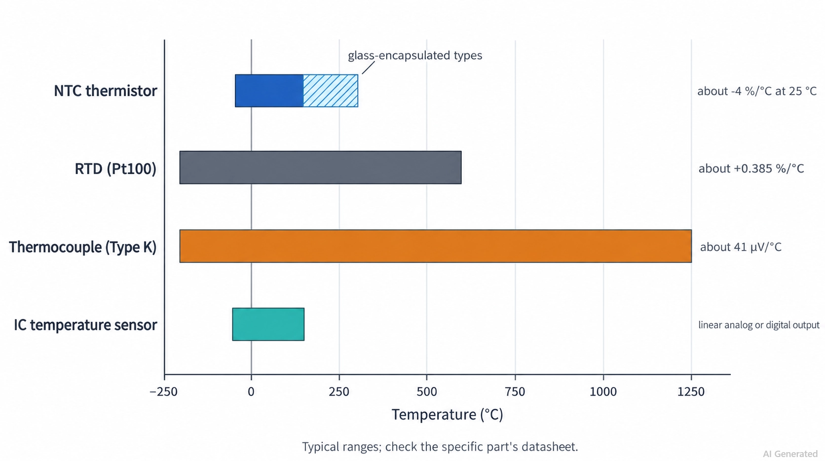
Figure: Temperature range chart comparing NTC thermistors, RTDs, thermocouples, and IC temperature sensors.
Thermistors are one of four common families of electronic temperature sensors:
| Property | NTC Thermistor | RTD (Pt100) | Thermocouple (Type K) | IC Temperature Sensor |
|---|---|---|---|---|
| Sensing principle | Resistance of a metal-oxide ceramic | Resistance of platinum | Voltage from two joined metals | Silicon junction with on-chip conversion |
| Typical range | −50 °C to 150 °C; glass types to about 300 °C | −200 °C to 600 °C | −200 °C to 1,250 °C | −55 °C to 150 °C |
| Sensitivity | About −4% per °C at 25 °C | About +0.385% per °C | About 41 µV/°C | Linear analog voltage or digital reading |
| Linearity | Strongly non-linear | Nearly linear | Slightly non-linear | Linear |
| Typical accuracy | ±0.1 °C to ±1 °C, depending on grade | ±0.15 °C at 0 °C for Class A | ±1.5 °C to ±2.5 °C for standard tolerance classes | ±0.1 °C to ±2 °C, depending on the part |
| Interface | Divider and ADC | Excitation current and ADC | Amplifier with cold-junction compensation | I²C, SPI, or analog pin |
| Relative cost | Lowest | High | Low sensor cost, higher interface cost | Low to moderate |
Thermistor Symbol: NTC and PTC in Schematics
A thermistor symbol is a resistor symbol crossed by a diagonal line with a short horizontal end, indicating that its resistance varies nonlinearly with a physical quantity. A "−t°" label marks an NTC thermistor, and "+t°" marks a PTC thermistor.
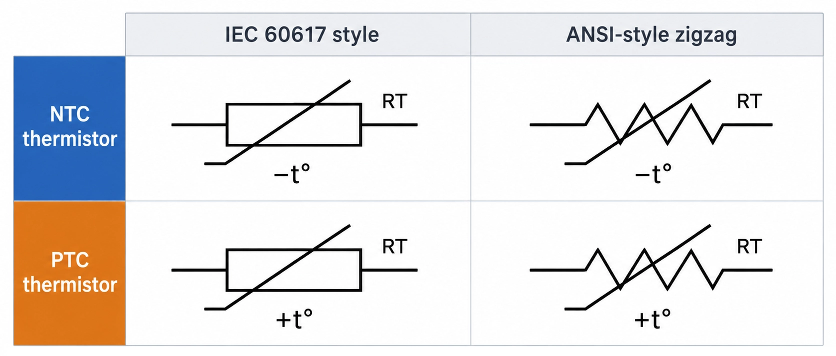
Figure: Thermistor symbol chart comparing IEC rectangle and ANSI symbols.
| Symbol Element | IEC 60617 Style | ANSI-Style Zigzag |
|---|---|---|
| Resistor body | Rectangle | Zigzag |
| Variation mark | Diagonal line with a short horizontal end | Commonly, the same bent diagonal line |
| NTC or PTC label | −t° or +t° next to or under the rectangle | −t° or +t°, or "NTC" or "PTC" written beside the symbol |
| Reference designator | Commonly RT or TH | Commonly RT or TH |
How to Place a Thermistor on a PCB
Place a thermistor close to the heat source it monitors and away from the heat sources it should ignore, because the surrounding copper sets the temperature it reads.
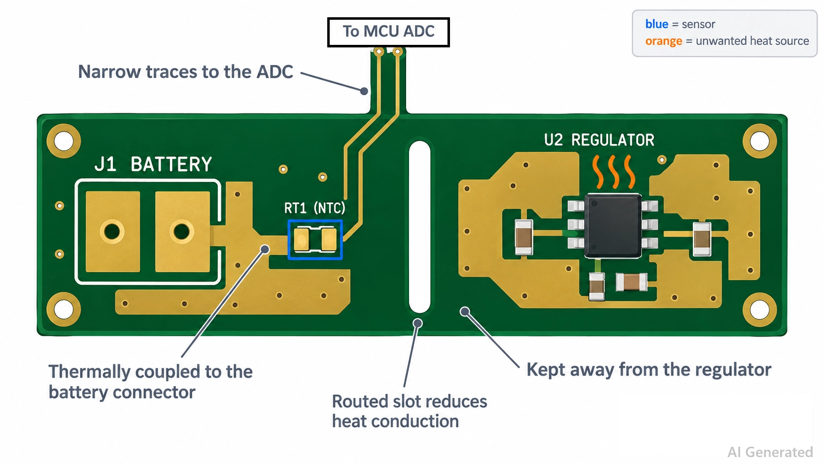
Figure: PCB layout with an SMD NTC thermistor beside a battery connector.
- Couple it to the target: Place the thermistor next to the battery, MOSFET, or connector it monitors, and connect one of its pads to the same copper area, such as the ground pour under the monitored part, where the circuit allows.
- Isolate it from other heat: Keep it away from regulators, power resistors, and inrush NTCs, which run hot under load. Distance or a routed slot reduces the heat conducted through the board.
- Sense air with thin connections: To measure air temperature, use narrow traces and keep the thermistor off large copper pours.
- Filter the ADC input: Place a small capacitor from the ADC pin to ground near the microcontroller to reduce noise picked up on long sensor traces.
Conclusion
What is a thermistor? It is a temperature-sensitive resistor: an NTC thermistor's resistance falls as it heats up, while a PTC thermistor's resistance rises.
Use an NTC thermistor to measure temperature or limit inrush current, and use a PTC thermistor to protect a circuit against overcurrent or overtemperature. Matching the R25 and B values to the measurement range, holding and tripping current to the protected load, and positioning the board to the heat source help ensure accurate readings and reliable protection.
Once your design is ready, upload your files to JLCPCB to review assembly options and get an instant quote.
FAQs About Thermistors
Q: What Does 10K 3950 Mean on a Thermistor?
It means the thermistor measures 10 kΩ at 25 °C and has a B value of 3950 K, often specified between 25 °C and 50 °C. Together, the two numbers define the curve.
Q: How Do You Test a Thermistor with a Multimeter?
Measure its resistance at room temperature and compare it with the datasheet R-T table. Then warm it gently: an NTC's resistance should fall noticeably, while a switching PTC changes little below its switch temperature.
Q: Does a Thermistor Have Polarity?
No. A thermistor is a non-polarized resistive component, so it works the same in either orientation on the board.
Q: How Accurate Is a Thermistor?
Typically ±0.2 °C to ±0.3 °C at 25 °C for a ±1% R25 tolerance grade. Precision NTC thermistors can achieve an accuracy of about ±0.1 °C over the range 0 °C to 70 °C.
Q: What Does a Thermistor Do in a Battery Pack?
It measures the cell temperature. The charger or battery management system reads the NTC, typically 10 kΩ, and pauses charging or discharging when the temperature falls outside the allowed range.
Popular Articles
• SMD Resistor Package Sizes: Complete Size Chart, Footprints & How to Choose
• How to Solder SMD Components Like a Pro [2026 Updated]
• SMD Resistor Codes: How to Read 3-Digit, 4-Digit, and EIA-96 Markings
• SMD Capacitor Codes: Identification, Markings, and Polarity
• SMD Capacitor Sizes: Complete Size Chart and Selection Tips for PCB Design and Assembly
Keep Learning
ESP8266 vs ESP32: Which One Should You Use?
Key Takeaways ESP32: Dual-core 240 MHz CPU, Bluetooth Classic and BLE, 520 KB SRAM, and up to 34 GPIOs. ESP8266: Single-core CPU, no Bluetooth, and around 50 KB of free RAM for applications. Lifecycle status: Espressif marks the ESP8266 Not Recommended for New Designs (NRND) and names the ESP32-C2 (ESP8684) as its upgrade, although the ESP8266 remains in production with a longevity commitment. Which ESP32 to use: Choose the ESP32-C2 for simple Wi-Fi or Bluetooth LE firmware, the ESP32-C3 for more memo......
What Is a Thermistor? A Practical Guide to NTC, PTC, Applications, and Circuit Design
Key Takeaways Definition: A thermistor is a thermally sensitive resistor whose resistance changes markedly and predictably with temperature, typically by about 4.4% per °C for a standard 10 kΩ NTC (B25/50 = 3950 K) near 25 °C. NTC vs. PTC: An NTC thermistor's resistance falls as temperature rises, which suits temperature sensing and inrush current limiting; a switching PTC's resistance rises steeply above its switch temperature, which suits circuit protection. Key Specifications: An NTC thermistor is ......
What Is the ESP32-CAM, and How to Wire, Power, and Program It?
Key Takeaways Board, not chip: The ESP32-CAM is an AI-Thinker development board, not an Espressif product. It carries AI-Thinker's ESP32-S module, an OV2640 camera, PSRAM, a microSD slot, and a flash LED. No USB port: The board has no USB connector or USB-to-UART bridge, so you program it via its serial pins using a 3.3 V USB-to-serial adapter, with GPIO0 held low at reset. Few free pins: The camera, PSRAM, and microSD card occupy most GPIOs. With the microSD card unused, GPIO2, GPIO4, GPIO12, GPIO13,......
ESP32 Versions: Which One Should You Use for Your Project?
Key Takeaways Radios decide first: ESP32 versions differ mainly in their radios, CPU cores, and peripherals. Common defaults: The ESP32-C3 suits low-cost Wi-Fi and Bluetooth LE, the ESP32-S3 suits camera, display, voice, and on-device AI. Original ESP32: The chip is still in production and remains the choice for Bluetooth Classic. Versions without Wi-Fi: The ESP32-H2 targets battery-powered Thread and Zigbee devices. Chip, module, or board: Prototype on a development board, then design a module onto y......
SOIC Package: A Complete Guide to Specifications, Types, Uses, and SMT Assembly
As designs transition from legacy through-hole components to high-density Surface Mount Technology (SMT), the Small Outline Integrated Circuit (SOIC) remains the industry standard for operational amplifiers, flash memory, sensors, and microcontrollers. It reflects a well-balanced engineering design, offering a practical compromise between the miniaturisation demanded by modern consumer electronics and the ruggedness required for industrial applications. In this guide, you will learn: SOIC package dime......
What Is a 100nF Capacitor and How Do You Choose the Right One
Key Takeaways Value: A 100nF capacitor has a nominal capacitance of 0.1 µF, or 100,000 pF, and all three names describe the same part value. Marking: Many through-hole ceramic and film capacitors use the three-digit code 104, while most SMD MLCCs are unmarked. Main use: Its most common function is local decoupling at an IC power pin, where it supplies fast transient current and shunts high-frequency noise to ground. Default choice: For general decoupling, an X7R or X5R MLCC is a common starting point;......