The Smart Advantages of Rounded Corners in Modern PCB Design
13 min
- Understanding Rounded Corners in PCB Fabrication
- Key Benefits of Using Rounded Corners
- Design Considerations for Effective Rounded Corners
- Manufacturing Challenges and Precision Solutions
- JLCPCB's Expertise in Precision Rounded Corner Production
- FAQ about PCB Rounded Corner
- Conclusion
Key Takeaways
- Rounded corners reduce stress concentration and prevent chipping, cracking, and delamination.
- They improve safety, handling, and perfect fit in enclosures with matching radii.
- Use R0.5–R1.0 mm for small boards, R1.0–R2.0 mm for standard designs.
- Internal corners must respect router bit limits (min. R0.5 mm); external corners are more flexible.
- Maintain 0.3–0.5 mm edge clearance and use CNC routing with mouse bites for panelization.
- No extra cost — highly recommended for reliability and professional appearance.
Ever get a new board out of an enclosure and find that the corners are slightly rounded? That's no beauty accident. A Rounded Corner is an intentional design decision that, in itself, addresses multiple mechanical and manufacturing challenges. The problem is, sharp 90-degree corners are stress magnets. They chip when de-paneling, crack when shaken, snag ribbon cables, and can even slice a careless thumb when being assembled.
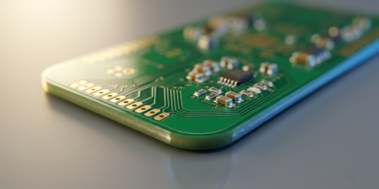
This curving of these corners helps distribute forces, prevents laminate damage at the edge, and makes the board easier to handle. Let's discuss the role rounded corners play in modern boards today, the advantages they provide, some design principles that dictate the use of radius, how to draw a rounded corner in your design software, and how a fabricator will transform that geometry into a clean, repeatable edge. Let's dig in.
Understanding Rounded Corners in PCB Fabrication
Let's get to the specifics of what we are adding to the board outline and why it's there, before we discuss benefits.
What Rounded Corners Are and Their Primary Purposes
A rounded corner (also known as a filleted or radiused corner) is when a hard right angle on a board is made into a circular arc of a specified radius. In your design, it exists on the layer that defines the outline of the board, e.g., the `Edge.Cuts` layer in KiCad, the board shape layer in Altium, or the Board Outline layer in EasyEDA.
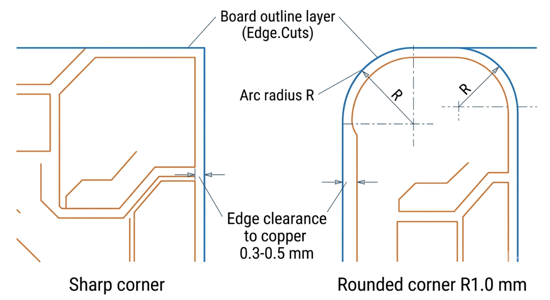
The radius is described in millimeters like R0.5, R1.0, R2.0, etc. The higher the number, the flatter the curve. The main function of a PCB rounded corner is just fourfold:
- Stress relief: A stress distribution is provided by an arc, which relieves the mechanical load rather than focusing it at a single point.
- Curved edges provide edge protection: Curved edges prevent chipping, cracking, and delamination during routing operations and handling.
- Safe handling: No sharp points to cut fingers or snag wires when put together.
- Mechanical fit: The board will fit into a molded enclosure with the same radius on the inside so it sits flat.
To sum up, rounding a corner is a low-cost way of insuring against an entire class of mechanical failures.
Common Applications Across Different Industries
Whether you're looking at consumer products that imitate the rounded shape of products they contain or rugged industrial boards that must endure the inevitable vibrations of a demanding work environment, rounded corners are everywhere! Some common markets and their reasons for using the feature:
- Consumer Devices: Cosmetic matches to curved plastic housings and edge-to-edge form.
- Aerospace: Vibration resistance and long-term mechanical reliability in automotive and aerospace.
- Medical and wearable: Safe, snag-free handling and rounded product ergonomics.
- LED lighting and power modules: Clean insertion into extruded aluminum channel and heatsinks.
The shape is a recurring one: A rounded corner is not usually just a decoration; it is a real mechanical or ergonomic need.
Key Benefits of Using Rounded Corners
Let's get to the juicy part in a Design Review. When you list the advantages of rounded corners, you can see how important it is.
Improved Mechanical Strength and Stress Distribution
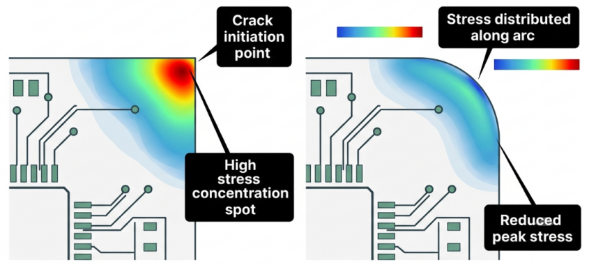
A corner that is sharp is a typical stress concentration. Mechanical stress accumulates at that single vertex when the board bends, whether it's during depaneling, mounting, or a drop event, and it's the one place where cracks tend to form. The rounded corner reduces the stress point, therefore reducing the risk of cracking or lifting of the copper at the corner, similar to how engineers fillet the inside corner of a metal bracket. It's just one change that can mean the difference in surviving the service life or experiencing hairline fractures at the corners of the board, if the boards are subject to vibration or repeated flexing.
Enhanced Safety, Aesthetics, and Assembly Handling
Facing it, nobody wants to deal with a board with sharp corners that look like little knife points. Rounded corners ensure safe assembly for operators and improved protection for the nearby harness, gasket, and ribbon cable. There's a quality perception angle as well. A cleanly radiused edge is more finished, more professional, especially if it's a product that a customer will hold, and during pick-and-place, less chance to snag on tooling. Fewer nicked fingers and a big impression with small detail.
Better Durability During Shipping and Daily Use
The first place to chip when boards hit each other in a tray or shipping tube is at the sharp corners, and a small chip can start to delaminate or crack a trace over time. Rounded corners are much more forgiving, since there is no fragile point that can get caught on impact with another object; the edge remains fine during transport, storage, and years in the field.
Let's just quickly compare what rounding a corner does:
| Characteristic | Sharp 90° Corner | Rounded Corner |
|---|---|---|
| Stress concentration | High (single point) | Low (spread along arc) |
| Chipping/cracking risk | Elevated | Reduced |
| Handling safety | Poor (sharp points) | Good (smooth edge) |
| Enclosure fit | Gaps at molded radii | Flush seating |
| Depaneling cleanliness | Prone to burrs | Cleaner edge |
Design Considerations for Effective Rounded Corners
While it is easy to add a radius, it requires some design considerations to add the right radius the right way. If you get these right, your board will go straight in for fabrication without a DFM query.
Optimal Radius Selection and Placement Guidelines
There are typically two factors that affect the best radius: the enclosure it fits into and the size of the board. If your board is mounted inside a molded case, make the corner radius the same as the fillet on the inside of the case to ensure the board fits flush.
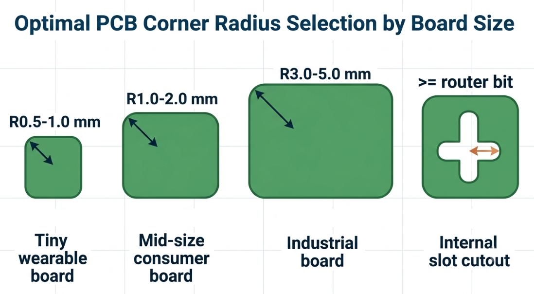
Generally speaking, the bigger the board, the bigger the radius that can be accommodated without waste. A good starting point is:
| Application / Board Size | Suggested Corner Radius | Notes |
|---|---|---|
| Small/wearable (< 30 mm) | R0.5 – R1.0 mm | Preserve scarce edge area |
| Standard consumer (30–100 mm) | R1.0 – R2.0 mm | Good general-purpose choice |
| Large/industrial (> 100 mm) | R3.0 – R5.0 mm | Match big enclosure radii |
| Slot/cutout inside board | ≥ router bit radius | Cannot be sharper than the tool |
Some of the tips for placement that can be followed:
- Ensure copper, pads, and traces are at least N (Normal) Edge clearance (0.3-0.5 mm) away from the arc.
- Round all four corners unless one needs to remain square for keying or a datum feature.
- When cutting out on the inside for cutouts or notches, keep in mind that the corner cannot be sharper than the routing bit (more about that later, too!).
Integration with Panelization and Board Outline Rules
Rounded corners are directly coupled with panelization. Since the curved edge needs to be milled, the boards with rounded corners are cut off with breakaway tabs or mouse-bites, which can only cut straight lines. In laying out a panel, allow space for the router bit to run all the way around each corner; set breakaway tabs on straight edge segments, not the arcs. This prevents the curved corner from getting dirty and burrs after depaneling. Make sure your board outline is a single, non-overlapping closed contour as well; holes and overlapping or duplicate outline segments are a frequent source of manufacturing delays.
Using Design Software to Implement Rounded Corners Accurately
There are several different ways to achieve a rounded corner in all of the major design software packages. The main thing is to follow the arc on the designated board outline layer for CAM to see it as a mechanical edge.
- KiCad: On the Edge. Cut the layer, draw the outline using the line tool, select two line segments that meet, right click, and then click Fillet Lines, and type in the radius (e.g., 1.0 mm). Arcs can also be drawn with the Arc tool.
- Altium Designer: In board-planning mode, set the shape of the board and then use Design Board Shape and place arcs at each corner or draw the arcs on a mechanical layer using the Arc tool and specify the radius numerically.
- EasyEDA: Use the Board Outline layer to draw an outline, or use the Arc tool, or place a rounded rectangle and set the corner radius. EasyEDA has a close relationship with the fabrication, and it is convenient to verify the outline before placing orders.
No matter which tool you are using, be sure to enter the radius number, don't just eyeball it, and design rule check the outline to ensure it exports without problems to Gerber.
Manufacturing Challenges and Precision Solutions
Merely drawing the corner is half. When that arc is turned into a real edge, some manufacturing realities come into play.
CNC Routing Techniques and Tolerance Control
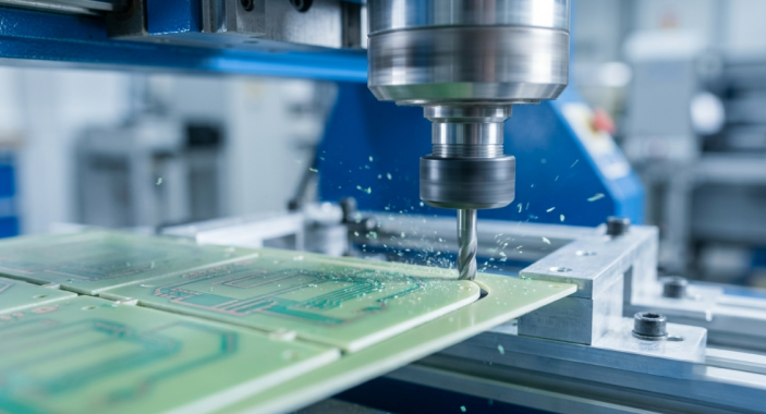
With a CNC machine, a rotating router bit removes rounded corners by following your board outline. The most important factor is the bit radius; an inside (concave) corner cannot be sharper than the cutting tool that creates it. A typical outline bit may be about 1.0mm in diameter, and therefore, the smallest internal radius it can form is approximately R0.5mm. Request anything steeper than that, and the router will not be able to reach the inside corner, instead giving you a corner with the radius of the bit.
The board has no such restriction on the radius of the external corners (which are convex), and can be curved to nearly any radius desired. The typical board outline dimensional tolerance is about ±0.2 mm with quality CNC routing. Good fabricators manipulate the feed rate, spindle speed, and bit wear to maintain that number and to prevent the edge from running burrs and delaminating.
Quality Assurance for Consistent Corner Quality
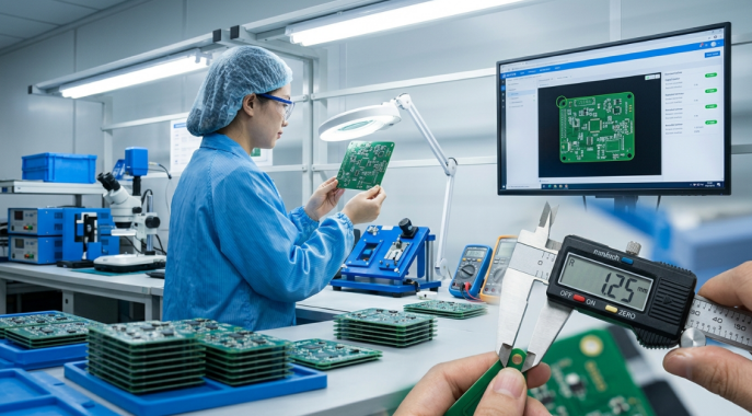
Disciplined inspection, not luck, brings consistent corners. Following routing, boards are inspected for dimensional accuracy, smooth edges, chipping, and any areas of laminate raised. Typical QA procedure typically involves:
- First article dimensional check: The dimensions of radius and outline are checked using calipers or a CMM against Gerber.
- Visual and edge inspection: Operator inspects edge looking for burrs, nicks, and delamination against IPC-A-600 acceptability criteria.
- Tab and mouse-bite review: The breakaway points are verified to be clean, so they do not stress the corner.
The cost of catching an out-of-tolerance corner at first article is much less than after a full production run.
JLCPCB's Expertise in Precision Rounded Corner Production
Knowing what to do is one thing; achieving repeatable and crisp corners on each and every board is another. This is where a good fabrication partner comes in.
Advanced CNC Equipment with Tight Tolerance Capabilities
JLCPCB supports board outline routing on modern CNC machines, which has a board outline tolerance of about ±0.2 mm, and can support routing board outline with an internal radius of about R0.5 mm in the case of using a 1 mm routing bit. This precision translates into the fact that your rounded corners appear exactly as you drew them, rather than an approximation. Using controlled spindle speeds and fresh tooling ensures that edges are clean and burr-free, so that boards drop straight into their enclosures, requiring no hand filing.
Professional DFM Feedback for Optimized Board Outlines
All orders go through automated and human Design for Manufacturability (DFM) review. Outlines with an internal radius smaller than the router bit can cut, open contours, and breakaway tabs that don't fit well on a curve get flagged before the production process begins, which means that potential scrap runs become quick fixes.
The corners on your five-piece prototype are the same as those on a thousand-piece production batch, since the same routing process is used and the same inspection process. PCBs are as low as $2 with quick turnaround, allowing you to cheaply test a rounded-corner design and then go ahead and ramp. JLCPCB's instant quoting and CNC routing make it easy to have boards with clean and accurate rounded corners.
FAQ about PCB Rounded Corner
Q: What is the smallest rounded corner radius I can use on a PCB?
For internal (concave) corners, the minimum radius equals the routing bit radius, typically about R0.5 mm with a 1 mm bit. External board corners can be rounded much more tightly since they are not limited by the tool.
Q: Do rounded corners cost more than square corners?
Usually not. Rounded corners are produced by the same CNC routing step used to separate boards, so as long as the radius is manufacturable, there is generally no extra charge.
Q: Can I use V-scoring with rounded corners?
No. V-scoring only cuts straight lines, so rounded corners require CNC routing with breakaway tabs or mouse-bites for depaneling. You can still mix routed corners with V-scored straight edges on the same panel.
Q: How do I add a rounded corner in my design software?
Draw the outline on the board outline layer, then apply a fillet or place an arc at each corner with an explicit radius. KiCad uses the Fillet Lines command on the edge. Cuts, while Altium and EasyEDA let you place arcs or a rounded rectangle.
Q: What board outline tolerance should I expect for rounded corners?
With quality CNC routing, expect a board outline tolerance of about ±0.2 mm. Confirm your fabricator's routing bit size so your internal radii stay within what the tool can physically cut.
Conclusion
One of those little things that will pay off in spades is a rounded corner. This one arc on the outline layer reduces mechanical stress, secures the edge of the laminate, prevents injuries for the operators, and ensures a good seating of the board in its enclosure.
It's not that complicated once you stay within two parameters: you must select a radius that fits the size of your board and of your enclosure, and you must never request an internal corner angle smaller than the one that the routing bit can cut. Nail those and keep your outline a nice, clean, closed contour, and export the arc on the proper layer. With electronics continuing to get smaller and enclosures more sculpted, rounded corners will soon be the norm, not the exception. JLCPCB's precision CNC routing and feedback through DFM ensure crisp and reliable rounded corners from the first prototype to volume production.

Keep Learning
How Laser-Made PCBs Are Used in Rapid Prototyping
Key Takeaways Speed & Precision: Digital lasers enable 24-hour quick-turn HDI and FPC prototyping without mechanical tooling. LDI Patterning: Replaces physical photo-films to deliver precise circuit traces down to 2/2 mil. HDI Microvias: UV/CO2 lasers drill 0.075–0.15 mm blind vias (1:1 aspect ratio) for 1+N+1 to 3+N+3 stackups. Laser Profiling & Stencils: Achieves ±0.05 mm FPC cut accuracy and ±0.003 mm LPKF stencil aperture precision. Laser DFM: Maintain ≥ 0.30 mm copper clearance on FPCs and ≥ 0.07......
A Beginners Guide to Tented vs Untented Vias
Via’s are important, If working at high speed design and HDI boards then they become super important. Choosing a type of via during PCB manufacturing matters. Via’s are basically joining two or more layer traces together. Shape, size and track length guidelines became more interesting at high frequency and high speed signals. Today in this article we will explore a fabrication side, the decision to use tented or untented vias. This beginner-friendly guide explains what tented vias are, the differences......
Understanding SMT PCB Boards Technology: An Essential Component of Modern Electronics
Surface Mount Technology (SMT) has changed manufacturing of modern electronics. It has made designs and assembly methods more efficient. Many modern electronics depend on SMT PCB boards, which make it possible for circuit designs to be small and efficient. This is what today's technology needs. This article discuss about many types of SMT PCB boards, their uses, and the best methods for designing and assembling them. 1. What is an SMT PCB Board? Printed circuit boards called SMT PCB boards, use surfac......
How to Choose the Right Prepreg Material for Reliable Multilayer PCB
Have you ever wondered what makes all those copper layers stick to a cross-section of a multilayer PCB? Prepreg material is the answer, and it is of much more importance than most engineers think it is. Choose the prepreg selection wrong, and you are predetermined to delamination, impedance drift, and long-term reliability problems. Prepreg is not only glue. It is a designed composite that determines your dielectric separation, dictates your impedance, affects signal loss, and determines your board be......
Via Filling Explained: Key Techniques, Benefits, and Solutions for High-Performance PCBs
Key Takeaways Via filling completely fills plated through-holes and microvias with epoxy or conductive copper paste, followed by planarization and copper capping (POFV). It eliminates voids, solder wicking, and thermal/mechanical issues while enabling reliable via-in-pad designs. Benefits include superior heat dissipation (up to 8 W/m·K), better signal integrity, higher mechanical strength, and improved assembly yields. JLCPCB provides free non-conductive filling + POFV on 6+ layer boards. Ideal for H......
How Fiducial Markers Guarantee Perfect Alignment in Professional PCB Fabrication
Today, the most sophisticated pick-and-place machine can place a 0.5 mm pitch QFP on its footprint, board after board, thousands of times, and never miss. It is not only a matter of expensive cameras or high-quality servos, but it begins with a little, very small copper dot, simply hanging there in the corner of your PCB. That dot represents a fiducial marker, and without it, even the smoothest SMT line would be laying components in the dark. The unrecognized heroes of automated assembly are the fiduc......