How to Design and Manufacture Reliable Slot Holes in PCBs
14 min
- Understanding Slot Holes and Their Role in PCB Design.
- Key Benefits of Using Slot Holes
- Critical Design Considerations for Slot Holes
- Manufacturing Challenges and Precision Solutions
- JLCPCB's Advanced Capabilities in Slot Hole Processing
- FAQ about Slot Holes in PCBs
- Conclusion
Key Takeaways
- Slot holes are elongated openings ideal for flat pins, connectors, shields, and board alignment.
- Minimum sizes: 0.5 mm (plated) and 1.0 mm (non-plated); prefer rounded ends with length ≥ 2.5× width.
- Maintain proper annular ring, edge clearance, and DFM rules to prevent breakout and plating issues.
- Use overlapping drills for short plated slots and routing for longer ones.
- Good slot design greatly improves mechanical strength, thermal performance, and assembly reliability.
- JLCPCB’s precision processes and DFM feedback ensure consistent high-quality results from prototype to production.
Ever had to insert a rectangular power connector, a USB shield tab, or an oversized relay pin into a round hole? It just doesn't work out. That's where the slot hole comes in to quietly save your design. This is one of the most useful yet least understood features on a printed circuit board - an elongated, non-circular opening. The slot hole may seem insignificant when it comes to your Gerber file, but it is directly associated with mechanical strength, component fit, and manufacturability. Order the wrong size or tolerance, and you could end up with loose parts, plating issues, or a board that doesn't pass DFM. Do it right, and you'll be able to enjoy cleaner assemblies and more secure mounting. In this article, we will explore what a slot hole is, why engineers use it, the rules of design that make it reliable, and how modern manufacturers process it with accuracy. At the end of this article, you will have a clear idea of how to define a PCB slot hole that will make it from prototype to volume production.
Understanding Slot Holes and Their Role in PCB Design.
What Slot Holes Are and Common Applications
A slotted hole is a hole shaped in an elongated, oval, or rectangular pattern that can be created by combining two or more drill hits that overlap, or by routing a continuous hole. It is NOT a round hole, but rather a "stretched" hole, that is, it is longer than it is wide. This shape can be used to fit components that would never fit in a circular hole. Slot holes are more common than beginner slot players think they are. After you learn where to find them, you can see them in nearly every product category.
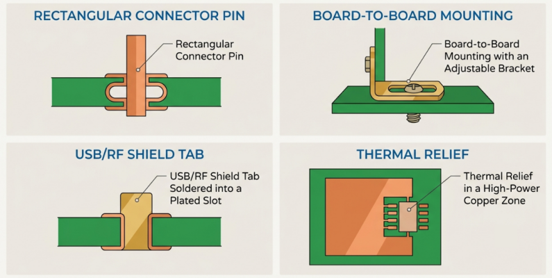
- Rectangular or Blade style pins: Power connectors, relays, and terminal blocks with flat leads fit snugly in slots.
- Board-to-board mounting: Slots provide some slight positional adjustment to enable parts to align during board-to-board mounting.
- Edge connectors and shields: They are soldered into plated slots for mechanical anchorage, which includes USB, HDMI, and RF shield tabs.
- Thermal and mechanical relief: Slots provide thermal and mechanical relief for high-power sections.
A slot spreads out the force to a longer contact area, making it a logical choice where mechanical stability is important. This is why slotted holes are so common in automotive, industrial, and power electronics boards.
Difference Between Slot Holes, Round Holes, and Milling
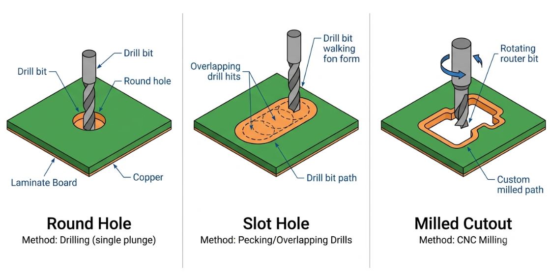
The best way to understand a slot hole is to visualize it as a hole of a certain shape, positioned between a round hole and a milled cutout. Every feature is produced in a different way and for a particular purpose. The table below outlines the main differences.
| Feature | Shape | Typical Method | Best Use Case |
|---|---|---|---|
| Round Hole | Circular | Single drill hit | Standard pins, vias, and screws |
| Slot Hole | Elongated/oval | Overlapping drills or routing | Flat pins, shields, and connectors |
| Milled Cutout | Any custom outline | CNC routing | Openings, board relief, windows |
The fundamental concept is geometry and process. A round hole is created with a single drill bit in a single plunge, a slot hole is either "walked" along a line by a drill, or a router bit is used to remove a larger, custom-shaped area, and a milled cutout removes a larger, custom-shaped area as well. If you select the right one, your cost and reliability will be in check.
Key Benefits of Using Slot Holes
Improved Mechanical Strength and Component Mounting
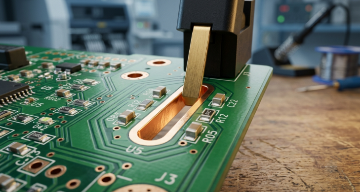
The most important advantage that a slot hole has is its mechanical strength. A flat or blade lead sitting in an elongated slot provides a greater solder contact surface than a round pin in a round hole. This means that the joints are tougher and can better withstand vibration and mechanical shock. This is very important for heavy load items such as transformers, large relays, or power connectors. A slotted hole distributes mounting load over the length of the hole rather than a point, to reduce the stress at a point. This leads to reduced cracking of joints and extended service life in harsh environments. Slots also allow for a more forgiving assembly. The opening is longer than it is wide, and parts can still drop in place without any trouble, given slight tolerances for the lead position. This minimizes rework and increases first-pass yield on the assembly line.
Better Thermal Management and Assembly Flexibility
Slot holes can also assist you in controlling heat and mechanical tension. The plated slot can be designed to hold more copper around a large pin in high-current areas, which helps to handle more current and spread the heat as opposed to a tight round hole. That is why power boards depend on slots for connectors to pass a number of amps. Slots also provide additional flexibility in assembly, not just their thermal properties.
- Alignment tolerance: Slightly oversized slots provide self-alignment of boards or brackets when installing.
- Stress relief: Elongated openings relieve stresses from expansion between materials of different thermal coefficients.
- Space savings: One slot can take the place of a group of round holes, thereby saving space for routing.
All of these benefits make slotted holes a common feature of robust, reliability-seeking designs, rather than a specialized solution.
Critical Design Considerations for Slot Holes
Size, Aspect Ratio, and Placement Guidelines
Each slot has a width and a length, and the ratio between the two, combined with the thickness of the board, defines manufacturability. If your slot is extremely thin, but your board is extremely thick, it will be difficult to drill and plate. A sensible aspect ratio prevents loss of yield. Here are some placement and sizing habits to get clean results:
- Maintain the width-to-thickness ratio: When using plated slots, do not go below a width of approximately 1/10 the thickness of the board for the width of the slot for reliable plating.
- Maintain clearance from edge: Ensure that sufficient clearance is kept between a slot and the outline of the board to prevent breakout when routing.
- Separate slots: Make sure there is sufficient web space between slots to prevent substrate cracking.
- Rounded ends: Oval (rounded-end) slots run more smoothly and reliably than sharp rectangular ends.
Minimum Slot Hole Size and Tolerance Requirements
The most critical specification to get right is the slot size. There is a minimum slot width that manufacturers establish depending on their tooling; otherwise, the drill bits may become broken, or there may not be enough plating. As a rule of thumb, plated slots start off around .5mm wide, while non-plated slots are usually at least 1.0mm wide, since they are routed with a larger bit. The tolerances are different for the two types of slots, and understanding them will enable you to dimension the parts properly. Typical values are provided in the table below, which can be used in design.
| Parameter | Plated Slot (PTH) | Non-Plated Slot (NPTH) |
|---|---|---|
| Minimum Width | 0.5 mm | 1.0 mm |
| Typical Tolerance | ±0.10 mm | ±0.10 to ±0.15 mm |
| Wall Finish | Copper-plated | Bare substrate |
| Primary Use | Electrical + mechanical | Mechanical only |
Make sure to always use these tolerances in conjunction with your component footprint clearances. The footprint of a pin requiring a 0.6 mm slot should readily accommodate a slot machined to any point within the tolerance band of the pin.
Interaction with Copper, Solder Mask, and Board Edge
Slots always exist in conjunction with copper, solder mask, and board outlines. If you need to plate a slot, offer the plated shop an annulus (ring) of copper all the way around the slot opening, just like a round hole. Not enough annular ring is one of the most common causes of breakout of plating on slots. Solder mask is not to be overlooked. Make sure that your mask opening is big enough to clear the plated pad, but not to expose any bare copper that you don't need along the board. If the slots are not plated, pull the copper back from the edge of the slots so that the router does not smear or short any conductor. Lastly, be aware of the edge of the board. Having a slot too near the outline can reduce the strength of a panel or cause it to break through during depaneling. Slots are kept a safe distance from the edge, which helps to ensure that both the feature and the surrounding laminate are safe.
Manufacturing Challenges and Precision Solutions
Even if the dimensions of the slot are correct, if the process is not controlled, it may go wrong on the shop floor. Knowing how slots are cut will aid you in designing it correctly and even communicating clearly with your fabricator.
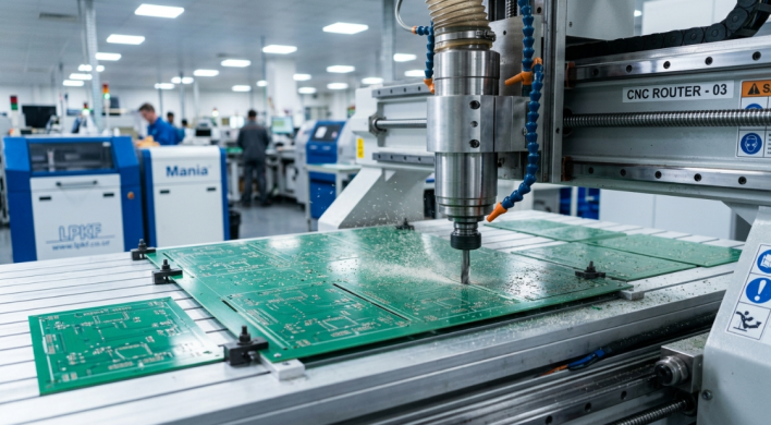
Drilling vs Routing Techniques for Slot Holes
There are two basic types of slot, and both are appropriate for different geometries. By knowing which one your manufacturer will use, you can get a good idea of what kind of quality can be obtained.
- Drilling (drill-walking): A series of overlapping round holes is punched along the length of the slot, and the scalloped wall is cleaned up. This method is quick and is effective in shorter plated slots.
- Routing/milling: A programmed path is carved by a rotating router bit to create a smooth-walled slot. Cleaner walls are produced in routing, and it is more suitable for longer and non-plated slots.
Generally, short plated slots are drilled and then plated, whereas longer or wider slots are routed. Many fabricators do both to achieve a compromise between speed and quality of finish - drill ends and route middle.
Controlling Quality, Burrs, and Dimensional Accuracy
Burrs, rough walls, and dimensional drift are the enemies of a good slot. Burrs are small raised edges that result from cutting, and that may affect the fit of components or cause shorts. They are kept under control by controlled feed rates, sharp tooling, and deburring steps. Tool wear, registration, and material stability are critical to dimensional accuracy. Good shops carefully check drill and router bits and change them when they become worn enough to cause slots to become out of tolerance. They are also used to compensate for the expansion of the material to ensure that the final product is within the limits of the slot. In plated slots, plating uniformity along the slot wall is important. Since the perimeter of a slot is longer than that of a round hole, it is harder to maintain an even thickness of copper without paying attention to chemistry and current distribution. The key to a successful slot that can withstand thermal cycling is consistent plating.
JLCPCB's Advanced Capabilities in Slot Hole Processing
High-Precision Equipment and Strict Process Control
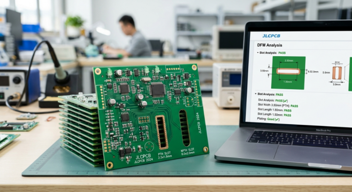
JLCPCB has CNC Routers and precision drills with tolerances optimized. Board outline and slot routing are usually within ±0.2 mm, and controlled hole tolerances ensure that plated and non-plated slots are within specification. This accuracy translates to the slot you draw and the slot you get being very close. The hardware is supported by strict process control. Defects are prevented prior to shipment through tool monitoring, automated optical inspection, and electrical testing. This means uniformity of wall quality, freedom from burrs, and even plating coverage in slots.
Comprehensive DFM Feedback for Slot Hole Designs
Nothing is more valuable than a manufacturer can do than alert you to a problem before production begins. When you upload your files, JLCPCB's automated DFM analysis automatically checks your slot dimensions, spacing, and clearances. If the slot is too narrow, too close to the edge, or the annular ring is not complete enough, you are flagged early. This feedback loop is a real-time and cost saver. You don't have to intervene after the plating job, but rather during the quoting phase. That responsiveness helps keep projects on schedule, especially for engineers who need to make rapid iterations.
Consistent Quality from Prototype to Volume Production
A slot that performs in a prototype should perform exactly the same in a production run of thousands. That is precisely what JLCPCB's process was designed to achieve, and that is why the tolerances that you validated on your $2 prototype order are carried over for volume manufacturing. Slots aren't re-qualified with each increase. When you're ready to implement these slot design guidelines, JLCPCB's instant quote and DFM (Design for Manufacture) tools can help you prototype your slotted-hole design, test for fit, and confidently enter production.
FAQ about Slot Holes in PCBs
Q: What is a slot hole in a PCB?
A slot hole is an elongated, oval, or rectangular opening in a printed circuit board whose length is greater than its width. It is used to fit flat or blade-style leads, mount hardware, or provide mechanical and thermal relief that a round hole cannot offer.
Q:What is the minimum slot hole size I can design?
As a general benchmark, plated slots start around 0.5 mm in width, while non-plated slots typically require about 1.0 mm because they are routed with a larger bit. Always confirm the exact minimum with your manufacturer, since it depends on their tooling and board thickness.
Q: What is the difference between a plated and a non-plated slot?
A plated (PTH) slot has copper plating on its walls, providing both electrical connection between layers and mechanical strength. A non-plated (NPTH) slot has bare substrate walls and serves purely mechanical purposes such as mounting or alignment.
Q:Q: How much tolerance should I allow for a slot hole?
Plated slots typically hold about ±0.10 mm, while non-plated slots are closer to ±0.10 to ±0.15 mm. Add this tolerance to your footprint clearances so the component still fits when the slot lands anywhere within its allowed range.
Conclusion
Although a slot hole is a tiny detail, it has a significant impact on the reliability of your board. The slotted hole addresses issues that round holes can't solve; it can be used to anchor heavy connectors, to distribute heat, and to absorb mechanical stresses. The important thing is to respect the fundamentals: correct slot hole size, sensible aspect ratios, adequate annular ring, and clean edge clearance.
Well-designed slots will continue to become more and more significant as electronics continue to trend towards higher power and harsher environments. Get the design rules right now, and you will not find yourself in the position of having designs rejected by DFM or failing in the field due to a lack of preparation. Combine that expertise with a manufacturer such as JLCPCB that has an accurate set of manufacturing equipment, honest DFM feedback, and has worked hard to ensure that the production quality of the slotted-hole begins from the prototype stage, and you will achieve the ideal effect of the slotted-hole design every time.

Keep Learning
Understanding SMT PCB Boards Technology: An Essential Component of Modern Electronics
Surface Mount Technology (SMT) has changed manufacturing of modern electronics. It has made designs and assembly methods more efficient. Many modern electronics depend on SMT PCB boards, which make it possible for circuit designs to be small and efficient. This is what today's technology needs. This article discuss about many types of SMT PCB boards, their uses, and the best methods for designing and assembling them. 1. What is an SMT PCB Board? Printed circuit boards called SMT PCB boards, use surfac......
How to Choose the Right Prepreg Material for Reliable Multilayer PCB
Have you ever wondered what makes all those copper layers stick to a cross-section of a multilayer PCB? Prepreg material is the answer, and it is of much more importance than most engineers think it is. Choose the prepreg selection wrong, and you are predetermined to delamination, impedance drift, and long-term reliability problems. Prepreg is not only glue. It is a designed composite that determines your dielectric separation, dictates your impedance, affects signal loss, and determines your board be......
Via Filling Explained: Key Techniques, Benefits, and Solutions for High-Performance PCBs
Key Takeaways Via filling completely fills plated through-holes and microvias with epoxy or conductive copper paste, followed by planarization and copper capping (POFV). It eliminates voids, solder wicking, and thermal/mechanical issues while enabling reliable via-in-pad designs. Benefits include superior heat dissipation (up to 8 W/m·K), better signal integrity, higher mechanical strength, and improved assembly yields. JLCPCB provides free non-conductive filling + POFV on 6+ layer boards. Ideal for H......
How Fiducial Markers Guarantee Perfect Alignment in Professional PCB Fabrication
Today, the most sophisticated pick-and-place machine can place a 0.5 mm pitch QFP on its footprint, board after board, thousands of times, and never miss. It is not only a matter of expensive cameras or high-quality servos, but it begins with a little, very small copper dot, simply hanging there in the corner of your PCB. That dot represents a fiducial marker, and without it, even the smoothest SMT line would be laying components in the dark. The unrecognized heroes of automated assembly are the fiduc......
Technical Guidance: Character Design Specifications
To facilitate component assembly, future maintenance, and traceability of PCB manufacturing information (such as manufacturer, production date, batch number, etc.), various character markings are typically silk-screened onto the PCB. These include component designators, polarity marks, test point labels, company logos, and production traceability information. Traditional PCB character silk-screening uses the screen printing process, hence the term “silk-screen characters.” High-definition characters a......
Step-by-Step Guide to the Printed Circuit Board Manufacturing Process
Key Takeaways Core Role: PCBs provide the physical foundation and electrical connections for modern electronics. Multi-Step Process: Manufacturing spans design imaging, substrate creation, inner/outer layer etching, lamination, and surface finishing. Precision & Quality Control: Features micro-drilling (down to 100 µm) for layer connectivity, Automated Optical Inspection (AOI), and final electrical testing. Protection & Finish: Solder masks and surface finishes (e.g., ENIG, HASL) protect copper traces......