
Understanding PCB Thermal Conductivity : Material Choices, Calculation Methods, and High-Performance Solutions
8 min
- Fundamentals of Thermal Conductivity in PCB Materials
- Common PCB Materials and Their Thermal Conductivity Values
- Calculating Effective Thermal Conductivity of PCBs
- Strategies to Achieve High Thermal Conductivity in PCBs
- Practical Applications and Performance Considerations
- Frequently Asked Questions (FAQ)
When it comes to compact electronics, the challenge is power consumption, and thermal issues arise due to that. A PCB can pass DRC checks, SI simulations, and even functional testing, yet it may fail miserably in the field due to poor heat management. PCB thermal conductivity is no longer optional for electronics designers; it has become the core consideration in modern designs. As the component sizes shrink, the thermal margins disappear. When designing a PCB with complexities and compact assembly, one should be aware of the right thermal conductivity of PCB material.
We will see in this article how to calculate PCB effective thermal conductivity, which can mean the difference between a robust product and a costly redesign. This article provides a practical and engineer-friendly deep dive into PCB thermal conductivity. We will cover some proposed materials, calculation methods, and proven strategies to design high thermal conductivity PCBs.
Fundamentals of Thermal Conductivity in PCB Materials
Defining Thermal Conductivity and Its Role in Heat Transfer
Thermal conductivity k is measured in W/mK and defines how efficiently a material transfers heat to the surroundings. In the PCB design, the k factor governs how quickly heat generated by components moves away from the junction. And cools down the component by spreading across the board. In practical terms:
- Low thermal conductivity PCB: The heat accumulates near components
- Thermally conductive PCB: The heat is spread to copper planes, vias & heat sinks
Manufacturers are focused on the PCB substrates that are more optimised for electrical insulation, not for heat flow. Standard epoxy laminates used in PCBs behave more like thermal insulators than conductors. That’s why thermal design must compensate through layout and material selection. In the PCB design, the electric current flows and is guided through the low impedance copper paths. In the same way, the heat is also guided through copper, but there is a dielectric in the board that sits in the middle and restricts the heat flow.
In-Plane vs Through-Plane Conductivity Differences
One of the most misunderstood aspects of PCB thermal behaviour is directional conductivity. PCBs exhibit anisotropic thermal conductivity, which means the heat flows based on the direction. We might call it a vector quantity.
In-plane thermal conductivity:
- Heat spreads laterally along the PCB surface
- Dominated by copper planes and trace density
- Typically higher than through-plane values
Through-plane thermal conductivity:
- Heat flows vertically through the PCB thickness
- Dominated by dielectric materials
- Usually, the thermal bottleneck
Here we have an example of an FR4 board, which comes with an in-plane thermal conductivity of 0.3 W/mK and a through-plane conductivity of around arounof0.25 W/mK. Usually, the copper is able to dissipate at 400 W/mK, but see how it decreases when it actually comes to a PCB stackup. This massive mismatch explains why copper pours dramatically improve heat spreading. However, we can implement thermal vias and increase a bit of copper thickness to solve some of the heating issues.
Impact on Component Temperature and Board Reliability
Thermal conductivity directly affects the:
- Junction temperature
- Mean time to failure
- Solder joint reliability
- PCB material stability
A widely accepted rule of thumb is that every 10 °C increase in junction temperature halves semiconductor lifetime. Poor thermal conductivity can cause:
- Delamination between PCB layers
- Solder fatigue and cracking
- LED lumen depreciation
- Premature component ageing
In short, thermal design determines whether your PCB survives the lab or the customer.
Common PCB Materials and Their Thermal Conductivity Values
Standard FR4 and Low-Cost Laminates
FR4 remains the default choice for most designs due to its low cost and excellent manufacturability. It comes with typical properties:
- Thermal conductivity: 0.25–0.35 W/m·K
- Electrical insulation: Excellent
- Cost: Low
- Availability: Very high
From a thermal standpoint, FR4 is mediocre at best. It traps heat efficiently, which is great for insulation but terrible for power electronics. Because the heat dissipation and thermal conductivity fail when we go to denser designs. Somehow, the industry manages to do a lot of FR4 and its different variants. Originally, the FR4 was proposed because it can not catch fire and hence it is safe. By the way, the FR4 works well for low-power digital circuits and control logic boards.
Enhanced Materials with Fillers or High-Tg Resins
To bridge the gap between cost and performance, manufacturers offer thermally enhanced laminates. This is basically a modification of epoxy systems with ceramic. Typical thermal conductivity range: 0.6–2.5 W/m·K
Although we got several advantages by doing so, it improves heat spreading. We got better high-temperature stability with minimal process changes. These materials enable thermally conductive PCBs without requiring metal cores, which makes them ideal for medium-power DC-DC converters and compact industrial electronics. Think of them as FR4 that finally decided to take thermal management seriously.
Metal-Core and Ceramic-Based Options for Superior Heat Dissipation
When thermal performance becomes non-negotiable, and price is not a concern anymore. Jump to metal-core PCBs (MCPCB) and ceramic substrates. In the metal-core PCB, we have options of an aluminium or copper base. They provide:
- Thin dielectric isolation layer
- Excellent heat spreading
- Common in LED lighting and power modules
Ceramic PCBs like Al₂O₃, AlN comes with thermal conductivity: 20–170 W/m·K and provide:
- Exceptional thermal stability
- Electrically insulating
- Higher cost and processing complexity
These materials enable true high thermal conductivity PCB designs. They are used where the conventional laminates fail.
Calculating Effective Thermal Conductivity of PCBs
Volume-Weighted Average Models for Multi-Layer Boards
Real PCBs consist of multiple materials stacked together. To estimate PCB effective thermal conductivity, engineers often use a volume-weighted average function mentioned below:
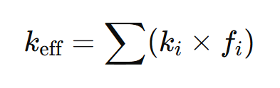
Where:
- (ki) = thermal conductivity of each layer
- (fi) = volume fraction of each layer
This method provides quick, early-stage estimates and Insight into material influence. We have directional conductivity approximations, which are helpful for simulations.
Accounting for Copper Planes, Vias, and Layer Stackup
Copper dominates thermal behavior even in small quantities. We can use some strategies with copper to make a better design. By changing the copper plane thickness and coverage in the high-density sections. By inserting thermal via density and fill type. Thermal vias act as vertical heat pipes. For example, the heat profile of filled vias > plated vias > empty vias.The larger the diameter of the via, the better the overall conduction. Ignoring vias when you calculate PCB thermal conductivity is equivalent to ignoring resistors in a circuit analysis.
Tools and Formulas for Quick Estimates
Engineers typically rely on:
- Spreadsheet-based resistance models
- 1D thermal resistance networks
- ECAD thermal estimators
- Manufacturer design guides
Strategies to Achieve High Thermal Conductivity in PCBs
Incorporating Thermal Vias and Copper Planes
Layout-level thermal optimisation should always come first. Some Best practices can be:
- Using dense via arrays beneath heat sources
- Adding Large and uninterrupted copper pours
- Using thick internal copper planes
A well-designed via matrix can outperform expensive materials at a fraction of the cost.
Selecting Thermally Conductive Substrates and Fillers
Material selection should match power density. The general guidelines are that if the design is under 1watt and goes up to 2-3W, then use standard FR4. If the circuit takes 1–5 W, use enhanced epoxy laminates. Switch to MCPCB or ceramic for higher wattage than this. Choosing the wrong thermal conductivity of PCB material often leads to late-stage redesigns.
Practical Applications and Performance Considerations
Power Electronics and LED Lighting Requirements
Power electronics demand aggressive thermal management. Because now we are pushing more power, this power is usually either converted to some other form or transformed into heat, as per the efficiency of design. High thermal conductivity PCBs are critical for:
- MOSFET and IGBT modules
- High-current regulators
- High-brightness LEDs
In LED systems, junction temperature directly affects the colour and brightness of the product. If not taken care of, the overall lifetime is reduced. Hence, the poor thermal design might dim your product’s future.
High-Speed and RF Designs with Thermal Constraints
RF and high-speed materials are preferred because they come with controlled impedance material and low Dk. Unfortunately, these materials often have modest thermal conductivity. Hence, there should be a proper choice between high-speed and power electronics boards. Although with the above given techniques and tips, we engineers can carefully balance:
- Signal integrity
- Thermal dissipation
- Mechanical stability
Thermal planning must start at stackup definition, before placement, not after routing.
Trade-Offs Between Thermal Performance, Cost, and Manufacturability

The best thermal design is useless if it cannot be manufactured or afforded. Rather than jumping over changing material and all, first solve the thermal problems at the layout end. After making the best possible layout, if the thermal profile still remains the same, we can think of a material upgrade. For better design, engage engineers from manufacturers like JLCPCB early in the design phase. In thermal engineering is not always about using extremes; it is about optimisation.

Frequently Asked Questions (FAQ)
What is a high thermal conductivity PCB?
A PCB designed using conductive materials, copper structures, and vias to efficiently remove heat from components.
How do I calculate PCB's effective thermal conductivity?
Using volume-weighted material models combined with copper and via contributions.
Is FR4 suitable for power electronics?
Only for low-power applications. Medium to high power typically requires enhanced laminates or metal cores.
Are metal-core PCBs expensive?
More expensive than FR4 but cheaper than field failures and recalls.
Keep Learning
Your Ultimate Guide to PCB Rulers
In the world of PCB design and manufacturing, having the right tools is crucial for achieving accuracy and precision. One such tool that has gained popularity among professionals and hobbyists is the PCB ruler. This specialized measuring tool is designed to provide accurate measurements, reference information, and component footprints, assisting designers, engineers, technicians, and assemblers in various stages of PCB development. In this guide, we'll explore what a PCB ruler is, the features and mea......
Understanding the Materials Used in PCBs: Selection, Types, and Importance
Key Takeaways FR-4 is the go-to material for most cost-effective and reliable PCBs. Use Rogers for high-frequency and RF applications to reduce signal loss. Higher copper weight (2oz) improves current and heat handling. Choose High-Tg substrates for better thermal stability in multilayer boards. Green LPI soldermask offers the best balance of performance and inspection. Printed circuit boards (PCBs) are an essential component of modern electronics. These boards connect and support electronic component......
How to Select Tg of PCB ?
What is the Tg of PCB? In PCB manufacturing, "Tg" stands for Glass Transition Temperature. It is the temperature at which the PCB substrate material transitions from a rigid, glassy state to a soft, rubbery state. PCBs are flame-retardant (UL94 V-0) and do not burn easily; instead, they soften above Tg. The Critical Correlation Between Tg and Z-Axis CTE (Coefficient of Thermal Expansion) When the temperature exceeds the Tg point, the PCB substrate material (such as standard FR-4) undergoes a physical ......
How to Choose the Thickness of PCB
First, In the world of electronic products, the PCB is often referred to as the "heart" of the device. It interconnects all components, making board thickness one of the most important parameters. Choosing the right PCB thickness directly affects the electrical performance, mechanical stability, thermal management, and long-term reliability of the final electronic product. The process of selecting PCB thickness is influenced by various factors, such as product application scenarios, board material, an......
PCB Copper Pour Basics
What is Copper Pour in PCB Design? Copper pour refers to the technique of filling unused areas of a PCB's copper layers with solid copper planes. These planes are connected to power or ground nets, creating a continuous conductive path. Copper pour is typically used in the power and ground planes, as well as in signal layers for specific purposes. Purpose and Benefits of Copper Pour: Copper pour is primarily used to fill unused areas on PCB copper layers with solid (or hatched) copper connected to pow......
How to Prevent Solder Bridges for Superior PCB Quality and Reliability
Key Takeaways Solder bridges are a leading cause of SMT failures on fine-pitch components. Prevent them with proper solder mask dams (0.075–0.1mm), optimized stencil design, and controlled reflow profiles. Combine good DFM practices with AOI + X-ray inspection for maximum reliability. Professional manufacturing and early DFM review significantly boost first-pass yield and reduce costly rework. You have experienced the post-reflow sadness and eyed the board that failed on the first reflow, if you have ......