Moisture Sensitivity Level (MSL): Baking Guide
15 min
- Quick Answer: What Is Moisture Sensitivity Level (MSL)?
- Why Moisture Matters: The Popcorn Effect
- MSL Levels and Floor Life
- J-STD-020 vs J-STD-033: Who Owns What
- How to Know a Component’s MSL Level
- The Floor-Life Clock: When You Must Bake
- How to Bake Components Before Reflow
- Dry Storage: Preventing the Problem
- Where This Fits in the SMT Flow
- Common Moisture-Related Reflow Defects
- FAQs About Moisture Sensitivity Level (MSL) and Baking
- Conclusion: Moisture Sensitivity Level — Bake When You Must
Key Takeaways
Moisture Sensitivity Level (MSL) is a 1-6 classification under IPC/JEDEC J-STD-020 that indicates how quickly a non-hermetic surface-mount package can absorb enough moisture to become vulnerable during reflow.
MSL 1 has unlimited floor life at its reference condition, while MSL 6 requires baking before use and reflow within the time printed on the caution label.
The floor-life clock begins when the moisture barrier bag is opened and exposure to factory air starts.
Baking according to IPC/JEDEC J-STD-033 removes absorbed moisture; compliant dry storage helps prevent additional exposure.
Lead-free processing makes moisture control more important because package classification temperatures can reach 245-260 °C.
You open a reel of MSL 3 microcontrollers, use only part of it, and leave the remainder on the production floor. Two weeks later, the parts go through reflow and the finished boards pass inspection. The problem may not appear until months later, when hidden package damage turns into an intermittent field failure.
This guide explains moisture sensitivity level (MSL), floor life, when baking components before reflow is necessary, and how to dry moisture-sensitive devices without damaging their packaging. It focuses on moisture control before soldering. For the temperature curve itself, use the reflow soldering guide rather than treating MSL handling as a substitute for a validated reflow profile.
Quick Answer: What Is Moisture Sensitivity Level (MSL)?
Moisture Sensitivity Level (MSL) is a 1-6 classification used under IPC/JEDEC J-STD-020 to indicate how quickly a non-hermetic surface-mount package can absorb enough moisture to become vulnerable during reflow. Each level defines a floor life: the allowable time between opening the dry pack and soldering under specified factory conditions.
Why Moisture Matters: The Popcorn Effect
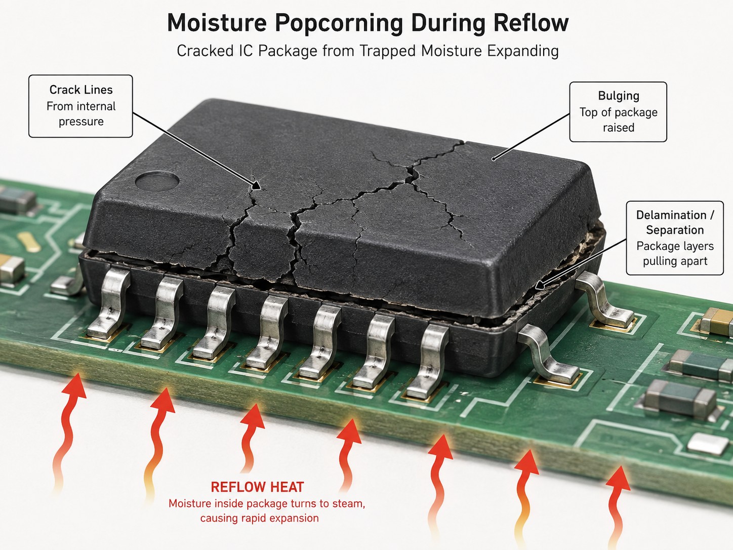
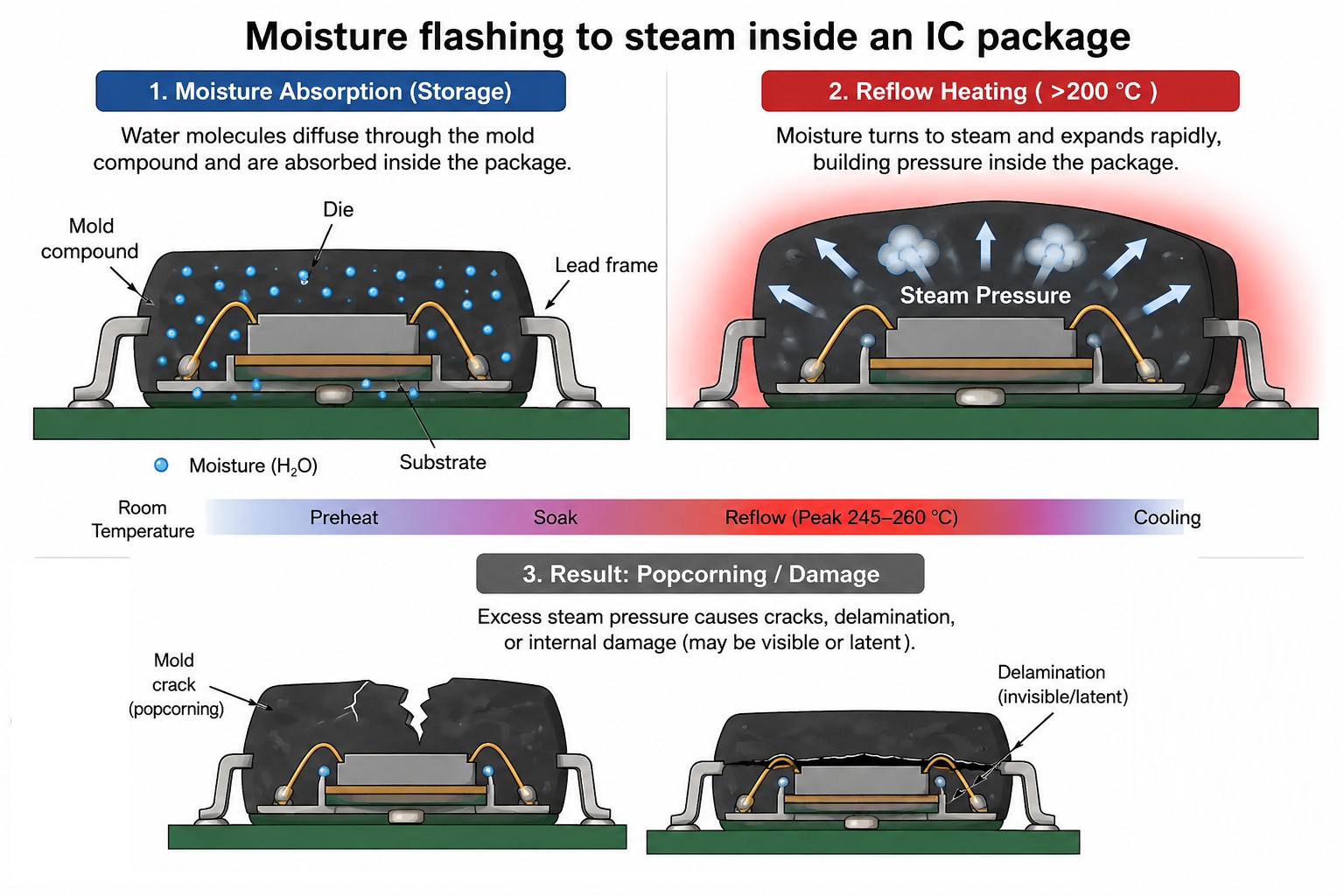
Plastic IC packages are not completely moisture-tight. Their epoxy mold compounds can absorb water vapor from the surrounding air. According to the moisture-sensitivity principles defined in IPC/JEDEC J-STD-020, this absorbed moisture becomes critical when the component is exposed to reflow temperatures above 200 °C.
During reflow, trapped moisture rapidly turns into vapor and expands inside the package. The resulting pressure stresses internal interfaces such as the die-to-substrate and substrate-to-mold-compound boundaries. If the pressure becomes high enough, the package may bulge or crack — a failure commonly known as the popcorn effect. Not every failure is visible. Moisture can also cause internal delamination, micro-cracks, or separation around the die and substrate while the package still looks normal from the outside. These defects may survive initial inspection and electrical testing but later cause reliability problems during thermal cycling, vibration, or normal field operation.
Moisture exposure can also contribute to oxidation, voiding, and reduced solderability. In fine-pitch packages such as BGA and QFN devices, prolonged moisture exposure can increase the risk of corrosion around sensitive internal or termination areas, making good storage and floor-life control especially important. The problem became more significant with lead-free assembly. Traditional leaded processes typically peaked around 220–230 °C, while many lead-free reflow profiles reach approximately 245–260 °C. The higher temperature creates more rapid vapor expansion and greater internal stress, which is why some components that were less sensitive under older leaded processes require stricter MSL control today. The important point is that moisture damage can be latent. A board may pass AOI and functional testing immediately after assembly but fail weeks or months later because of hidden delamination or cracking.
MSL Levels and Floor Life
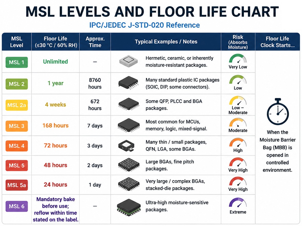
The MSL levels chart below summarizes the standard floor-life limits used for moisture-sensitive surface-mount devices. Unless otherwise stated, the reference condition is no more than 30 °C and 60% RH. MSL 1 uses the less restrictive 85% RH reference condition.
| MSL Level | Floor Life (≤30 °C / 60% RH) | Notes / Typical Packages | |
|---|---|---|---|
| MSL 1 | Unlimited | Moisture-resistant packages; many hermetic/ceramic devices are not MSL-limited in the same way. | |
| MSL 2 | 1 year | Many standard plastic packages. | |
| MSL 2a | 4 weeks | Intermediate handling tier. | |
| MSL 3 | 168 hours (7 days) | Common for MCUs, memory, logic, BGAs and QFNs. | |
| MSL 4 | 72 hours | Often seen on thinner or more moisture-sensitive packages. | |
| MSL 5 | 48 hours | Tight floor-life control required. | |
| MSL 5a | 24 hours | Very short allowable factory exposure. | |
| MSL 6 | Mandatory bake before use | Reflow within the time stated on the moisture-sensitivity label. |
An MSL number does not describe device quality. It describes how carefully the package must be handled once it leaves dry storage. MSL 3, for example, allows 168 hours of cumulative floor exposure at the reference condition, while MSL 5a allows only 24 hours.
Moisture diffusion is strongly influenced by package construction and thickness. Diffusion time scales roughly with the square of diffusion distance, so package geometry affects how quickly moisture can reach critical internal regions. The ‘a’ ratings provide intermediate handling tiers between the main MSL levels.
J-STD-020 vs J-STD-033: Who Owns What
IPC/JEDEC J-STD-020 is the classification standard. Component manufacturers use it to expose packages to controlled moisture and reflow stresses and then assign the applicable moisture sensitivity classification. In simple terms, J-STD-020 answers: How moisture-sensitive is this package, and what reflow classification applies?
IPC/JEDEC J-STD-033 is the handling standard. It covers what happens after classification: dry packing, storage, floor-life tracking, humidity control, and drying or baking before assembly. It answers: Now that I know the MSL rating, how should I store and handle the part?
That distinction matters. MSL is also not the same as sealed-bag shelf life. A properly dry-packed component may have a long-sealed storage period, while its floor life can be only a few days after the bag is opened. Many suppliers dry packs specify around 12 months or more of shelf storage under defined conditions, but the package label and current manufacturer instructions take priority.
How to Know a Component’s MSL Level
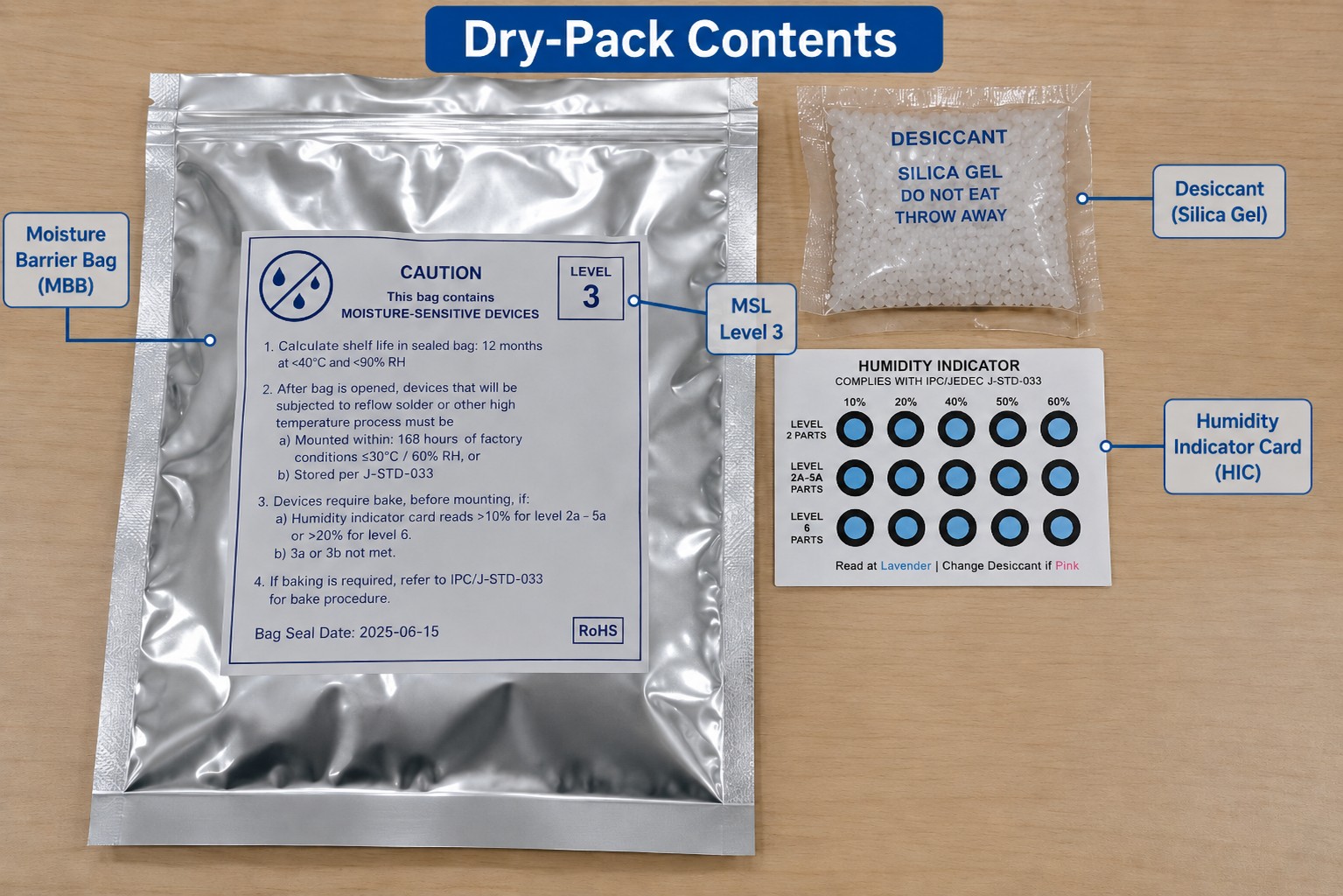
Start with the moisture barrier bag (MBB). The caution label normally identifies the MSL rating, allowable floor life, and relevant reflow information. Major component distributors often expose the same data in their product records, and many semiconductor manufacturers include it in the packaging or quality section of the device documentation.
Inside a proper dry pack you will normally find desiccant and a humidity indicator card (HIC). Check the HIC as soon as the bag is opened. Its color spots indicate whether humidity inside the sealed environment rose above the specified threshold. If the card shows excessive humidity, treat the lot according to the supplier instructions rather than assuming the parts are dry.
If you are outsourcing assembly, review JLCPCB's MSL management guidance to understand how moisture-sensitive parts are handled within its service flow. MSL 1 devices remain the easiest case because their standard floor life is unlimited at the reference condition; higher MSL numbers require progressively tighter control.
The Floor-Life Clock: When You Must Bake
Think of floor life as a cumulative exposure budget, not a one-time countdown that disappears when the shift ends. If an MSL 3 reel is exposed for 40 hours, returned to compliant dry storage, and later exposed again, the previous exposure still matters unless the parts have been dried in a way that legitimately resets their moisture condition.
According to IPC/JEDEC J-STD-033 handling guidance, baking can remove absorbed moisture and restore the component to a dry condition. Storage in a properly resealed MBB with fresh desiccant and a humidity indicator card, or in a dry cabinet at ≤5% RH, can also stop further moisture uptake under compliant handling conditions. A cabinet around 10% RH may slow or extend the exposure period, but it does not provide the same reset condition. Reflow itself should not be treated as a floor-life reset.
Bake when the specified floor life has been exceeded, the HIC indicates excessive moisture, or the exposure history is unknown. MSL 6 is stricter: baking before use is mandatory, and the part must be reflowed within the time stated on its label. Reflow itself does not erase later moisture exposure, so boards awaiting a second high-temperature process should follow the same logic used in mixed-component reflow planning.
How to Bake Components Before Reflow
Baking drives absorbed moisture out of the package before the component is exposed to reflow temperatures. The correct recipe is not one universal ‘24 hours at 125 °C’ rule. Bake time depends on MSL rating, package thickness, how far the floor-life limit was exceeded, carrier type, and the device manufacturer’s temperature limits.
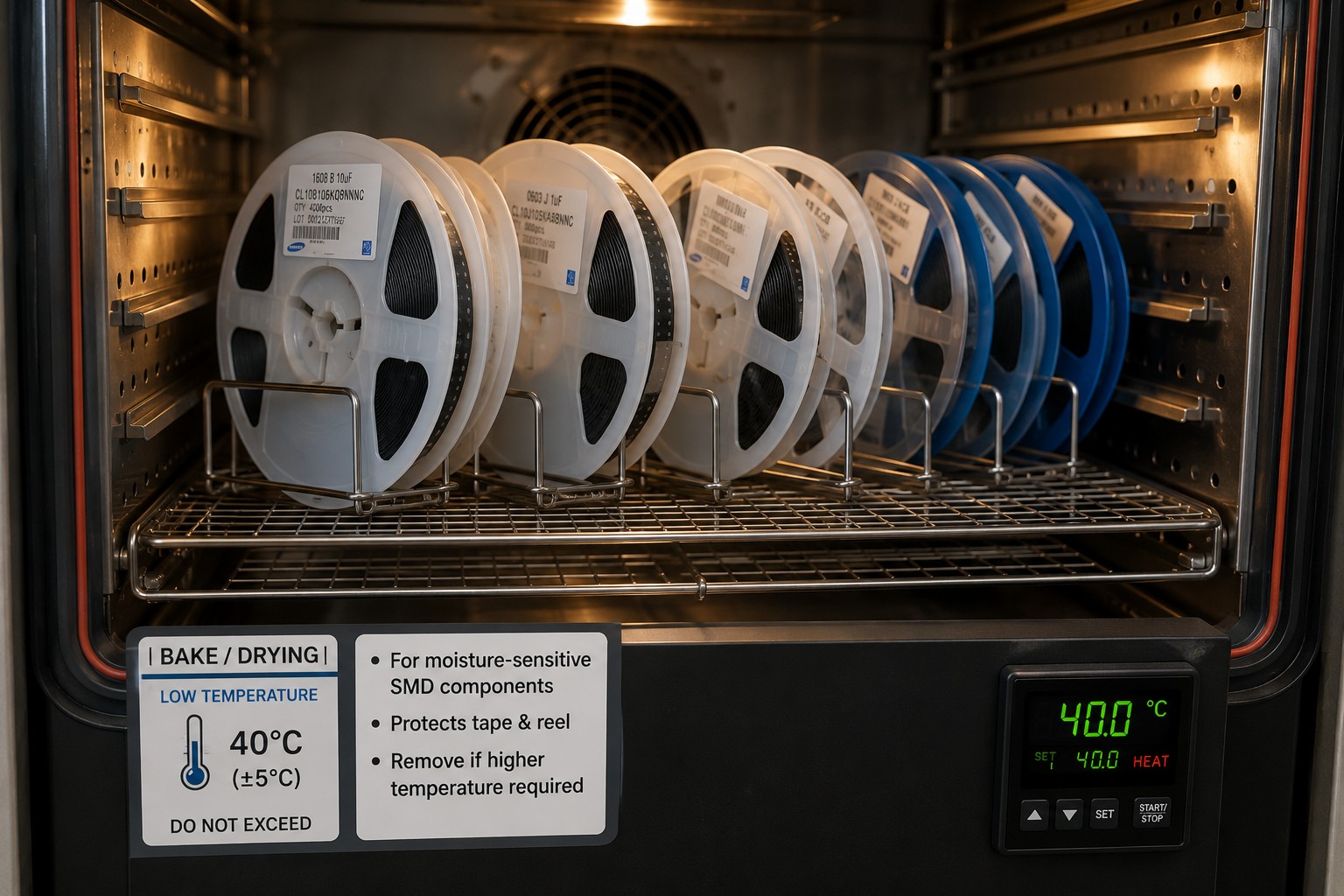
IPC/JEDEC J-STD-033 uses three practical temperature tiers. High-temperature baking is fast, but it demands compatible trays and components. Lower-temperature baking protects tape-and-reel materials and heat-sensitive devices, but drying takes much longer.
| Bake Temperature | Best For | Trade-Off |
|---|---|---|
| 125 °C | Packages and high-temperature carriers qualified for it | Fastest moisture removal; unsuitable for standard tape/reel and some sensitive devices. |
| 90 °C | Moderate-temperature drying where 125 °C is undesirable | Gentler, but significantly longer drying time. |
| 40 °C | Sensitive parts and standard tape/reel carriers | Carrier-friendly, but often requires days rather than hours. often ~192 h / 8 days |
For example, Texas Instruments AN-2029 handling guidance reproduces J-STD-033-based drying tables and shows that the required time can range from hours to many days depending on package thickness and MSL. Do not copy a bake duration from a different package and assume it applies to yours.
Bare PCBs that have been stored in humid conditions are also sometimes dried before assembly, with shop procedures often using roughly 105-125 °C for 2-6 hours. That is a separate board-level decision: laminate type, surface finish, board construction, and the PCB supplier’s limits take priority over a generic temperature-and-time value.
Baking Do's and Don'ts
- Do not place ordinary tape-and-reel, plastic tubes, or low-temperature trays into a high-temperature bake. Semiconductor handling guidance commonly limits standard carriers to about 40 °C unless they are specifically rated for higher temperature.
- Do not over-bake simply ‘to be safe.’ Repeated high-temperature exposure can accelerate oxidation, reduce lead solderability, or damage temperature-sensitive devices such as LEDs, sensors, MEMS parts, and package-on-package assemblies.
- After baking, either move the parts into assembly promptly or return them to a properly controlled dry environment. Leaving a freshly dried reel on the bench simply starts a new exposure period.
- For repair or rework, do not assume that a soldering iron makes MSL irrelevant. Local heating can still drive moisture-related damage in susceptible packages, so use the component maker’s rework guidance and sound process judgment.
Dry Storage: Preventing the Problem
Good moisture control is easier than repeated baking. For moisture-sensitive parts, compliant storage normally means a properly sealed MBB with fresh desiccant and an HIC, or a controlled low-humidity dry cabinet. Vacuum is useful for packaging, but low internal humidity is the important condition; a bag that is poorly sealed is not protected just because it once contained desiccant.
On the production floor, open MSL >2 material only when it is reasonably close to use. Mark partial reels with the open date and time, or track exposure through an MES or inventory system. If the remaining floor life is known, operators can make a rational decision. If it is unknown, the process immediately becomes more conservative and often ends in an unnecessary bake.
Where This Fits in the SMT Flow
MSL handling sits upstream of paste printing, placement, and reflow. A simple SMT sequence is:
Moisture control (dry storage or bake) → solder paste printing → component placement → reflow → inspection.
The reflow oven is where both process paths meet. Correct moisture control protects packages from internal steam pressure, while a well-designed solder paste stencil controls paste volume so the solder joint can form correctly. The guide to choosing a solder paste stencil covers the printing side of that process; the moisture-control steps should remain focused on the component package itself.
For teams qualifying a stencil supplier, the stencil manufacturing capability overview provides process and manufacturing details without changing the MSL handling rules described above.
Common Moisture-Related Reflow Defects
- Popcorning or package cracking: absorbed moisture expands rapidly during reflow → verify floor-life records and dry the parts according to J-STD-033 before another high-temperature cycle.
- Internal delamination: the same pressure mechanism separates package interfaces without an obvious external crack → prevention is the primary control; acoustic microscopy such as C-SAM is used when internal delamination must be evaluated.
- Head-in-pillow or poor coalescence: moisture exposure may be accompanied by oxidation and unstable wetting conditions → verify storage history, component condition, paste condition, and the validated soak/reflow profile rather than blaming only one variable.
- Weak or voided joints and oxidized terminations: prolonged uncontrolled storage can reduce solderability → use dry storage, clean handling, and timely assembly.
For a broader defect checklist, see how to prevent solder defects during reflow.
FAQs About Moisture Sensitivity Level (MSL) and Baking
Q: Can Components Be Used Without Baking If Floor Life Has Not Expired?
Yes. Properly dry-packed components that remain within their allowable floor life normally do not need a precautionary bake. Check the HIC, confirm that the exposure conditions were controlled, and follow the device label. Unnecessary baking adds thermal history and can reduce solderability after repeated high-temperature cycles. When the moisture history is known and still compliant, using the parts directly is usually the better process.
Q: Can I Put an Open Reel Back in Its Moisture Barrier Bag?
Yes, but resealing is useful only when the bag is restored as a controlled dry environment. Use a suitable MBB, fresh desiccant, an HIC, and a proper heat seal; simply folding or taping the bag closed does not provide the same protection. Also remember that resealing does not automatically erase exposure already accumulated on the factory floor. Keep the exposure record with the reel.
Q: Does a Dry Cabinet Reset MSL Floor Life?
Not automatically. A very low-humidity cabinet is excellent for preventing additional moisture uptake, but whether stored time can be excluded or a floor-life reset is allowed depends on the applicable J-STD-033 procedure and the component’s exposure history. Do not treat a normal 10% RH cabinet as equivalent to a full bake. If a lot has exceeded its allowed floor life, use the specified drying procedure.
Q: Can I Bake SMD Components in Tape and Reel?
Only at a temperature the carrier can safely withstand. Standard tape, reels, and many plastic tubes are low-temperature carriers, and semiconductor handling guidance commonly limits them to about 40 °C baking. Higher-temperature drying may require transferring parts to approved bake trays, which itself introduces handling and ESD risks. Check the packaging specification before placing an entire reel into an oven.
Q: Do Boards Need Moisture Control Before a Second Reflow?
Sometimes. A component can absorb moisture again after the first soldering cycle if the assembly sits in ambient conditions before a second reflow, rework, or other high-temperature process. The risk depends on the package MSL, elapsed time, humidity, and thermal process. For assemblies with sensitive BGAs, QFNs, LEDs, or modules, define an inter-process storage limit instead of assuming first reflow permanently solved moisture risk.
Q: Is Vacuum Sealing Enough for Moisture-Sensitive Components?
No. Vacuum sealing by itself does not prove that the environment is dry. A proper dry pack combines a low-permeability moisture barrier bag, dry desiccant, a humidity indicator card, and a reliable seal. The HIC provides the practical check that the package environment remained within its intended humidity range. A damaged bag or saturated desiccant can leave parts at risk even if the bag looks tightly packed.
Conclusion: Moisture Sensitivity Level — Bake When You Must
Moisture sensitivity level (MSL) tells you how quickly a package can become vulnerable after dry pack is opened. The floor-life clock tells you when action is required, and J-STD-033-based baking provides the recovery path when moisture exposure has gone too far. Good dry storage is even better because it prevents unnecessary bake cycles in the first place.
The practical rule is simple: know the MSL, track the exposure, read the HIC, and bake only when the handling condition requires it. Combined with controlled solder paste printing and a validated reflow process, disciplined moisture handling removes one of the most preventable causes of hidden SMT reliability failures.
Keep Learning
Low-Temperature Solder Paste: A Practical Sn-Bi Guide
Key Takeaways Sn42Bi58 is the mainstream low-temp alloy and melts at 138 C. Typical reflow peak is 165 to 180 C, about 25 to 30 C above the melt. It protects heat-sensitive components and reduces warpage on large, thin boards. It enables step soldering, because 165 to 180 C will not remelt SAC305 joints. Bismuth joints are more brittle than SAC305, so avoid drop-critical products. Never mix Sn-Bi with leaded (Sn-Pb) solder. Bi, Sn and Pb form a ternary eutectic that melts near 95 C. Some parts and som......
Pin-in-Paste: Through-Hole Reflow With a Stencil
Key Takeaways One Reflow Process: Pin-in-paste combines SMT and through-hole soldering into a single reflow pass, eliminating the need for separate wave, selective, or hand-soldering steps when the board has only a few through-hole components. Paste Volume Is Critical: Solder paste is roughly 50% flux by volume, so you need to print about twice the solder volume the finished joint requires. Stencil design—overprint apertures and step-up zones—makes or breaks the process. Target 75% Barrel Fill: Per IP......
Mixed Technology PCB Assembly: Combining SMT and THT on One Board
As technologies become increasingly more complex, the demand for sophisticated printed circuit boards continues to rise. In the electronics industry, the two most prevalent PCB Assembly technologies are SMT and THT, which differ mainly in the manner at which the components are attached. SMT places the components on the surface of the board whereas THT makes use of drilled holes to solder components. While these technologies individually cater to specific applications, advancements in the electronics i......
Moisture Sensitivity Level (MSL): Baking Guide
Key Takeaways Moisture Sensitivity Level (MSL) is a 1-6 classification under IPC/JEDEC J-STD-020 that indicates how quickly a non-hermetic surface-mount package can absorb enough moisture to become vulnerable during reflow. MSL 1 has unlimited floor life at its reference condition, while MSL 6 requires baking before use and reflow within the time printed on the caution label. The floor-life clock begins when the moisture barrier bag is opened and exposure to factory air starts. Baking according to IPC......
Understanding SMT Stencil Printers for Accurate PCB Solder Paste Printing
Stencil printing is a critical process in SMT (Surface Mount Technology) assembly, significantly impacting the quality and reliability of solder joints on PCBs. The crucial machine for implementing this is the SMT Stencil Printer, which applies an appropriate measure of solder paste to each pad of the PCB board before it goes to the placement of components. For those of you looking to work out what a stencil printer is and why it matters in manufacturing, you've come to the right place. This is the ba......
Surface Mount Stencil: A Practical Guide for SMT Printing and Solder Paste Application
It starts with a slim piece of metal, slipped in early during assembly. Before any part lands in place, before heat ever touches the board, that layer shapes the flow. Where the paste spreads comes down to its design. How thick it is, how it's cut - those details decide what sticks and what washes away. For engineers looking for reliable stencils, JLCPCB provides high-precision SMT stencils that integrate seamlessly with PCB production workflows. Down goes solder paste, slipping through narrow cuts in......