PCB Mount Techniques, Methods, and Best Practices
10 min
- Introduction
- Electrical Component Mounting Techniques
- Mechanical PCB Mounting & Hardware Integration
- PCB Design for Manufacturability (DFM) & Mounting
- Balancing Reliability and Cost in PCB Assembly
- Advanced Solutions & Best Practices
- FAQs about PCB Mount Techniques
- Conclusion:
Key Takeaways
- SMT vs. THT: SMT fits micro-packages (down to 01005), while THT provides high mechanical strength for heavy components.
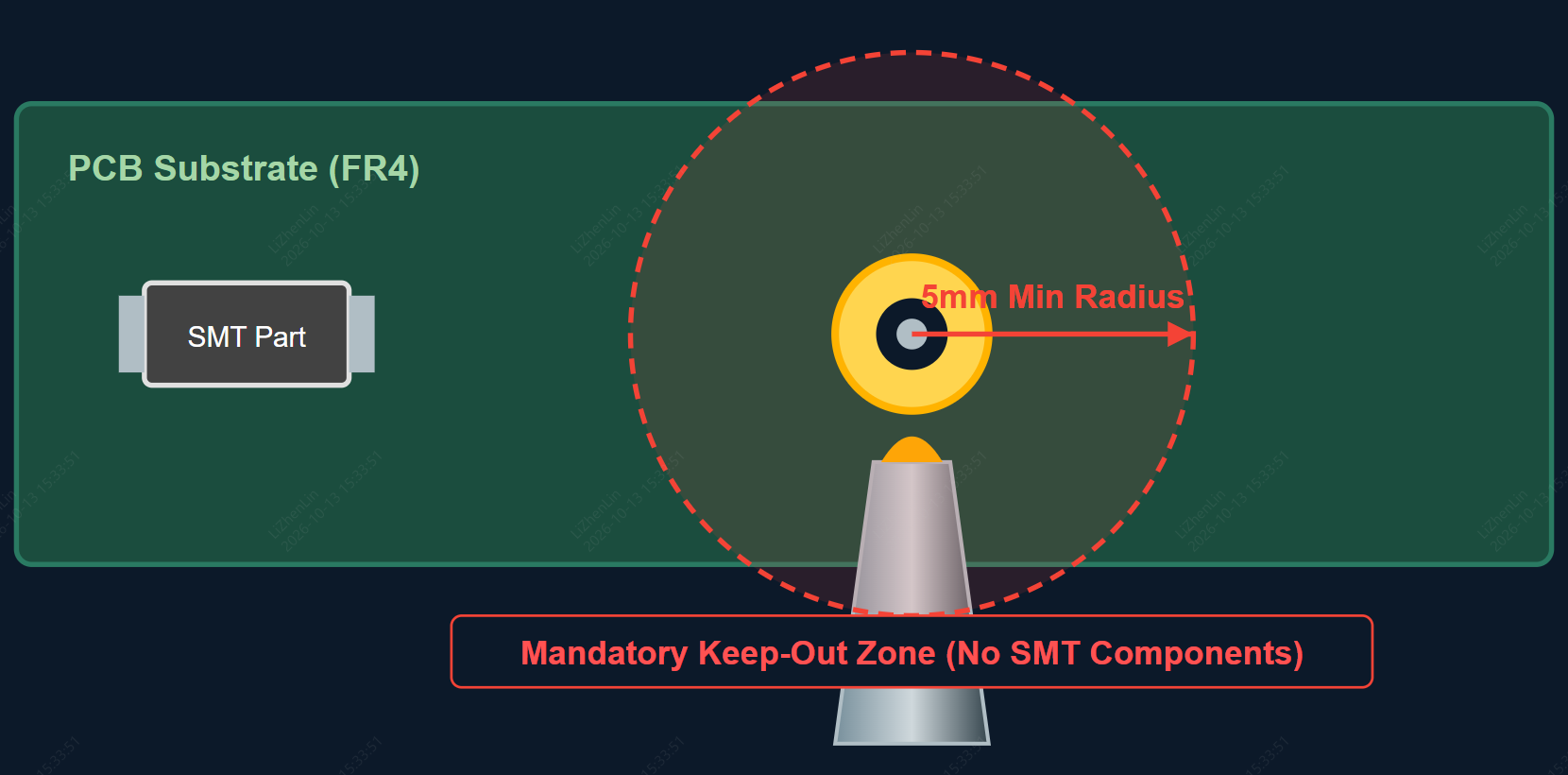
- Selective Wave DFM: Requires a 5mm keep-out zone around THT pads to protect bottom-side SMT parts from thermal shock.
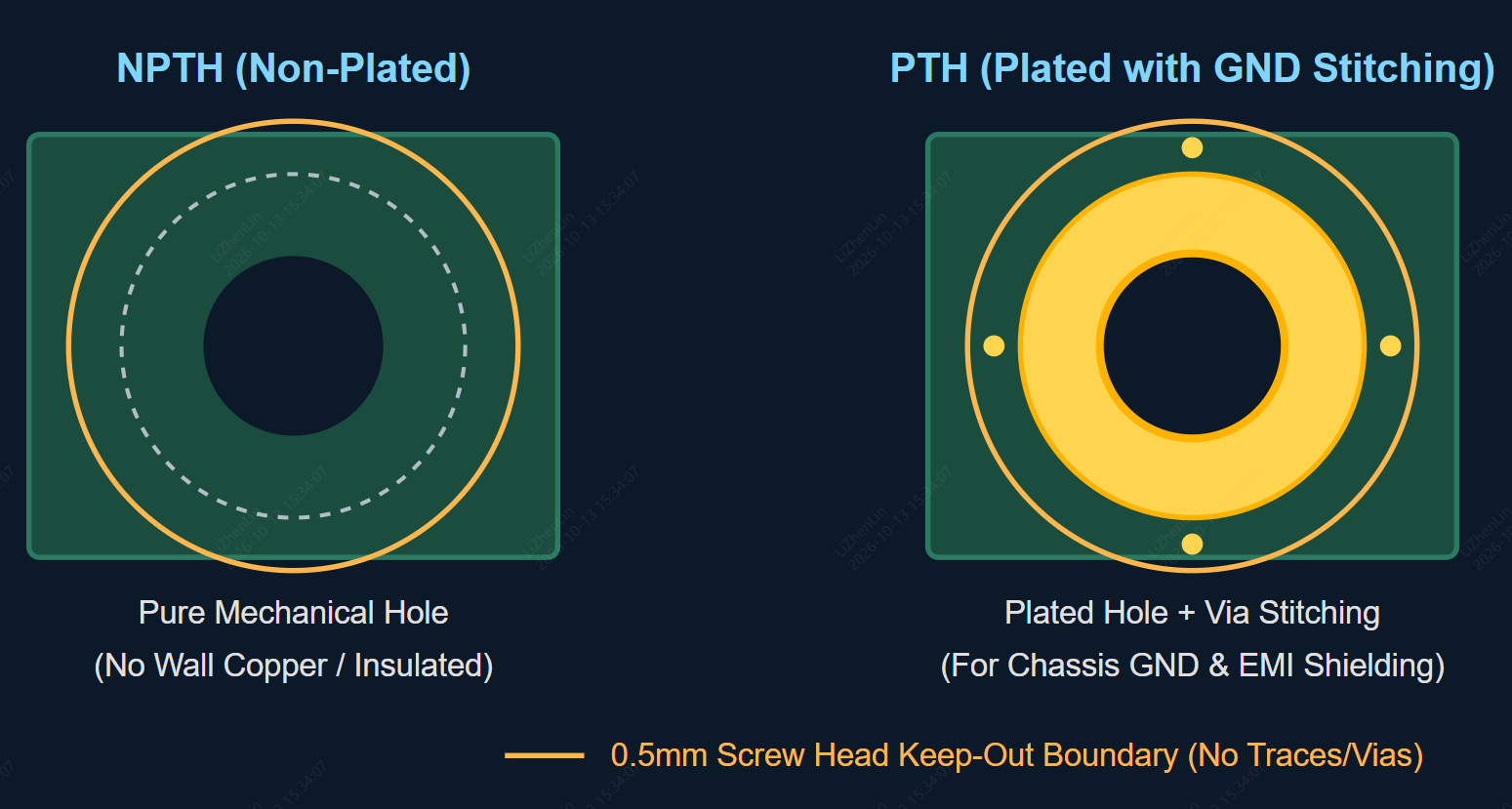
- Mounting Hole Clearance: Keep a 0.5mm minimum clearance around screw heads on NPTH/PTH holes to prevent trace shorts.
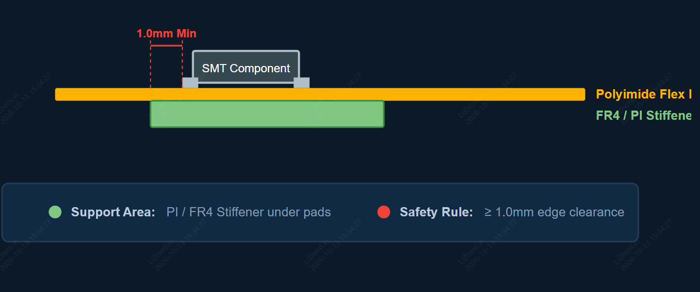
- FPC Stiffeners: Use PI/FR4 stiffeners behind FPC pads with a 1.0mm edge clearance to prevent joint fatigue.
Introduction
In the electronics industry, PCB mounting is a fundamental process that directly affects the assembly, mechanical stability, and thermal efficiency of electronic devices. PCB Mounting refers to the methods used to secure electronic components onto a Printed Circuit Board (PCB) and firmly anchor the assembled PCB inside its enclosure. As technology advances toward higher density and smaller form factors, mastering both electrical and mechanical mounting techniques is critical for engineering reliable hardware.
Electrical Component Mounting Techniques
PCB mounting techniques are crucial for the secure attachment of components to the PCB. The two primary methods are Surface Mount Technology (SMT) and Through-Hole Mounting. Each method has unique advantages and applications.
Surface Mount Technology (SMT):
Surface Mount Technology (SMT) is the primary PCB assembly method where components are directly soldered onto the board's surface pads without requiring drilled lead holes. SMT is essential for achieving ultra-compact, high-frequency, and lightweight electronic designs.
- Ultra-Fine Pitch & Micro Packaging: Advanced automated SMT production lines can reliably assemble micro-components down to 0201 and 01005 packages, as well as fine-pitch ICs with pin pitch down to 0.35mm and complex BGA/QFN devices.
- High Component Density: Eliminating lead holes enables double-sided component placement, maximizing functional integration within a compact PCB footprint.
- Enhanced Signal & High-Frequency Performance: Short electrical interconnects minimize parasitic inductance and capacitance, significantly improving high-speed signal integrity.
- Automated Assembly & Quality Control: SMT naturally integrates with high-speed automated placement machines, reflow ovens, and 3D SPI / AOI inspection systems to achieve high production yields and low manufacturing costs.
Through-Hole Technology (THT) & Selective Soldering
Through-Hole Mounting involves inserting component leads through drilled holes in the PCB and soldering them on the opposite side. THT remains indispensable for power electronics, heavy-duty connectors, and applications subjected to severe mechanical stress.
- Selective Soldering in Mixed Assembly: In modern mixed-technology PCBA (SMT + THT), traditional full-board wave soldering can expose bottom-side surface-mount parts to excessive thermal shock. Advanced Selective Soldering uses programmable nozzles to apply solder precisely only to THT lead pins, protecting adjacent sensitive SMT devices.
- Standard DFM Rule for Selective Wave: Industry fabrication guidelines (such as those from JLCPCB) recommend maintaining a minimum 5mm radius keep-out zone around THT pads to allow proper nozzle clearance and prevent thermal interference.
- High Mechanical Strength: Provides exceptionally durable mechanical bonds, making it ideal for connectors, industrial interfaces, and high-power modules subject to physical strain or vibration.
- Thermal & Electrical Robustness: Offers high current-carrying capacity and superior solder joint reliability under rugged operating conditions.
Comparison of SMT and THT
| Feature / Parameter | Surface Mount Technology (SMT) | Through-Hole Technology (THT) | Selective Soldering (Advanced THT) |
|---|---|---|---|
| Component Package Size | Micro (01005, 0201, BGA, QFN) | Large DIPs, Heavy Connectors | Connectors & Power Modules |
| Mechanical Bond Strength | Moderate | Exceptionally High | Exceptionally High |
| Assembly Speed | High-Speed Fully Automated | Manual / Semi-Automated | Automated CNC Precision |
| Thermal Shock to SMT | N/A (Uniform Reflow) | High (Full Board Wave Bath) | Low (Localized Jet Spray) |
| Primary Applications | IoT, Consumer Electronics, High-Speed | Power Supplies, Rugged Industrial | High-Reliability Mixed PCB |
Mechanical PCB Mounting & Hardware Integration
Securing the physical PCB inside an enclosure requires selecting hardware that balances structural rigidity, thermal management, and electrical insulation.
Fasteners, Standoffs, and Brackets
- Screws and Nuts: Provide the primary clamping force to hold the PCB in place. Stainless steel or insulating nylon fasteners are chosen based on grounding requirements.
- Standoffs (Spacers): Elevate the PCB above the enclosure wall to prevent conductive bottom-side traces from shorting against metal cases, while facilitating convective airflow for thermal dissipation.
- Mounting Brackets & Card Guides: Provide stable platforms for sliding PCBs into modular racks or enclosures, shielding the board from excessive shock and physical vibration.
PCB Design for Manufacturability (DFM) & Mounting
Implementing sound Design for Manufacturability (DFM) principles during layout ensures assembly feasibility, reduces defect rates, and lowers overall cost.
Component Placement Optimization
- Clearance & Spacing: Maintain adequate distance between adjacent components (typically 0.25mm–0.5mm minimum) to avoid solder bridging, simplify optical inspection (AOI), and mitigate crosstalk.
- Thermal Management: Place heat-generating devices in well-ventilated areas, utilizing thermal vias, copper fills, or heat sinks to maintain safe junction temperatures.
- Signal Integrity: Keep critical signal trace paths short and direct, while physically separating sensitive analog and high-speed digital circuitry to reduce crosstalk.
Mounting Hole & Mechanical Integration
- Alignment & Keep-Out Clearances: Align mounting holes accurately with enclosure standoffs. Keep copper traces, component pads, and via holes clear of screw head footprints (maintain at least 0.5mm clearance beyond the screw head edge).
- Hole Sizing & Plating Selection: Use Non-Plated Through-Holes (NPTH) for purely mechanical, insulated fasteners, and Plated Through-Holes (PTH) with stitching vias when grounded chassis connections are required for EMI/ESD protection.
Balancing Reliability and Cost in PCB Assembly
Achieving a highly reliable PCB assembly without incurring unnecessary manufacturing costs requires a balanced approach during both design and production phases.
Design Optimization for Cost & Yield: Streamlining component selection to standard SMT packages (e.g., using 0402 or 0603 where ultra-small footprints aren't mandatory) reduces placement errors and lowers inspection overhead. Consolidating BOM components also reduces component reel setup fees on automated lines.
Mechanical & Thermal Reliability: Utilizing correct mounting hardware (such as NPTH clearance holes with appropriate screw torque and standoffs) prevents PCB warping and solder joint strain over time. Adding vibration-dampening adhesives to heavy components prevents mechanical fatigue in rugged environments.
Automated Quality Assurance: Relying on automated SMT placement, automated optical inspection (AOI), and functional testing minimizes manual labor costs while ensuring 100% defect detection prior to final enclosure mounting.
Advanced Solutions & Best Practices
As electronic designs push boundaries in power density, form factor, and environmental ruggedness, implementing advanced mounting methods and strict handling practices becomes essential for long-term product survivability.
Flexible PCB (FPC) Mounting & Stiffener Integration
Spatial Flexing & Enclosure Integration: Flexible PCBs (FPC) utilize lightweight polyimide substrates, enabling the circuit to bend seamlessly into compact or irregular 3D enclosures, eliminating bulky wire harnesses.
Stiffener Selection & Keep-Out Rules: To ensure reliable mounting and SMT component soldering on flexible circuits, designers must incorporate structural stiffeners (PI, FR4, or Aluminum) behind component pads and ZIF connector regions. Maintain a minimum clearance of 1.0mm between SMT component pads and the stiffener edge to prevent solder stress fatigue.
Advanced Thermal Management Solutions
Metal-Core PCBs (MCPCB): For ultra-high-power LED arrays, motor drivers, and power converters, Metal-Core PCBs (utilizing aluminum or copper substrates) transfer thermal energy up to 8 to 10 times faster than standard FR4, evacuating heat directly away from power component pads.
Thermal Interface Materials (TIM) & Heatsinks: When installing external aluminum heatsinks, apply precision Thermal Interface Materials (silicone thermal pads or phase-change materials) between the IC package and the heatsink surface. This fills microscopic air gaps, drastically lowering junction temperatures.
EMI Shielding Integration
Surface-Mount Shielding Cans (BMI): To mitigate electromagnetic interference (EMI) in RF and wireless modules, design dedicated GND perimeter pads so surface-mount shielding cans (frames and covers) can be directly soldered using standard SMT reflow profiles.
ESD & Moisture Sensitivity Level (MSL) Management
ESD Safe Handling: Component handling and final enclosure mounting must occur in an Electrostatic Discharge (ESD) protected area with grounded wrist straps and mats to safeguard sensitive ICs and MOSFETs against latent static damage.
MSL Baking & Pre-assembly Control: Surface-mount components with a Moisture Sensitivity Level rating of MSL 3 or higher must undergo moisture baking if their bag-open exposure limits are exceeded, preventing package delamination or "popcorning" during reflow soldering.
FAQs about PCB Mount Techniques
Q:What is the main difference between SMT and THT mounting?
Surface Mount Technology (SMT) mounts components directly onto the PCB surface pads without drilled holes, enabling ultra-compact designs and high-speed automated assembly. Through-Hole Technology (THT) inserts component leads into drilled holes and solders them on the opposite side, providing superior mechanical strength for heavy connectors, power modules, and stress-heavy components.
Q: Why is Selective Soldering preferred over traditional Wave Soldering for mixed PCBA?
In mixed-technology boards containing both SMT and THT parts, traditional full-board wave soldering immerses the entire bottom side in molten solder, which can cause severe thermal shock to already-mounted SMT parts. Selective Soldering uses programmable CNC nozzles to apply localized solder streams strictly to THT lead pins, protecting sensitive SMT components.
Q: What is the minimum keep-out zone required around mounting holes?
It is recommended to maintain at least a 0.5mm clearance beyond the outer footprint of the screw head (or washer). This area must be kept free of copper traces, component pads, and exposed vias to prevent mechanical crushing or electrical shorts when fasteners are torqued down.
Q: How should I choose between Plated (PTH) and Non-Plated (NPTH) mounting holes?
Use Non-Plated Through-Holes (NPTH) for purely mechanical mounting where complete electrical insulation from the chassis is required. Use Plated Through-Holes (PTH) with a surrounding ring of stitching vias when you need to ground the PCB to a metal enclosure for EMI shielding and ESD protection.
Q: Can flexible PCBs (FPC) support SMT component assembly?
Yes, FPCs fully support SMT assembly. However, to prevent solder joint fatigue and flexing damage during handling, structural stiffeners (such as PI or FR4 stiffeners) must be designed directly behind the SMT component and ZIF connector landing areas. A minimum 1.0mm clearance should be maintained between component pads and the stiffener edge.
Conclusion:
Mastering PCB mounting techniques is essential for engineering electronic assemblies that excel in electrical performance, mechanical durability, and long-term thermal stability. From high-density Surface Mount Technology (SMT) supporting micro-packages down to 01005, to precision Selective Soldering for heavy-duty Through-Hole Technology (THT), choosing the right assembly approach directly impacts product yield and operational reliability.
Successfully bridging the gap between layout design and flawless physical mounting relies on implementing strict Design for Manufacturability (DFM) rules—including precise mounting hole clearances, thermal relief, and component keep-out zones.
Keep Learning
Flex PCB Manufacturers for Compact Electronics: Sourcing Guide
When choosing a flex PCB manufacturer for your compact electronics application, be sure to consider not only their maximum trace density, maximum stackup thickness, maximum bend radius, and stiffener thickness, but also whether they routinely build such parts. Since a design based on the manufacturer's best-case fabrication limits may be very tight in terms of production yield and/or dimensional tolerances, and long-term reliability, particularly in compact devices where space may be limited and repea......
Quick Turn PCB: How to Get High-Quality Prototypes Fast
Printed Circuit Boards (PCBs) are a vital part of modern electronics, and the demand for faster and more efficient development made a quick turn PCB services extremly important. In this article, we will discuss what quick turn PCB is, its importance, the lead time for JLCPCB's quickturn PCB fabrication, how quick turn PCB can help businesses, and how to choose a good quick turn PCB manufacturer. What is Quick Turn PCB? Quick turn PCB refers to the process of manufacturing and delivering PCBs within a ......
7 Must-Know Tips for Choosing the Right Flex PCB Supplier
Flexible PCBs provide immense design and engineering benefits thanks to their versatility. But to maximize their value, having the right manufacturing partner makes all the difference. Choose wisely, and you will be well-positioned to capitalize on the advantages of flex PCB technology for your application. This article provides a step-by-step guide to evaluating and selecting an optimal flexible PCB maker based on their competencies, quality control, materials, pricing, capacity and more. By approach......
How to Build a Bulletproof Bill of Materials for Flawless PCB Production
Have you ever sent a PCB design to be assembled only to receive an email requesting why you have not provided a part number or the package has not been matched? In that case, you are already aware that a single slip in your bill of materials will bring a flawless board down. Take a small CH32V003-based dev board consisting of 29 components distributed on 11 different footprints on a 2-layer copper PCB. It has an MCU, USB-C input, 24MHz crystal, USB-to-TTL bridge, indicator LEDs, and programming/GPIO h......
The True Cost of Custom PCBs: Understanding the Factors that Affect the Bottom Line
Key Takeaways Optimize Layout & Size: Simplify circuit design and keep board size within 100mm x 100mm for basic promo rates. Stick to Standard Specs: Use 1.6mm board thickness and 1 oz copper weight to avoid material surcharges. Respect DFM Limits: Maintain trace width/spacing ≥ 5/5 mil and via drills ≥ 0.3mm to prevent fine-feature fees. Select Low-Cost Finishes: Choose HASL over ENIG for prototypes unless fine-pitch BGAs are required. Printed circuit boards (PCBs) are integral to modern technology,......
Crafting Success: Choosing the Right PCB Manufacturer for Hobbyist
As a PCB hobbyist or engineer, finding a reliable and professional PCB manufacturer is crucial to ensure the success of your projects. The right PCB manufacturer can provide you with valuable guidance, access to advanced manufacturing technologies, and the support needed to excel in the dynamic world of PCB design and manufacturing. In this article, we will explore key characteristics to consider when selecting a PCB manufacturer, with a focus on professional instruction, customization options, qualit......