
How to Build a Bulletproof Bill of Materials for Flawless PCB Production
13 min
- Why a Strong Bill of Materials Is the Foundation of Successful PCB Projects
- Essential Elements Every Effective BOM Must Include
- Best Practices for Creating a Professional-Grade Bill of Materials
- Common BOM Pitfalls and How Professional Manufacturing Avoids Them
- JLCPCB's Expertise in Turning BOMs into High-Quality Production
- Frequently Asked Questions (FAQ)
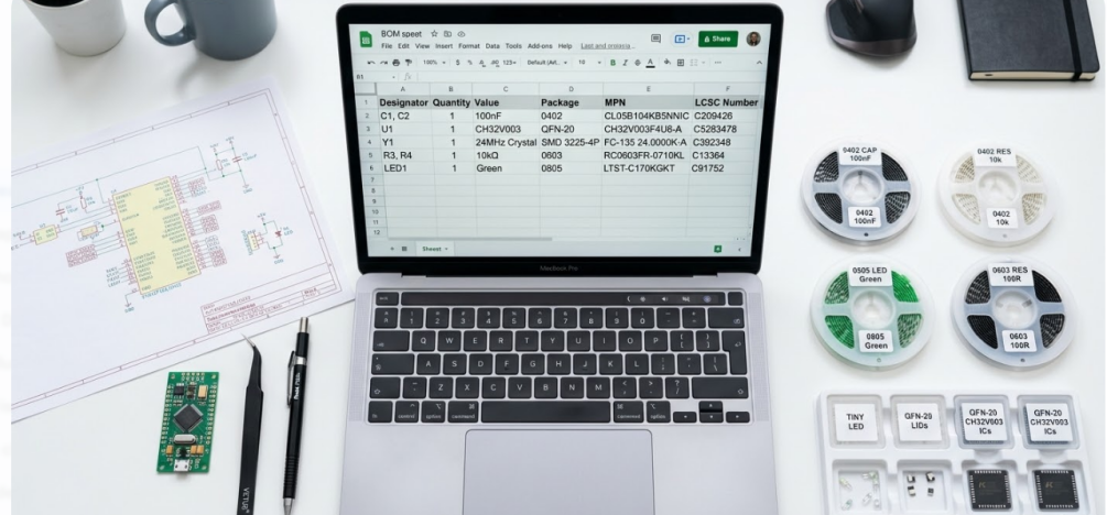
Have you ever sent a PCB design to be assembled only to receive an email requesting why you have not provided a part number or the package has not been matched? In that case, you are already aware that a single slip in your bill of materials will bring a flawless board down. Take a small CH32V003-based dev board consisting of 29 components distributed on 11 different footprints on a 2-layer copper PCB. It has an MCU, USB-C input, 24MHz crystal, USB-to-TTL bridge, indicator LEDs, and programming/GPIO header. The functional diversity that fits into such a small design. The assembler cannot be confident that the correct 5.1 k oh CC resistors will be connected to the USB -C lines, the correct 100 nF decoupling caps will be selected, or that the LEDs will be the correct package and color without a clean BOM.
Today we are going to take the tour of what precisely makes a BOM bulletproof. We will discuss the required columns of any BOM, the best practices in version control and cost optimization, most frequent traps that lead to delays in production and how the JLCPCB assembly process can assist you to identify issues early before they prove to be costly. These principles apply whether you are developing your first prototype or are getting ready to produce in large quantities.
Why a Strong Bill of Materials Is the Foundation of Successful PCB Projects
What Is a Bill of Materials and Its Role in PCB Manufacturing
A bill of materials (BOM) is, in effect, the single document that informs all the components on your PCB. It contains part IDs, the quantity of parts, the package, and the location. Imagine it is a recipe card on the board. Missing it, the assembler is merely shooting in the dark, and the shooting in the dark in electronics assembly can be very expensive.

It is literally dependent on close correspondence between the manufacturer part number (MPN) and the footprint on the board and the reference designator in the schematic that makes or breaks the quality of PCB assembly. The pick-and-place tool will either drop the incorrect part or tantrum in case one of those is not on. In a board such as our CH32V003, where we are combining blocks such as USB power, voltage regulation, an MCU core, and serial comms, the BOM must be extremely detailed to ensure that no one down the line can guess what we are doing. An MCU decoupling 100nF in a 0402 is not on the same procurement line as 1mF in a 0805 beside the LDO. The BOM should spell that out.
Real-World Consequences of Poor BOM Management
In such a case as when an MPN is not in place, or the package code does not match the footprint, an assembly line simply stops. The manufacturer creates a support ticket, awaits your response, and the timeline of your build shifts even further. And possibly a defective component could be soldered, which increases the costs and the reliability risk due to additional thermal cycles. Another hiccup is the lack of lifecycle or supply-chain information. You screw down a particular USB-to-TTL converter, place the BOM, and three weeks later, you realize that the part will have a 16-week lead time.
You find yourself at the last minute making a last-minute alternative that is not pin compatible or may not be electrically the same. This can be completely prevented through preliminary supply-chain checks. Irregular designators in your BOM and schematic are another pain in the neck. When your schema identifies the crystal as Y1 but the BOM identifies it as X1, then the BOM and the placement file are not in agreement. Automated assembly will alert to the discrepancy and discard the file, and you will have to go back and forth before you finally see your boards shipped.
Essential Elements Every Effective BOM Must Include
Component Details, Quantities, and Alternative Parts
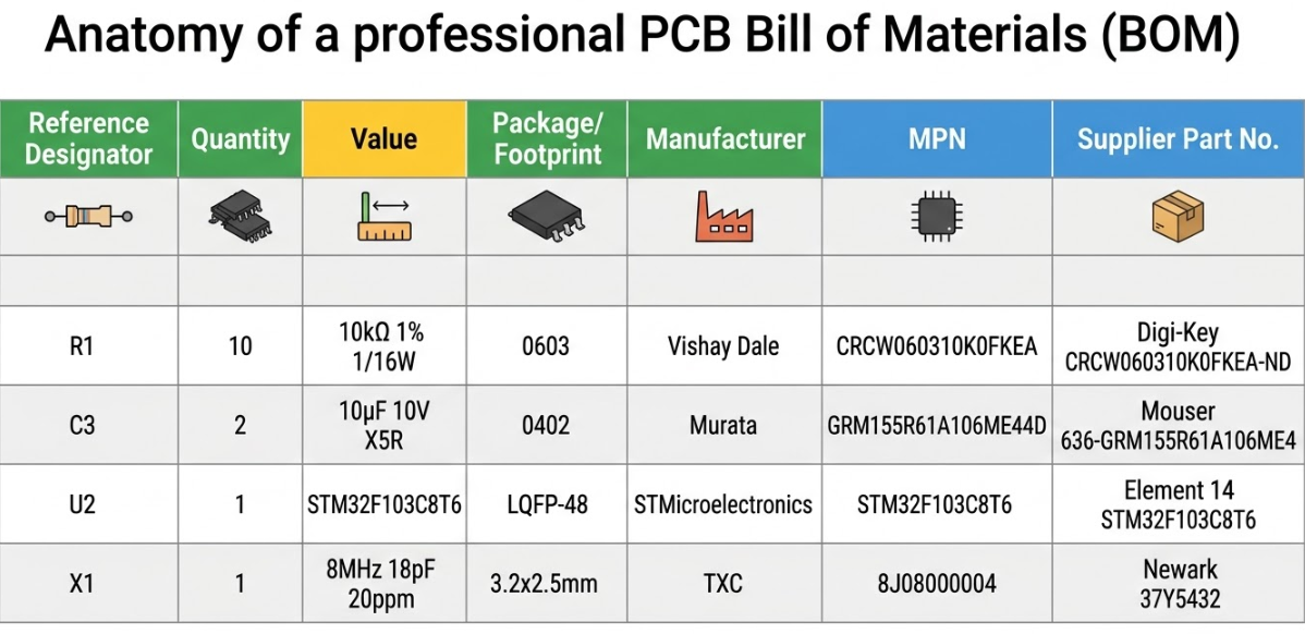
Every professional BOM needs a set of mandatory columns that leave no room for ambiguity. At minimum, you need the following for each line item:
1. Reference designators: the specific callouts from the schematic (R1, R2, R5)
2. Quantity: how many of that component are placed per board
3. Value: the electrical value with units (5.1k ohm, 100nF, 24MHz)
4. Package/Footprint: the physical size code (0402, 0805, SOT-23)
5. Manufacturer: the component maker (WCH, Murata, Yageo)
6. MPN: the exact manufacturer part number, no shorthand
For your CH32V003 board, this means the two 5.1k USB-C CC resistors share a BOM line with a quantity of 2 and both designators listed. The 24MHz crystal gets its own line with the exact MPN that matches the load capacitance you designed for.
Manufacturer Part Numbers and Supply Chain Information
The MPN is the single most important field in your BOM. Use the full, exact part number as it appears in the manufacturer datasheet. Never abbreviate. A shortened or modified MPN forces the assembler to guess, and guesses lead to wrong parts on your board.
When using JLCPCB's assembly service, adding the LCSC part number alongside the MPN streamlines the sourcing process significantly. JLCPCB's parts library is indexed by LCSC numbers, so including them eliminates a manual lookup step and reduces quoting time.
For critical components like the CH32V003 MCU, the USB-to-TTL bridge IC, and connectors, you should also track lifecycle status and typical lead times. A part marked "Not Recommended for New Designs" in a distributor database is a ticking time bomb in your BOM. Catch it early, find an alternate, and document both options.
| BOM Column | Example (CH32V003 Board) | Required? |
| Reference Designator | R3, R4 | Yes |
| Quantity | 2 | Yes |
| Value | 5.1k ohm | Yes |
| Package | 0402 | Yes |
| Manufacturer | Yageo | Yes |
| MPN | RC0402FR-075K1L | Yes |
| LCSC Number | C25905 | Recommended |
| Alternate MPN | CRCW04025K10FKED | Optional |
| Lifecycle Status | Active | Recommended |
Best Practices for Creating a Professional-Grade Bill of Materials
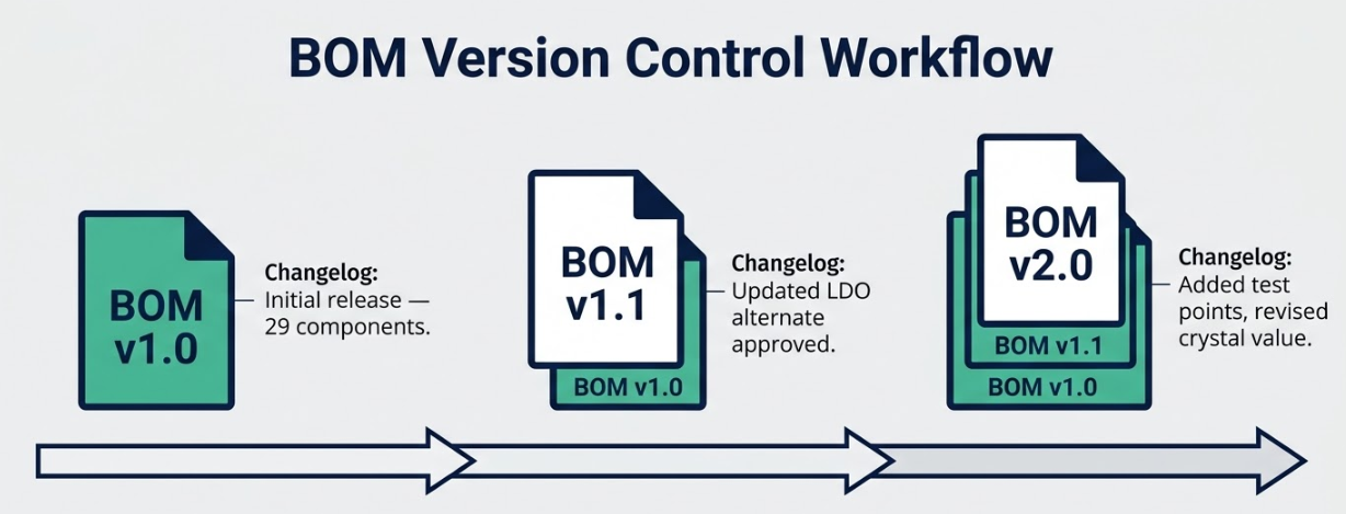
Organizing Structure and Version Control
Make your BOM your class notes. Whenever your PCB design has a new version, lock the BOM to the same version. Label it, such as CH32V003_DevBoard_v1.2 BOM, and maintain a changelog, with a statement about the nature and reason of changes. It is a lifesaver where you have to re-arrange the boards six months later or debug a field problem in an older version.
Lock your reference designators before releasing the BOM. If designators shift between schematic revisions, previously validated placement files become invalid. This is especially important when your BOM and CPL (Component Placement List) are generated from the same design snapshot, which they always should be. A BOM from Tuesday and a CPL from Thursday is a recipe for misalignment.
Integrating DFM Feedback and Cost Optimization
In a DFM review, look out how to reduce pretty unique passive values, in a collapsed manner. When your design has both 47 nf and 56 nf caps and your circuit is capable of absorbing the difference, the standardization to a single value reduces the number of unique parts and makes procurement much easier. On a 29 component board, removing a single unique passive saves a line on the BOM, a feeder slot and possibly a sourcing delay.
Pre-approve alternates for commodity values like decoupling capacitors and pull-up resistors. These are the parts most likely to experience stock fluctuations, and having a second approved option lets the assembler keep moving without waiting for your approval. Always validate part availability before submitting your final BOM to assembly. A five-minute check on JLCPCB's parts library can save you days of delay.
Using BOM Software Tools Efficiently
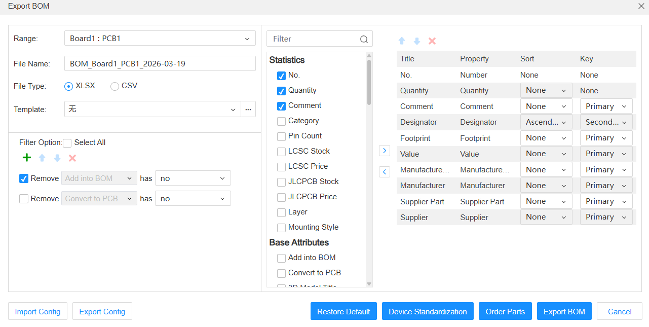
Whenever possible, simply export the BOM out of your EDA software. The omission of the hand-typing process between the schematic and a spreadsheet eliminates a host of copy-pasting errors. Each of the KiCad, EasyEDA and Altium Designer vendors are shipping a BOM generator that will retrieve data directly out of the schematic, so just use those instead of typing all that by hand.
After export, run a set of sanity checks before submission:
1. Scan for duplicated reference designators that would indicate a schematic error
2. Flag any rows with missing MPNs or blank package fields
3. Verify that every value and package combination matches a real, orderable component
4. Cross-check BOM designators against the CPL file to confirm one-to-one mapping
5. Confirm total component count matches your design (29 components for the CH32V003 board)
Keep a release checklist specifically for BOM and CPL consistency. This is a two-minute investment that prevents hours of back-and-forth with the assembler.
Common BOM Pitfalls and How Professional Manufacturing Avoids Them
Missing or Incorrect Component Data
The number one cause of assembly questions from the manufacturer is a missing package field or unclear value formatting. Writing "100n" instead of "100nF" or leaving the package column blank for a resistor forces someone to stop and ask. That question-and-answer cycle adds a day or more to your build timeline.
The polarity or orientation data of LEDs and connectors are sometimes scattered everywhere and to be quite honest, this can be a pain. You have to use the exact name of the part of the LED that you are using in your BOM, as that is what the pick-and-place robot uses to determine the anode and cathode orientation. The indicator LEDs on the CH32V003 board require you to enter the entire MPN in the BOM to allow the assembler to open the entire datasheet and automatically verify the orientation. The solution is incredibly simple. Simply just lock in a BOM template with all the columns needed. In case of a blank spot, either run your export script or use a checklist to indicate the blank spot before the file is even delivered to the manufacturer.
Supply Chain Risks and Obsolescence Issues
Single-source components are the biggest schedule risk in any BOM. If only one manufacturer makes the part and they experience a shortage, your project stops. This is particularly relevant for specialized ICs like the CH32V003 MCU, where cross-manufacturer alternates may not exist. For parts without alternates, maintain buffer stock or plan your ordering around known lead times.
For commodity parts like resistors, capacitors, and standard LEDs, always add at least one alternate source. Include preferred distributor links so the purchasing team does not have to research options under time pressure. Recheck availability right before placing your order. Stock levels change daily, and a BOM validated two weeks ago may have stale assumptions about a key component.
How Early BOM Review Prevents Production Delays
A pre-submission BOM review is the single most effective way to prevent production delays. Spending 30 minutes reviewing your BOM against the schematic, the CPL, and the parts library catches non-orderable or mismatched items before they become blocking issues on the factory floor.
Fabricator feedback is another powerful tool. When you upload your BOM to JLCPCB's order system, their review process checks for common formatting issues and part availability. This feedback loop closes gaps before parts are purchased and assembly begins. Aligning your BOM, CPL, and PCB revision into a single validated package prevents the new product introduction churn that plagues disorganized projects.
JLCPCB's Expertise in Turning BOMs into High-Quality Production
Advanced BOM Validation and Sourcing Support
JLCPCB provides specific guidance around BOM and CPL formatting requirements, helping you get the file structure right the first time. Their system checks for common issues like missing part numbers, unrecognized packages, and designator mismatches during the upload process. This automated validation, combined with engineering review, catches problems that manual checks often miss.
Early BOM cleanup reduces both quoting time and assembly iteration cycles. When your BOM arrives clean and complete, the quote comes back faster and the assembly process starts without delays. For a board like the CH32V003 design, a well-structured BOM with LCSC part numbers already mapped means the order can move from quote to production with minimal friction.
Seamless Integration from Design to Full-Scale Assembly
A clean BOM is the bridge between your design files and the SMT pick-and-place programming. Every feeder on the assembly line is loaded based on your BOM data. Every component placement is verified against your CPL data. When these files are consistent and accurate, first-pass assembly success rates are dramatically higher.
JLCPCB's assembly workflow, with PCB fabrication starting from $2 and SMT assembly services integrated into the same order flow, is designed around this principle. Consistent reference designators, verified package definitions, and validated MPNs feed directly into their production system. The result is predictable builds with fewer engineering queries and faster turnaround, often within days for prototype quantities.
Proven Track Record Delivering Reliable PCB Boards on Time
When BOM discipline is maintained across a project, build outcomes become predictable. You submit files, receive boards, and they work. That sounds simple, but it is the result of systematic attention to every column in your BOM from the very first schematic capture.
Your CH32V003 development board, once validated with a clean BOM, becomes a reusable template for future variants. Need to swap the MCU for a CH32V003D? Update the MPN, verify the footprint compatibility, increment the revision, and resubmit. The BOM structure carries forward, and the assembly process stays smooth.
Frequently Asked Questions (FAQ)
Q1: What minimum columns should never be missing in a PCB BOM?
At minimum, every BOM row must include reference designator(s), quantity, value with units, package or footprint code, manufacturer name, and the full manufacturer part number (MPN). Omitting any of these forces the assembler to make assumptions, which increases the risk of wrong parts being placed.
Q2: How should alternate parts be documented to avoid assembly confusion?
List alternates in a dedicated column labeled "Alternate MPN" or "Approved Substitute." Include the full MPN and manufacturer for each alternate. Add a note specifying whether the alternate is a direct drop-in replacement or requires any design consideration. Never mix primary and alternate parts in the same MPN field, as this creates ambiguity about which part the assembler should source first.
Q3: Should I group all identical resistors/capacitors or list each designator row?
Group identical components onto a single BOM row with all designators listed in the designator field (e.g., "R1, R2, R5") and the correct total quantity. This keeps the BOM concise and reduces the number of unique line items the assembler needs to process. However, always list every individual designator so that the BOM-to-CPL mapping remains traceable.
Q4: How do I keep BOM and CPL synchronized across revisions?
Always generate both files from the same design snapshot at the same time. If you update the schematic or layout, regenerate both files together. Include the PCB revision number in the filename of both documents. Before submission, cross-check that every designator in the BOM appears exactly once in the CPL, and that the total component count matches.
Keep Learning
Why Specific File Formats Are Essential for Ordering PCBs
Ordering printed circuit boards (PCBs) involves providing precise and detailed information about the design and specifications. Without the right file formats, even the most brilliant PCB design can lead to manufacturing delays, costly errors, or complete production failure. This is why specific PCB file formats are necessary. Manufacturing can only proceed successfully with a complete set of production files, including schematic designs, Bill of Materials (BOM), PCB layouts, and stack-up information.......
DFM's Key Role in PCB Manufacturing
DFM in PCB design stands for Design for Manufacturability. In today’s highly digitized electronic era, printed circuit boards (PCBs) serve as the backbone for connecting and supporting electronic components. The quality and efficiency of PCB manufacturing are largely determined by Design for Manufacturability (DFM)—the practice of designing with manufacturing requirements in mind from the very beginning. DFM plays a crucial role in enhancing manufacturing efficiency, reducing costs, and ensuring the q......
Breaking Down PCB Pricing: How is the Cost Determined
PCB quote packaging involves gathering and organizing all the necessary details to estimate the cost of manufacturing a PCB. This process includes not only design specifications but also material selection, manufacturing methods, and engineering considerations. It goes beyond a simple financial estimate and provides a thorough engineering analysis to ensure the quote is accurate, feasible, and optimized for production. Every aspect affecting production such as material type, size, complexity, and prod......
How to Choose the Right Solder Wire for Your Projects
Solder hails from the middle english word soudur, which derives from the latin word solidare, meaning "to make solid." It's a fusible alloy (i.e. low melting point) used to bond metal workpieces together. Solder is a material that is used to bond objects, such as pipes or wires, together permanently. The primary application for soldering in the plumbing industry is leak-free connections. In the electronics industry, soldering is used to fuse wires for circuit components. Soldering is an essential skil......
Lead-Free vs Lead Solder: What’s the Real Difference?
Solder is used by the majority of electrical devices to connect components to PCBs. The procedure of soldering is, when a solder melts down it will make a connection. This connection can be between pads or wires. Soldering is not like welding, we can attach the two joints by heating them again a lil bit. Although after performing the soldering step the curing and cooling is required. If during the cooling step there is any disturbance occur in the system it will lead to dry joints. Two main varieties ......
How to Build a Bulletproof Bill of Materials for Flawless PCB Production
Have you ever sent a PCB design to be assembled only to receive an email requesting why you have not provided a part number or the package has not been matched? In that case, you are already aware that a single slip in your bill of materials will bring a flawless board down. Take a small CH32V003-based dev board consisting of 29 components distributed on 11 different footprints on a 2-layer copper PCB. It has an MCU, USB-C input, 24MHz crystal, USB-to-TTL bridge, indicator LEDs, and programming/GPIO h......