
Integrating Standoff Spacers in PCB: Key Considerations for Mechanical Reliability and Performance
11 min
- Material Selection for Optimal PCB Compatibility
- Understanding Standoff Types in the Context of PCB Layout
- Design Integration Best Practices for Standoff Spacers
- Real-World PCB and PCBA Applications and Optimization Strategies
- Frequently Asked Questions (FAQ)
Standoff spacers are essentially small posts that serve as supports for circuit boards. They are much more than just small parts in a PCB assembly. These components work by lifting the PCB a bit, which then allows for proper airflow. So there will be better insulation and mechanical support. Standoffs keep a board steady and prevent it from touching other pieces. Choosing a good standoff can really change things; it ensures your device works right instead of failing or coming apart. With this, they are able to create a space for air to circulate under the parts, which is a sensible design choice. Maintaining proper spacing in tight groups is really important for both cooling and safety.
Ensuring Secure Mounting and Vibration Resistance
Metal standoffs stabilize and support circuit boards against bending or breaking from movement between industrial controllers and server housings. Metal standoffs provide stability for oversized circuit boards against being bent from excessive movement by providing metal supports for the circuit board. Fasteners (primarily screws) often incorporate washers which provide additional protection against over-tightening of fastener joints. To properly secure circuit boards, fasteners and standoffs must be placed in a manner that allows the circuit board to sustain multiple loads and shocks from drops and other impacts without incurring damage. Standoffs may be thought of as shock absorbers by providing a secure anchor point to the circuit board. If Standoffs Are Not Used With A Circuit Board, The PCB Will Be Subjected To Damage Due To Cracks And Short-Circuits
Supporting Heat Dissipation and EMI Shielding in Dense Layouts
By raising a PCB off its mounting surface, standoffs provide the board with breathing room. This feature really helps in dense boards, and it translates directly into better cooling. Air can flow around and under components, carrying heat away from hotspots. Designers often intentionally leave gaps and even add small fans beneath crowded PCBs to enhance convection. In multi-board assemblies, such as stacked RF modules, standoffs are essential components to add.
Metal standoffs offer a practical benefit as they can be used as grounding posts. It helps in connecting the board's ground to the chassis itself. Always keep in mind that the shielding is completed as a 360-degree connection from the cable to the main connector. This connection allows the metal enclosure to act as an EMI shield. It is essentially giving the circuit board an ideal foundation for operation. Standoffs do more than just keep parts from touching, which stops shorts. They also create paths that conduct heat away and form small spaces that help control EMI.
Material Selection for Optimal PCB Compatibility
Conductive Metals for Grounding and Thermal Pathways
Typically, brass, aluminium and stainless steel are the main materials to be used as standoff spacers.
- Brass is commonly used due to its high resistance to corrosive attack. It has exceptional electrical conductivity and ease of machining. It can be soldered directly to a circuit board's ground plane if necessary.
- Aluminum is lighter than brass but has comparable strength. Engineers frequently choose aluminum as a standoff material for any application where good thermal conductivity is required.
- Stainless steel is the strongest and toughest material out of the three options above. Stainless steel standoffs are heavier compared to brass, and have slightly provide less capacitance.
However, they add weight and must be kept from causing shorts. As one design guide notes, use a metal standoff spacer if your goal is to maintain electrical conductivity. Aluminum is fine as long as it’s not anodized.
Insulating Plastics for Electrical Isolation and Weight Reduction
Insulator materials like plastic and nylon are cost-effective as standoffs. As insulators help prevent unwanted electrical currents or short circuits. They are also lighter than metal and often cheaper in bulk. Common types of plastics include nylon, acetal and polystyrene. Nylon is flexible but does take in water eventually, which can lead to changes in its size and shape over time.
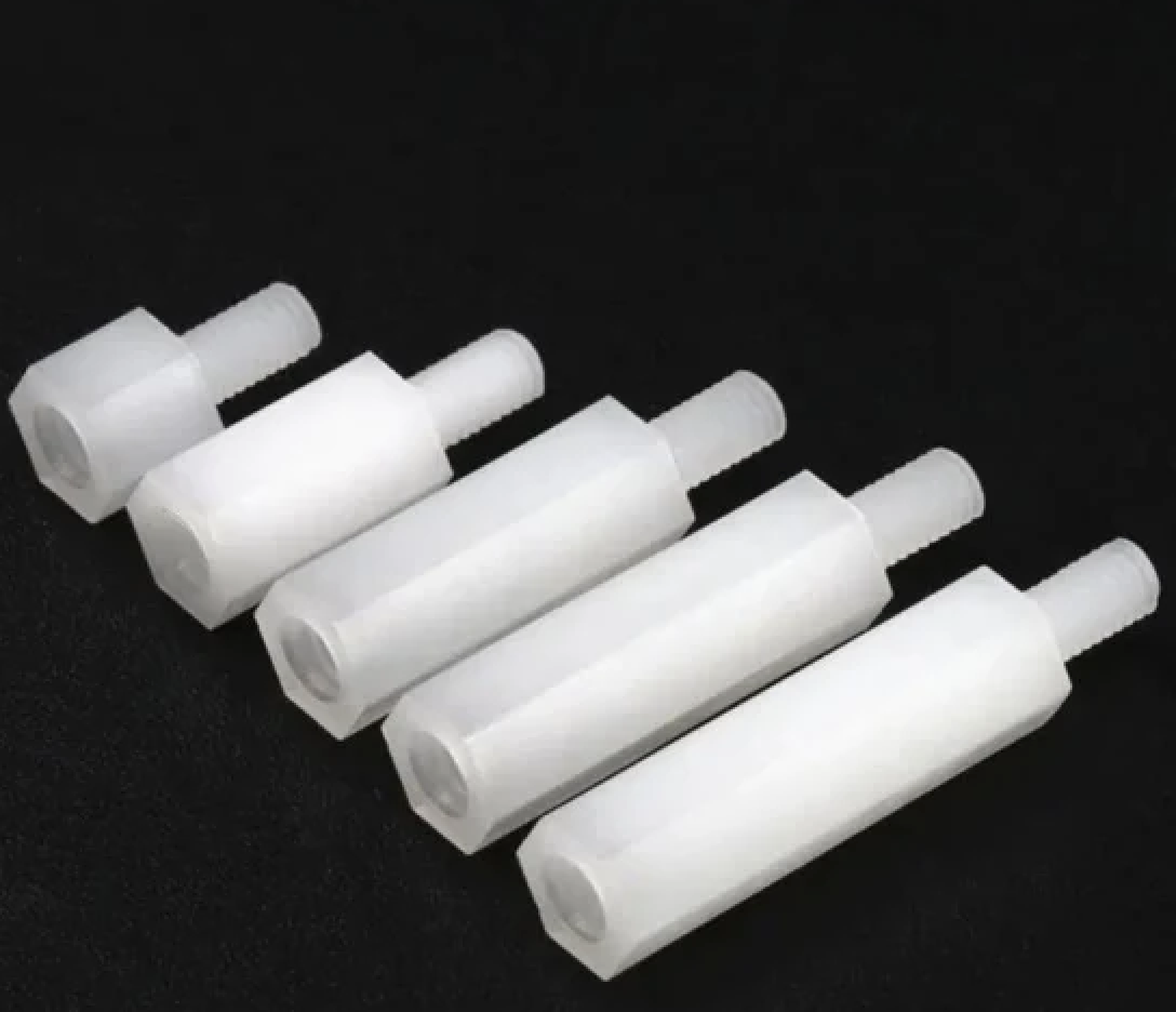
So, designers are careful about using nylon in very humid or hot places. Plastic offers good chemical resistance and is quite light. These work well when you just need to raise a board and wish to keep the expenses and mass low. They come in self-locking or snap-fit designs, providing convenience for various applications. But plastics can change shape if they are under a lot of weight or in very warm conditions. For this reason, they are not usually chosen for these situations.
High-Performance Materials for Harsh Environment Applications
For very high temperatures or chemically aggressive conditions, ceramics and high-performance polymers come into play. Ceramic spacers are essentially tiny ceramic tubes. That can handle heat that would melt most plastics, some ceramic beads won’t softeneven above 1000 °C. They provide excellent insulation under extreme temperature loads and won’t burn. Thus, ceramic standoffs are used to space off hot components or in military avionics. In summary, if a PCB will see extreme temperatures or stress, designers will reach for these high-end spacer materials to ensure the standoff does not become a weak link.
Understanding Standoff Types in the Context of PCB Layout
Threaded Designs for Precise and Adjustable Mounting
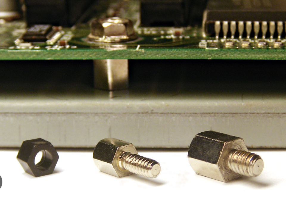
Most standoffs you have seen in pictures are threaded. These have either internal or external threads. A male-female standoff has an external thread at one end and an internal thread at the other. They are extremely handy for stacking boards or mounting the PCB to a panel. You simply thread the male end into one board or chassis hole, then screw another board onto the female end. Female-female standoffs are threaded on both sides and act like a fixed spacer into which male screws attach.
There are also male-male standoffs that serve as adapters. These threaded posts allow for precise control of spacing by using different lengths. Many threaded standoffs have hexagonal bodies, so you can tighten them with a wrench. As they may provide more torque and make assembly easier. Round standoffs save space but can be harder to screw in by hand.
Snap-Fit and Unthreaded Options for Streamlined Assembly
Not all fixtures need screws; there are also Snap-fit or press-fit spacers. These are molded plastic posts that “pop” into the PCB hole or mounting panel without threads. These can greatly speed up assembly because no tool is needed. In many consumer products, boards clip into a plastic enclosure via built-in standoffs or slots.
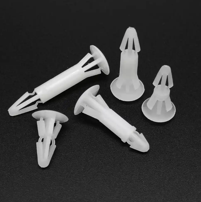
While snap-in standoffs are very convenient, they trade off some strength. The quick-mount clips are ideal for high-volume, low-cost electronics. But they are generally not recommended for environments with heavy vibration or heat. If you need a permanent mount but still want tool-less assembly, there are also push-on nut-like standoffs. In general, any time you see a board click into place by hand, you’re likely looking at a snap-fit support or standoff.
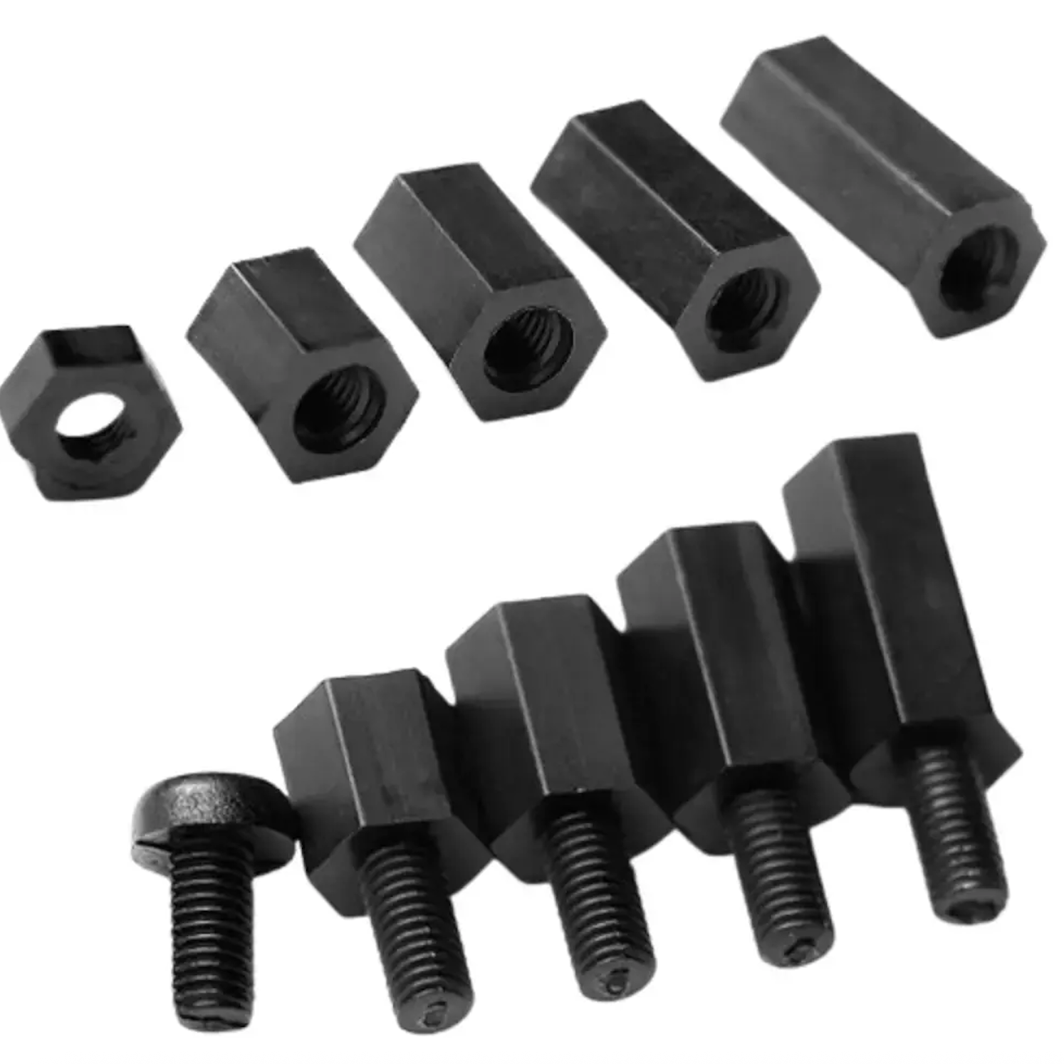
Male-Female and Hex Variants for Multi-Board Configurations
Certain standoff variants are designed specifically for complex builds. For instance, male-female hex standoffs combine the stackability of threaded posts. These let you assemble multiple boards in a tower. The male end screws into the bottom board and the upper board screws onto the female top. This reduces the number of screws needed and keeps everything aligned. Because they are hex-shaped, you can tighten both ends easily and adjust height by choosing longer or shorter versions.
There are also stacking standoffs which snap together. These consist of two interlocking plastic pieces. One fixed to the bottom board and one to the top board, which then mate. They lock into a fixed distance, creating a secure multi-board assembly without extra screws. By mixing and matching these components, you can stack and arrange PCBs almost like building blocks, ensuring both stability and ease of assembly.
Design Integration Best Practices for Standoff Spacers
Coordinating Hole Placement and Tolerance with PCB Footprints
Before adding standoffs we have tp decide where the mounting holes will go. Mounting holes should be aligned symmetrically to balance support. According to manufacturing best practices, these holes must be sized and spaced to match your chosen hardware. For example, if you use M4 screws, make sure the PCB has clearance holes that that screw can pass through without scraping. The holes in the board should usually be slightly larger than the screw (0.2–0.3 mm clearance) to accommodate drilling tolerance. It’s also wise to keep copper at least 0.5 mm away from the hole edges.
Balancing Load Distribution and Clearance in Enclosure Designs
The placement and position of holes is determined by the load distribution on the PCB. We want to make sure that we don't put excess stress on any one area of the board. For larger PCBs or those with heavier parts, use multiple standoffs. Evenly spreading support points helps distribute the stress if the device is hit or shaken, We could also consider the force of the standoffs. It’s also important to not overtighten screws, as they may cause warping in the board. Each standoff and spacer occupies space in the enclosure. Check that the standoffs, once mounted, don’t obstruct any other parts or wires. In compact layers, use the shortest standoff that still gives clearance to the tallest component below.
Impact on Signal Integrity and Thermal Management in PCBA
Although standoffs are mechanical hardware, they can subtly affect electrical performance. For signal integrity, the primary concerns are grounding and noise. A metal standoff connecting to ground can actually improve shielding. But a poorly placed metal posts can also create tiny ground loops if the chassis and board ground aren’t planned properly. To minimize any negative effects, keep high-speed signals away from mounting holes. Use ground vias or planes to ensure continuous return paths.
On the thermal side, standoffs usually help rather than hurt. By lifting the board, they promote airflow. In hot designs, you might actually use thermal standoffs. Metal spacers that contact a heatsink or metal backplate to bleed heat away from the PCB. Conversely, if a board has components on both sides, consider stacked standoffs with ventilation. In any case, always review the thermal path in the final design. Check that standoffs do not block vents or trap heat pockets.
Real-World PCB and PCBA Applications and Optimization Strategies
Industrial and Automotive Systems Requiring Robust Fixing
In industrial and automotive electronics, the boards are more prone to vibrations and temperature swings. For example, in power electronics design, you’ll often see thick metal standoffs and screws holding thick PCBs. These systems use steel or stainless steel standoffs to resist mechanical fatigue. Automotive modules use zinc-plated or stainless steel to resist road salt and shock. In such cases, designers follow strict mechanical standards. Manufacturers like JLCPCB offer assembly standoff services for these scenarios. For instance, JLCPCB allows customers to order PCBA with pre-installed standoffs. The guidelines emphasise on choosing the right height to avoid bending of pins.
High-Density Consumer Electronics and Multi-Layer Stacking
Consumer electronics, where the demand is for miniaturisation and multiple boards are packed into a tiny space. Standoffs in these designs are usually shorter and lighter. Engineers frequently use stackable spacers or moulded clip mounts. For example, a camera module in a smartphone might be mounted on a small PCB that snaps onto the main board. Thermal considerations are still important. In some laptops, the aluminum chassis itself is anchored to the board with conductive standoffs. Which help to channel heat and stabilize the board.
How Professional Manufacturing Ensures Seamless Spacer Integration

Modern PCB fabrication and assembly houses recognize standoffs as integral parts of the design. They provide guidelines and services to integrate spacers seamlessly. For example, Proper hole sizing and spacing are important for maintaining mechanical stability of the PCB. Fabrication tolerances on drill size and hole position mean designers often specify slightly oversized holes or build in copper keepout areas. During assembly, machines and operators follow design notes: if a standoff is specified, the BOM and assembly drawings will call it out.
Quality is also enforced through testing, a high-quality assemblies use durable standoffs. All to prevent loosening and mechanical failure over time. Some manufacturers reinforce the PCB around mounting holes to prevent pull-through. In summary, professional manufacturing treats standoff integration not as an afterthought but as a critical step.

Frequently Asked Questions (FAQ)
Q: What is the difference between a standoff and a spacer?
A: A spacer is a plain tube and needs nuts on both sides. A standoff has threads, so screws go directly into it.
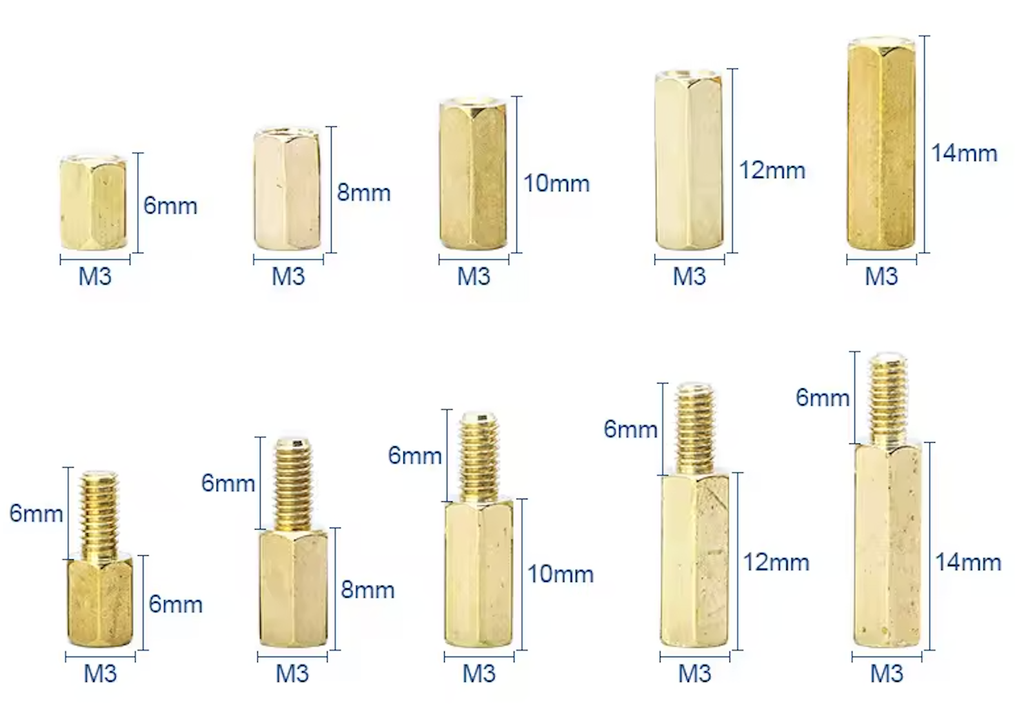
Q: How do I choose the correct standoff height?
A: Pick a height taller than the tallest component, with extra clearance. Common sizes are 5–25 mm.
Q: Should I use metal or plastic standoffs?
A: Use metal for strength or grounding. Use plastic/nylon for insulation, low cost, and lightweight.
Q: Can snap-fit standoffs replace screws?
A: Yes for quick, low-stress assemblies. No for vibration, heavy loads, or critical hardware.
Popular Articles
• Understanding the Basics of Electronic Devices and Circuits
• Choosing the Right Electronic Components for Your Electronic Design: Tips and Best Practices
• PCBs Explained: A Simple Guide to Printed Circuit Boards
• Guide to the Top 10 Commonly Used Electronic Components
• Digital 101: Fundamental Building Blocks of Digital Logic Design
Keep Learning
Understanding the Basics of Electronic Devices and Circuits
In the realm of modern technology, electronic devices and circuits play a crucial role in powering everything from everyday gadgets to complex machinery. Understanding the fundamentals of these components can provide valuable insights into how various electronic systems operate and interact. This blog explores the basics of electronic devices and circuits, their types, functions, and the significance of their design in today's technological landscape. Electronics means the study of the flow of electro......
Optimize PCB Trace Spacing for High-Performance PCBs
Key Takeaways Trace Spacing vs. Clearance: Trace spacing is the edge-to-edge distance between copper conductors on the same layer, while clearance encompasses the broader safety envelope between traces and non-trace features like board edges and mounting holes. The 3W Rule: For high-speed signals, maintain at least 3x the trace width between centerlines (2W edge-to-edge spacing) to reduce crosstalk by up to 70%. IPC-2221 Standards: Industry-standard clearance values depend on voltage levels, altitude,......
PCB Board Outline: Smart Design Tips for Seamless Manufacturing
Key Takeaways Board Outline Defined: The closed polygonal contour on Mechanical Layer 1 that defines your PCB's final physical boundary, including cutouts, slots, and mounting holes. Why It Matters: Directly impacts enclosure fit, mechanical stability, assembly efficiency, and production yield — a well-designed outline reduces costs and lead times. Critical Parameters: Maintain ≥0.2 mm edge clearance, use ≥0.5–1.0 mm corner radii, and specify tolerances appropriate to your routing method (±0.1 mm prec......
Dimensional Stability in PCB Manufacturing: Precision Solutions for Reliable PCBs
Key Takeaways Dimensional stability is a PCB’s ability to maintain precise dimensions and flatness under thermal, humidity, and mechanical stresses. It is essential for accurate layer registration, preventing warpage, via cracks, and assembly failures in multilayer boards. Achieving this requires high-Tg FR-4 materials with low CTE, symmetric stack-ups, balanced copper, and tightly controlled lamination. Professional manufacturing delivers <0.75% bow/twist and ±0.1 mm tolerances, ensuring higher yield......
Types of PCB Boards: Ultimate Reference with Specs & Use Cases
A printed circuit board (PCB) consists of laminated insulating and conductive materials that connect multiple electrical devices. A PCB can be thought of as a layered composite of fibreglass and epoxy with copper patterns etched onto it. These serve as electrical conductors and pathways for signals and power. A PCB can be Simple (one layer of conductive material), Double-Sided (two conductive layers), or Complex (three or more conductive layers) to allow numerous circuit paths on a small piece of hard......
PCB Layers Explained : Building Better Boards Through Smart Stackup, Standards, and Design Practices
A PCB is a sandwich of copper and insulating sheets that are stacked together to form a circuit board. Each PCB layer has a specific purpose; for example, some carry signals (traces connecting components), while others serve as solid planes for power or ground. Think of PCB layers like the floors in a building, where each floor can have a different role. We can think of it as offices (signals) on one floor and storage (ground/power) on another. The number of layers varies by design complexity, from ju......