
Choosing the PCB Laminate for Reliable High-Performance Boards
12 min
- The Foundation of Every PCB – Understanding Laminate Materials
- Common Types of PCB Laminates and Their Characteristics
- Key Factors to Consider When Selecting PCB Laminates
- Design and Manufacturing Implications of Laminate Choice
- JLCPCB's Expertise in PCB Laminate Selection and Fabrication
- FAQ about PCB Laminate
- Conclusion
Key Takeaways
Choosing the right PCB laminate is the foundation of a reliable high-performance board. Match your material to the application — standard FR4 for basic designs under 5 GHz, high-Tg FR4 for lead-free assembly, low-loss materials for high-speed digital, and Rogers/PTFE for RF and mmWave applications. Always prioritize stable Dk, low Df, high Tg, and low Z-axis CTE while recalculating your stackup for accurate impedance control. Partnering with an experienced manufacturer ensures optimal processing and consistent results from prototype to production.
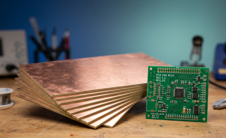
Ever wonder what is on your circuit board before any copper trace is routed or any component is placed? Below each footprint and through each via is the PCB laminate, the engineered material that holds your entire design together. Easy to overlook, it quietly determines whether or not your board lives through reflow, maintains its impedance, and outlasts you in the field for years. Most engineers spend their time thinking about part selection and routing, but it all starts with the laminate. Even a perfect schematic can be ruined by a poor choice, resulting in a lost signal at high frequencies, delamination under thermal stress, or an out-of-tolerance impedance.
The right laminate, on the other hand, provides your design with a stable and predictable base. This guide will dissect what PCB laminate is, the various types from common FR4 to exotic high-frequency materials, and a step-by-step walk-through of various electrical and thermal factors involved in selecting the correct laminate material. We will also examine the impact of your laminate selection on stackup planning, impedance control, and within the actual fabrication process.
The Foundation of Every PCB – Understanding Laminate Materials
What PCB Laminate Is and Its Critical Role in Board Construction
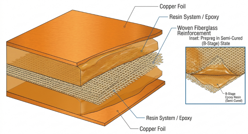
A PCB laminate is a material that is composed of a reinforcement, which is typically woven fiberglass cloth, and impregnated with a resin system, usually epoxy, and cured and clad with copper foil. Copper-clad laminate (CCL.) is a laminate of copper foil on one side or both sides. The fiberglass weave usually accounts for 30% to 50% of the laminate's weight and imparts mechanical strength and toughness to the laminate, and helps to stabilize the dimensional characteristics. The resin will hold everything together and serve as the insulating material between copper layers. In multilayer construction, partially cured sheets, called prepreg, are used to laminate the cured cores.
How Laminate Properties Influence Overall PCB Performance
The attributes of the laminate influence the actions of your board. The following are the most important attributes:
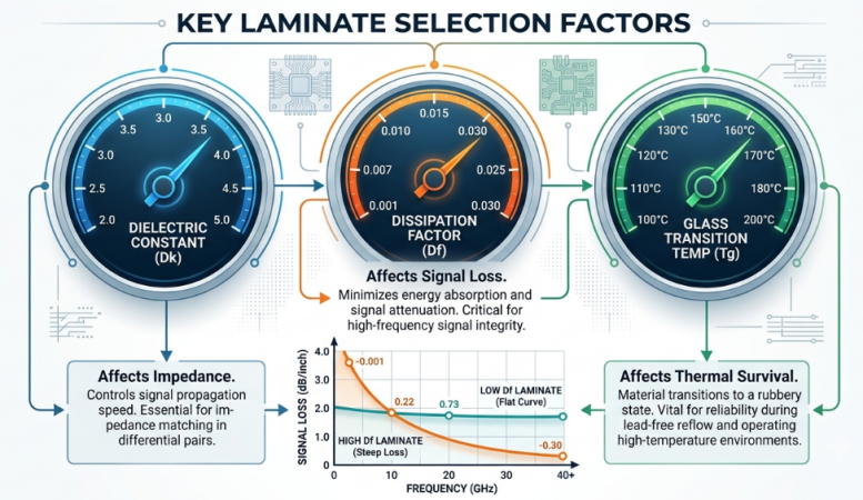
- Dielectric constant (Dk): the influence on the propagation speed of the signal and impedance. Trace impedance is predictable with a stable Dk.
- Dissipation factor (Df): Governs dielectric loss. The lower the Df, the better the signals at high frequencies will be.
- Glass transition temperature (Tg): The temperature at which the resin becomes soft. The greater the value of Tg, the greater the number of thermal cycles to which it will survive.
- Coefficient of thermal expansion (CTE): regulates the amount of expansion of the board when heated, particularly in the Z axis, where via reliability is critical.
- Thermal conductivity: influences the dispersion of heat from the hot elements.
Common Types of PCB Laminates and Their Characteristics
Standard FR4 and Its Limitations
For most boards, the laminate material used is FR4, and for a good reason – it's the default choice for laminate material. The "FR" in the name does not indicate that it is flame-proof in itself, but that it is a woven glass and epoxy composite that is inexpensive, mechanically robust, and easy to fabricate, and is flame-retardant. Standard FR4 offers a Dk around 4.2 to 4.7 and a Df of roughly 0.017 to 0.025, with a typical Tg between 130 and 180 °C. But there are some limits with FR4. The dielectric loss rises sharply with frequency, and Dk has a significant variation over the frequency band, making the impedance control difficult at high speeds. There is also fiberglass weave, which causes local Dk variation, and this is a problem for tightly matched differential pairs over 5 GHz. With RF, microwave, and very high data-rate links, FR4 is just too low.
High-Tg, Low-Loss, and High-Frequency Laminates
Several specialty families come to the fore when standard FR4 fails to do the job. Comparisons have been made with representative materials, and where they fall, as shown below.
| Laminate Type | Example | Dk | Df (@10 GHz) | Tg | Best Use |
|---|---|---|---|---|---|
| Standard FR4 | Generic FR4 | 4.2-4.7 | 0.017-0.025 | 130-180 °C | Digital, power, <5 GHz |
| High-Tg / Low-loss FR4 | Isola 370HR | 3.92 | 0.025 | 180 °C | Lead-free reflow, multilayer |
| Low-loss high-speed | Isola I-Speed | ~3.6 | ~0.006 | 175 °C | 10-30 GHz digital |
| RF / Microwave | Rogers RO4350B | 3.48 | 0.0037 | 280 °C | RF, antennas, <30 GHz |
| Low-loss RF | Rogers RO4003C | 3.38 | 0.0027 | >280 °C | High-frequency RF |
| PTFE | Rogers RT/duroid 5880 | 2.20 | 0.0009 | N/A | mmWave, radar |
- High-Tg laminates (Tg ≥ 170 °C) maintain resistance to softening after several lead-free reflow processes and are able to minimize the Z-axis expansion and thus to protect the plated through-holes.
- Low-loss laminates ensure a low Df and provide a more favorable Dk-versus-frequency curve, maintaining signal integrity on multi-gigabit links.
- High frequency PCB laminates such as Rogers and PTFE provide very low and stable Dk and ultra-low loss for RF and mmWave, with many laminates filled with ceramic or fully reinforced with PTFE.
Also note that Rogers RO4350B has higher thermal conductivity (approx. 0.69 W/mK) compared to typical values for FR4-class materials of approximately 0.4 W/mK, supporting thermal management for dense RF designs.
Key Factors to Consider When Selecting PCB Laminates
Dielectric Constant, Loss Factor, and Thermal Properties
Begin by considering the three properties that are most important for decision-making. Dk, which sets your impedance and propagation delay, is lower and more stable the better. For high-speed work, you want impedance and propagation delay to be the same at all frequencies. Df (Loss Tangent) indicates the amount of energy absorbed by the dielectric for the signal. At the time-varying field, polarized molecules of resin lose energy in the form of heat, called the dielectric loss, which increases as frequency increases. The difference between Df of 0.020 and 0.003 for a 25G bps SerDes link. Thermal properties complete the picture. As goals, keep these things in mind:
- Tg should be above your PMT with a margin. Aim for 170 °C or higher for lead-free SAC305 processes (peak ~245-260 °C).
- Td (decomposition temperature) is a symbol of the temperature at which the resin chemically breaks down, and the higher the value, the more reflow cycles it survives.
- The z-axis CTE should be below 70 ppm/°C to prevent damage to via barrels, and increases dramatically beyond Tg.
Matching Laminate to Application, Frequency, and Environment
There is always a "best" laminate for the job! The requirements for a consumer gadget and for a phased-array radar are very different, and it is a waste to overspecify or a risk to underspecify. Follow these guidelines for matching material to mission:
- General digital and power (<5 GHz): Standard or mid-Tg FR4 is the default, cost-effective.
- Dense multilayer with lead-free assembly: High-Tg FR4 (180 °C class) for thermal survival.
- Low-loss laminates, like I-Speed with low Df and flat Dk, are suitable for high-speed digital frequencies (10-30 GHz).
- RF and microwave (up to ~60 GHz): Ceramic-filled or PTFE materials for stable low-loss performance.
High Tg, low moisture absorption, and matched CTE are required for the board to survive after thermal cycling in automotive under-hood, downhole, and avionics applications.
Design and Manufacturing Implications of Laminate Choice
Stackup Planning and Impedance Control
The types of laminate and prepreg you choose determine the heights of the dielectrics between layers, and the heights determine your impedance. Keep in mind that datasheet Dk values typically apply to approximately 50 percent resin content; the actual Dk and pressed-out prepreg thickness determine the actual dielectric height and effective Dk value. If the impedance is controlled, such as 50 Ohm single-ended or 90/100 Ohm differential. The width of the trace, the thickness of the insulator (dielectric), and the weight of the copper must be coordinated. A common reason for impedance failures at test is substituting another laminate without recalculating the stackup. Here are some stackup best practices:
- Pick a laminate that has a flat Dk versus frequency curve for wideband high-speed designs.
- Keep the Dk in the stack similar to maintain the same impedance from layer to layer.
- Match CTE for hybrid stack-up to prevent expansion mismatch during lamination.
- Consider glass weave style; tighter, better weaves result in less variation of local Dk for fine differential pairs.
Process Adjustments for Different Laminate Types
Various laminates are made in various ways, and an excellent fabricator optimizes the process for each material. Here, manufacturability turns into "true" cost and yield. The following are the process variables that differ when using laminate:
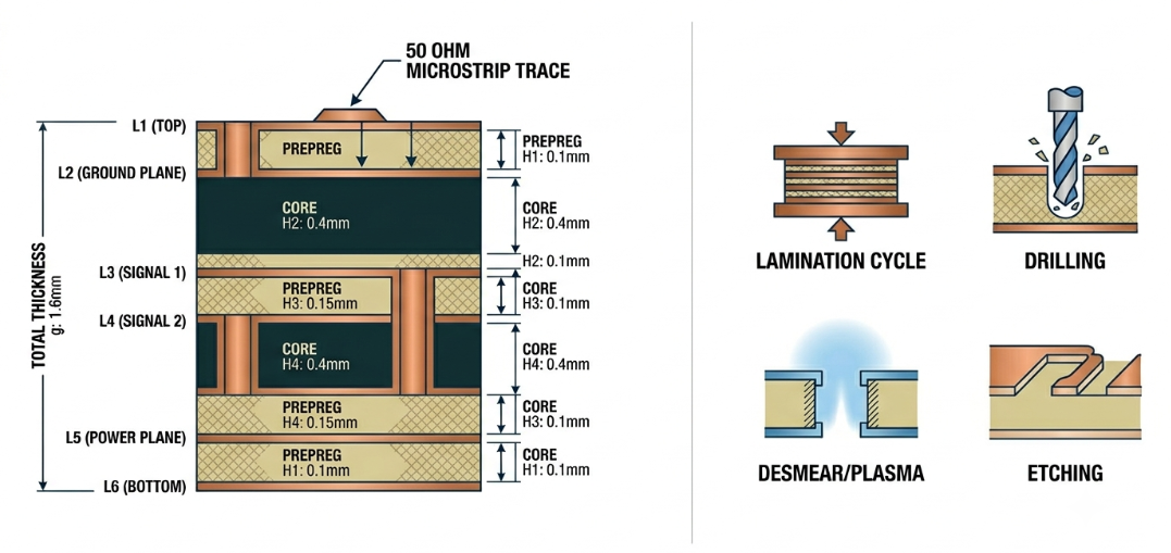
- Lamination cycle: Each resin system requires specific temperature and pressure profiles, and hybrid stacks must share a compatible cycle.
- Drilling: Different feeds and speeds for different materials. Drill bits wear out more quickly on ceramic-filled laminates and Rogers laminates, increasing cost.
- Desmear and hole-wall prep: Plasma chemistry varies with different resins for proper plating.
- Etching: Copper foil profile and thickness influence etching compensation; low thickness (low Rz, 2µm) reduces high-frequency copper loss, but requires careful handling.
Once you leave the realm of common FR4, you're also going to require the fab to change its process, which is where it pays to work with a manufacturer who has a lot of material experience.
JLCPCB's Expertise in PCB Laminate Selection and Fabrication
Selection of Certified High-Performance Laminates
Modern PCB manufacturers, like JLCPCB, have a wide selection of approved laminates from common and high T-Grade FR4 to specialty PCB laminates for use in high-frequency applications, including Rogers and PTFE-based materials. With certified options available, you can look for Dk, Df, and Tg to meet your application without the sourcing hassles. This family allows a designer to seamlessly transition from a low-cost FR4 prototype to a Rogers-based RF board with the same supply chain and with documented material data.
Consistent High-Quality Results from Prototype to Volume Production
Repeatability is the true measure of a laminate strategy. If a board is impedance matched at prototype, the board's impedance specification must remain the same in thousands of boards. Considering the application of these principles, JLCPCB's fabrication services are a convenient way to get from a $2 prototype to volume production with the same laminate properties, impedance, and reliability. The foundation you select remains firm from the first article to mass production, with the production turnaround as quick as 1-2 days and integrated SMT assembly.
FAQ about PCB Laminate
Q: What is a PCB laminate made of?
A PCB laminate is a composite of a reinforcement, usually woven fiberglass cloth, impregnated with a resin system such as epoxy, then cured and bonded with copper foil. When clad with copper, it becomes a copper-clad laminate, the basic building block of every rigid PCB.
Q: When should I move away from standard FR4?
Move to a specialty laminate when your design needs high-speed signal integrity above roughly 5 GHz, survives multiple lead-free reflow cycles, or operates in harsh thermal environments. Low-loss, high-Tg, or high-frequency PCB laminates address the dielectric loss and thermal limits where FR4 struggles.
Q:How does laminate choice affect impedance control?
The laminate's dielectric constant and the pressed dielectric height directly set trace impedance. Because real Dk depends on resin content and prepreg press-out, you must recalculate the stackup whenever you change laminates to keep controlled impedance within tolerance.
Q: What TG should I choose for lead-free assembly?
For lead-free SAC305 reflow with peaks around 245 to 260 °C, choose a high-Tg laminate rated 170 °C or higher. Higher Tg and decomposition temperature reduce Z-axis expansion and protect plated through-holes across multiple thermal cycles.
Q: Are high-frequency laminates harder to manufacture?
Yes, materials like Rogers and PTFE require adjusted lamination cycles, different drilling feeds and speeds, and material-specific desmear chemistry. Ceramic-filled laminates also wear drill bits faster, so partnering with a fabricator experienced across many laminate types ensures consistent, reliable results.
Conclusion
Selecting the right PCB laminate is one of the most critical decisions in achieving a reliable, high-performance circuit board. From standard FR4 for everyday applications to high-Tg, low-loss, and advanced RF materials like Rogers RO4350B or PTFE, your choice directly impacts signal integrity, thermal reliability, impedance control, and long-term product durability. A well-matched laminate ensures your design survives reflow, maintains stable electrical performance across frequencies, and thrives in demanding environments.
By understanding key material properties — Dk, Df, Tg, and CTE — and aligning them with your specific frequency, thermal, and reliability requirements, you can avoid costly failures and optimize both performance and manufacturability. Partnering with an experienced manufacturer like JLCPCB, which offers a wide range of certified laminates and proven fabrication expertise, makes it easier to move seamlessly from prototype to volume production with consistent quality.
Keep Learning
How to Prevent Solder Bridges for Superior PCB Quality and Reliability
Key Takeaways Solder bridges are a leading cause of SMT failures on fine-pitch components. Prevent them with proper solder mask dams (0.075–0.1mm), optimized stencil design, and controlled reflow profiles. Combine good DFM practices with AOI + X-ray inspection for maximum reliability. Professional manufacturing and early DFM review significantly boost first-pass yield and reduce costly rework. You have experienced the post-reflow sadness and eyed the board that failed on the first reflow, if you have ......
How PCB Functional Testing Ensures Your Product Works Flawlessly from Day One
Key Takeaways Looks right doesn’t mean it works right. Only PCB Functional Testing (FCT) verifies real-world performance that structural tests like AOI, ICT, and X-ray cannot catch. JLCPCB’s E-test, AOI, and X-ray ensure zero-defect hardware, so your FCT focuses on design and firmware issues. Design for testability: add clear test points and include a firmware test mode for fast verification. Final Tip: Always perform FCT before shipping — it prevents expensive field failures and builds product confid......
Choosing the Right CTI Value for Safer High-Voltage PCBs
Key Takeaways Higher CTI (≥600V, Group I) allows shorter creepage distances while preventing surface tracking in high-voltage designs. Standard FR4 (CTI ~175V) is often inadequate for mains voltage — upgrade to high-CTI materials for safety and compactness. Always match CTI material group to your working voltage and pollution degree for IEC/UL compliance. Clean assembly and good layout practices are essential to realize the full benefits of high-CTI laminates. Choose certified high-CTI materials and e......
Why Choosing the Right TG Value Leads to More Reliable PCBs
Key Takeaways Tg is key to PCB reliability — it determines when the material loses rigidity under heat. Choose high Tg (≥170°C) for automotive, industrial, or multilayer boards to reduce expansion stress and delamination. Standard Tg (130–140°C) is sufficient for low-power consumer electronics. Higher Tg delivers better thermal stability, especially during lead-free soldering and thermal cycling. Right Tg choice = fewer failures and lower long-term costs. Did you ever question how it's possible for 2 ......
Choosing the PCB Laminate for Reliable High-Performance Boards
Key Takeaways Choosing the right PCB laminate is the foundation of a reliable high-performance board. Match your material to the application — standard FR4 for basic designs under 5 GHz, high-Tg FR4 for lead-free assembly, low-loss materials for high-speed digital, and Rogers/PTFE for RF and mmWave applications. Always prioritize stable Dk, low Df, high Tg, and low Z-axis CTE while recalculating your stackup for accurate impedance control. Partnering with an experienced manufacturer ensures optimal pr......
Mastering BT Resin Packaging: Technical Insights & JLCPCB Capabilities
Key Takeaways BT resin is a high-performance thermoset polymer with Tg of 180°C–210°C, ultra-low Dk/Df, and under 0.05% moisture absorption — essential for advanced IC packaging substrates (BGA, CSP, SiP). Its dense cross-linked structure provides superior resistance to electromigration, dendrite growth, and chemical degradation, making it ideal for fine-pitch, high-reliability applications. Manufacturing BT resin PCBs requires specialized diamond-coated drilling, UV/CO2 hybrid laser systems, and prec......