
LED Sizes Explained: Complete LED Size Chart, Types, Dimensions, and Applications
10 min
- LED Sizes Overview
- SMD LED Sizes
- SMD LED Size Chart
- Most Common SMD LED Packages
- Through-Hole LED Sizes
- SMD vs Through-Hole LEDs
- COB LED Sizes
- LED Chip Size vs LED Package Size
- Mini LED and Micro LED Sizes
- 2835 vs 3528 vs 5050 SMD LED Comparison
- How to Choose the Right LED Size
- Why LED Size Matters
- FAQs on LED Sizes
- Conclusion
LEDs come in multiple package types, and choosing the wrong LED size affects brightness, PCB footprint, thermal performance, and assembly method. Whether you are placing an indicator on a breadboard, designing an LED strip PCB, or specifying a COB module for a spotlight, size is the first decision to get right.
This guide covers every major LED size category, through-hole dimensions, SMD package codes, COB module sizes, and the difference between chip size and package size, with a quick-reference chart for each.
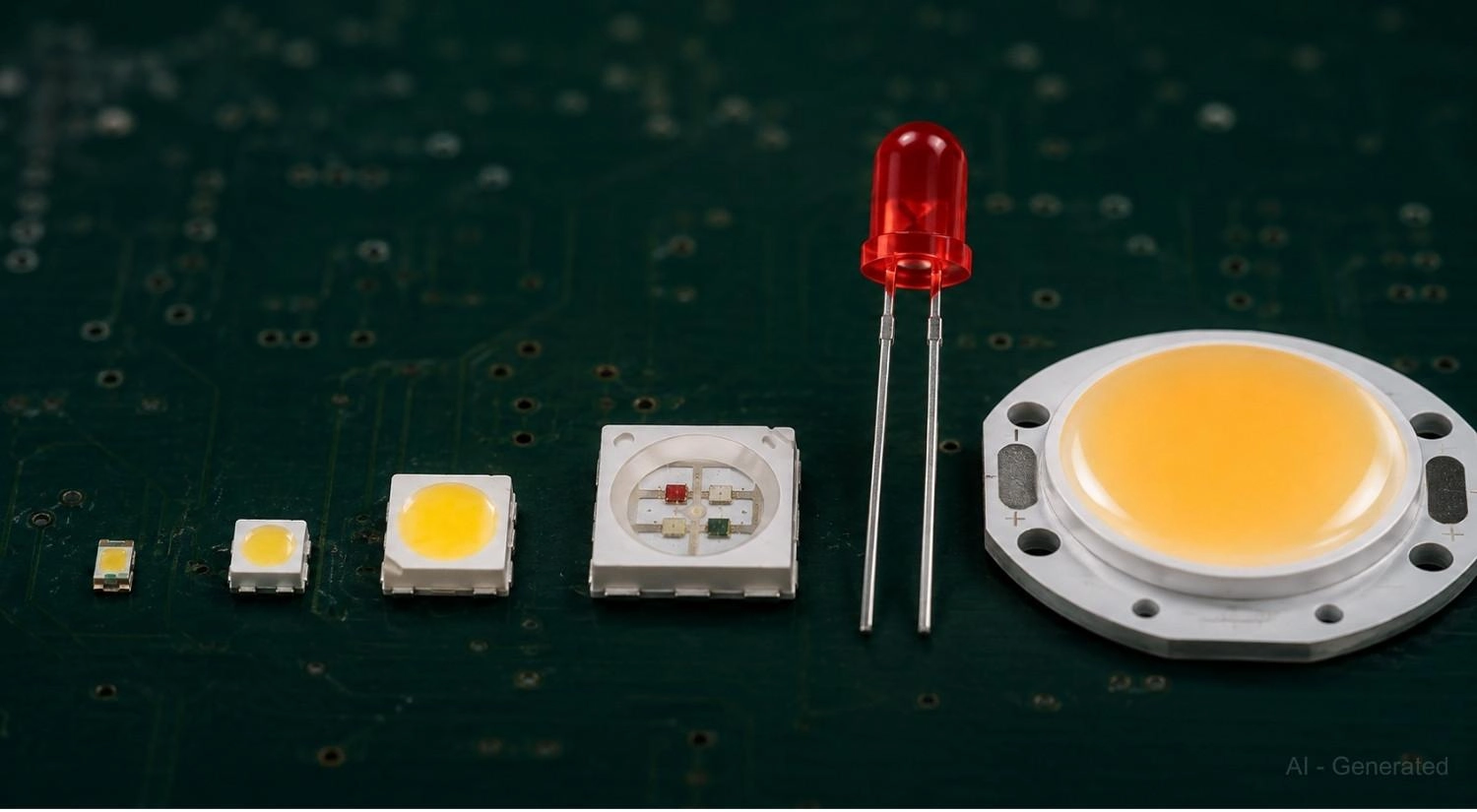
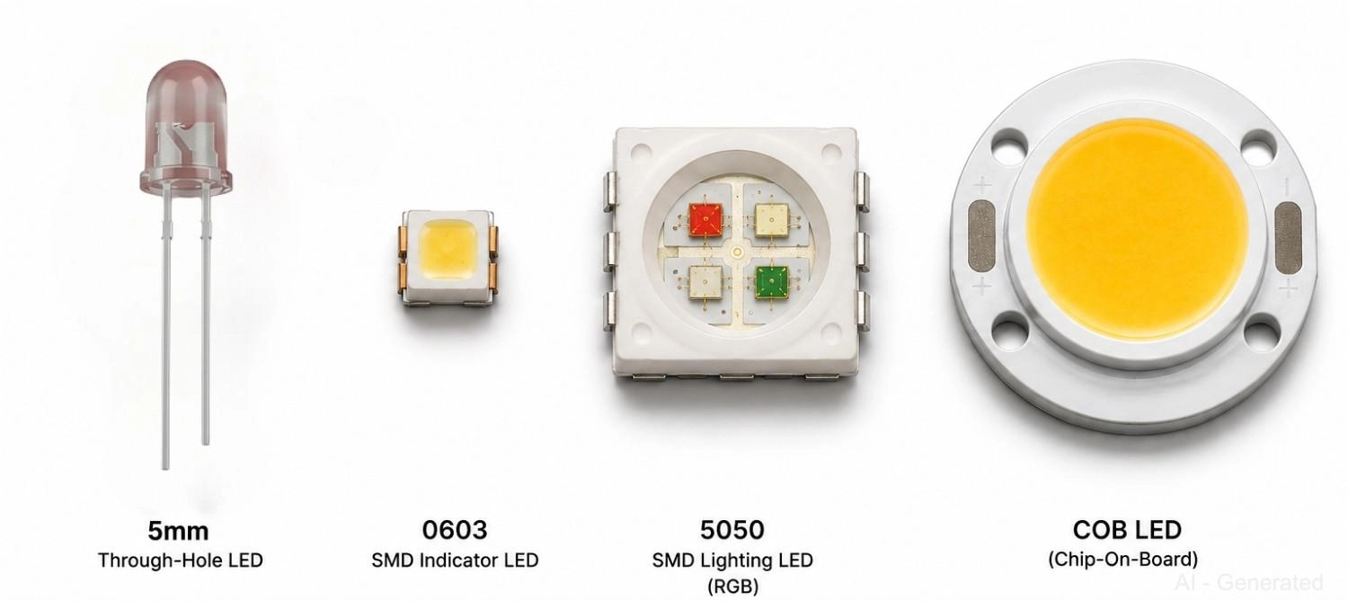
Figure: Showing LED package size progression from 0402 SMD chip through 5050 RGB, 5mm through-hole, and 30mm COB module.
LED Sizes Overview
Quick answer: LED sizes fall into four categories based on package type.
- Through-hole: 3mm, 5mm, 8mm, 10mm, identified by body diameter
- SMD indicators: 0402, 0603, 0805, 1206, footprint encoded in part number (mm)
- SMD lighting: 2835, 3528, 5050, 5630 (for example, 2835 = 2.8 x 3.5 mm)
- COB: 10 to 50+ mm modules, sized by light-emitting surface (LES) diameter
| LED Type | Common Sizes | Main Use |
|---|---|---|
| Through-hole | 3mm, 5mm, 8mm, 10mm | Indicators, DIY, panel mount |
| SMD (indicator) | 0402, 0603, 0805, 1206 | PCB status LEDs, dense layouts |
| SMD (lighting) | 2835, 3528, 5050, 5630 | LED strips, panels, RGB lighting |
| COB | 10 to 50+ mm LES | Spotlights, downlights, floodlights |
| Chip / Micro LED | Less than 1 mm die | Wearables, AR/VR displays |
SMD LED Sizes
SMD LED package codes encode physical dimensions in millimeters. A 2835 is 2.8 x 3.5 mm; a 5050 is 5.0 x 5.0 mm. Two functional tiers: indicator-class for status LEDs and lighting-class for illumination.
Both types support automated PCB assembly via pick-and-place and reflow soldering. Once an SMD LED is selected, the next step is confirming orientation, which is where this SMD LED polarity guide comes in handy for reading cathode markings and footprint indicators across all package sizes.
SMD LED Size Chart
Footprint dimensions feed directly into your solder pad design, so always confirm pad geometry against the manufacturer's datasheet.
| Package | Dimensions (mm) | Height (mm) | Brightness | Best For |
|---|---|---|---|---|
| 0402 | 1.0 x 0.5 | 0.35 | Very low | Dense layouts, wearables (automated only) |
| 0603 | 1.6 x 0.8 | 0.45 | Low | Compact PCB indicators |
| 0805 | 2.0 x 1.25 | 0.55 | Low to medium | Standard indicator, hand-solderable |
| 1206 | 3.2 x 1.6 | 0.65 | Medium | Easy-solder indicator, low-volume builds |
| 2835 | 2.8 x 3.5 | 0.70 | High | LED strips, panels, white lighting |
| 3528 | 3.5 x 2.8 | 1.90 | Medium | Decorative strips (legacy) |
| 5050 | 5.0 x 5.0 | 1.60 | Very high | RGB lighting, addressable strips |
5630/ 5730 | 5.6 x 3.0 | 0.90 | Ultra-high | Commercial and flood lighting |
| 3030 | 3.0 x 3.0 | 0.80 | High | High-power arrays need MCPCB |
Note: Dimensions are nominal. Always verify pad layout and Vf against the component datasheet before finalizing your PCB footprint.
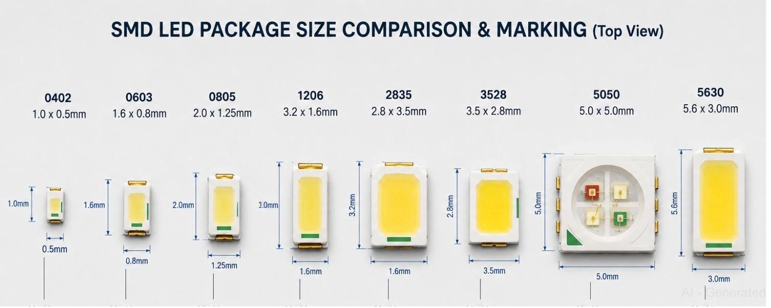
Figure: SMD LED package scale comparison showing eight packages from 0402 to 5630
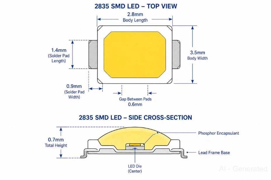
Figure: 2835 SMD LED showing top-view dimensions (2.8 x 3.5mm body, 0.9 x 1.4mm pads) and side cross-section with 0.7mm total height, die, and encapsulant.
Most Common SMD LED Packages
0603 LEDs
- 1.6 x 0.8 mm; 0.45 mm tall
- Best for PCB status indicators on compact boards
- Requires automated pick-and-place; not reliably hand-solderable
2835 LEDs
- 2.8 x 3.5 mm; best lumens-per-watt of any mainstream SMD package
- Slim 0.70 mm profile suits LED strips and panel lights
- Standard in modern LED PCB manufacturing, available through JLCPCB's parts library and supported by JLCPCB's PCB assembly service
3528 LEDs
- 3.5 x 2.8 mm; older standard still found in budget decorative strips
- Lower efficiency than 2835; not recommended for new designs
5050 LEDs
- 5.0 x 5.0 mm; three-die package enables RGB color-mixing in a single component
- Standard for addressable strips (WS2812B, SK6812) and architectural color lighting
Through-Hole LED Sizes
Through-hole LEDs are sized by body diameter. Lead pitch is 2.54 mm (100 mil) across all standard sizes. The longer lead is the anode.
| LED Size | Body Diameter | Approx. Height | Best For |
|---|---|---|---|
| 3mm (T-1) | 3.0 mm | 5.0 mm | Compact indicators, hobby breadboards |
| 5mm (T-1¾) | 5.0 mm | 8.6 mm | Prototyping, panel mount, education |
| 8mm | 8.0 mm | 10.0 mm | Signage, decorative displays |
| 10mm | 10.0 mm | 12.0 mm | Large panels, outdoor indicators |
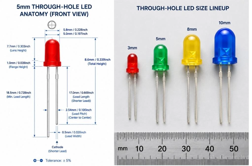
Figure: Through-hole LED showing 5mm LED with key dimensions labeled, and size lineup showing 3mm through 10mm LEDs to scale with ruler.
SMD vs Through-Hole LEDs
For a deeper comparison of the two mounting methods beyond LEDs alone, see this guide on surface-mount vs through-hole assembly.
| Feature | Through-Hole | SMD |
|---|---|---|
| Assembly | Hand soldering | Automated pick-and-place |
| PCB Density | Low | High |
| Brightness Density | Low | High |
| Prototyping | Excellent | Moderate |
| Mass Production | Largely obsolete | Industry standard |
| Viewing Angle | 15 to 60 degrees | 120 to 160 degrees |
COB LED Sizes
A COB (Chip-on-Board) LED bonds multiple dies directly onto a substrate under a uniform phosphor layer. COBs are sized by LES (Light-Emitting Surface) diameter, not a footprint code.
| COB Type | LES Diameter | Application |
|---|---|---|
| Small | 6 to 20 mm | Spotlights, retail accent lighting |
| Medium | 20 to 40 mm | Downlights, track lighting |
| Large | 50 mm and above | Floodlights, high-bay, horticultural |
Key points:
- COB LES size varies by manufacturer; no universal naming standard
- Require a dedicated heatsink and thermal interface material
- Not assembled on FR4 PCBs; distinct from SMD workflows
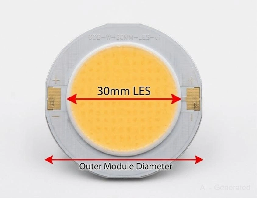
Figure: COB LED module with red dimension arrow labeling 30mm LES diameter
LED Chip Size vs LED Package Size
The package size is the outer housing: lead frame, lens, encapsulant, and PCB pads. It is what part numbers like 0603, 2835, and 5050 describe.
Chip (die) size is the internal semiconductor die. Standard LEDs typically have a 250 to 500 µm die inside any given package.
Two LEDs with the same package code can have different die sizes, affecting efficiency, flux output, and color consistency. Package size reflects footprint. Die quality reflects performance.
Mini LED and Micro LED Sizes
Mini LED and Micro LED are emerging package categories driven by display technology.
- Mini LED: die size typically below 200 µm; used in backlighting for LCD TVs and monitors with local dimming zones
- Micro LED: die size below 100 µm; used in AR/VR headsets, smartwatches, and high-resolution direct-view displays
Neither type follows standard SMD package naming; sizes are defined by pixel pitch (sub-1 mm) and die transfer method rather than a footprint code
These differ from standard SMD and COB LEDs in the manufacturing process and are not sourced from conventional parts libraries.
2835 vs 3528 vs 5050 SMD LED Comparison
| Feature | 2835 | 3528 | 5050 |
|---|---|---|---|
| Dimensions | 2.8 x 3.5 mm | 3.5 x 2.8 mm | 5.0 x 5.0 mm |
| Height | 0.70 mm | 1.90 mm | 1.60 mm |
| Efficiency | High | Medium | Medium |
| RGB Support | No | No | Yes (3-die) |
| Brightness | High | Lower | Very high |
| Board Space | Low | Low | High |
| Best For | White strips, panels | Decorative/legacy | RGB color lighting |
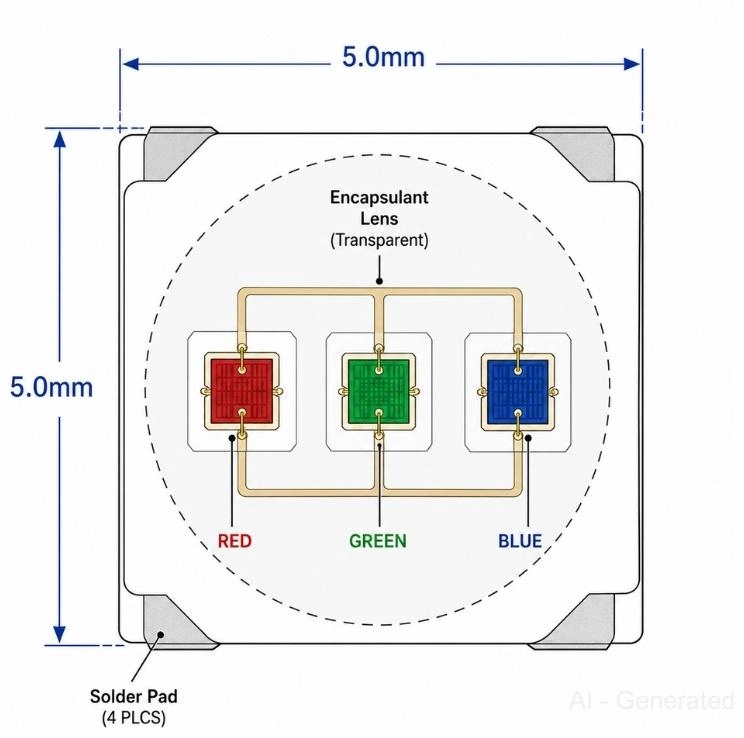
Figure: 5050 SMD LED internal layout diagram showing red, green, and blue dies inside a 5.0 x 5.0mm package with four corner solder pads and dimension labels.
How to Choose the Right LED Size
Check the LED selection quick-reference table
| If You Need | Recommended LED |
|---|---|
| Breadboard or prototype | 5mm through-hole |
| Panel-mount indicator | 5mm through-hole |
| Tiny PCB indicator (hand solder) | 0805 or 1206 |
| Tiny PCB indicator (automated) | 0603 or 0402 |
| Efficient white LED strips | 2835 |
| RGB or color-changing strips | 5050 |
| High-power commercial lighting | 5630, 5730, or COB |
| Wearables or AR/VR displays | Micro LED |
LED Assembly method
- Hand soldering: 5mm THT, 0805, 1206
- Low-volume SMT: 0805, 1206, 2835
- High-volume production: any standardized SMD package
Thermal requirements
- Low-power indicators (0402 to 1206): standard FR4, no extra treatment needed
- Mid-power (2835, 5050): copper pours beneath thermal pad; add thermal vias for better transfer
- High-power (5630, 3030, COB): aluminum-core PCB (MCPCB) or dedicated heatsink required
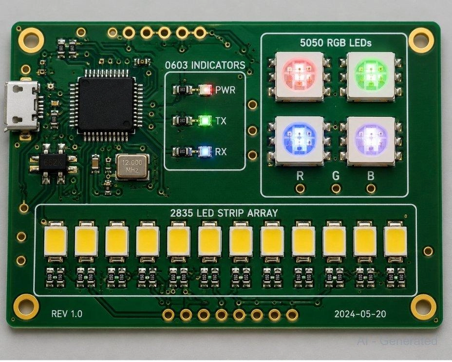
Figure: Populated PCB showing three LED package zones: 0603 indicators near a microcontroller, a 2835 linear strip array, and a 5050 RGB LED cluster in the corner.
Why LED Size Matters
An LED size refers to the physical dimensions of the LED package, measured either by body diameter (for through-hole LEDs) or by footprint code in millimeters (for SMD LEDs like 2835 or 5050). The size determines how the LED is mounted, how much light it can produce, and how it integrates into a PCB design.
LED size is not just a matter of footprint. It directly affects how your design performs and how it gets built.
- Brightness: Larger packages typically support higher drive currents and higher lumen output
- PCB space: Package footprint determines how many LEDs fit on a board and how dense your layout can get
- Thermal performance: Higher-power packages need copper pours, thermal vias, or an aluminum-core PCB (MCPCB) to stay within the rated junction temperature
- Viewing angle: Through-hole packages focus light tightly (15 to 60 degrees); SMD packages spread it wide (120 to 160 degrees)
- Assembly method: Sub-0805 packages cannot be reliably hand-soldered and require automated pick-and-place equipment
- Cost: Smaller indicator packages are cheaper per unit at volume; high-power packages cost more and require more elaborate PCB substrates
Getting the size right at the design stage avoids the most common LED-related rework: insufficient brightness, overheating, or assembly failures on tight pitches.
FAQs on LED Sizes
Q: What is the most common LED size?
For through-hole: 5mm (T-1¾). For SMD lighting: 2835. For SMD indicators: 0603.
Q: What do numbers like 2835 and 5050 mean?
They encode physical dimensions in mm. A 2835 is 2.8 x 3.5 mm. A 5050 is 5.0 x 5.0 mm. The same logic applies to every SMD LED package code.
Q: Is 2835 better than 3528?
Yes, for most modern designs. The 2835 offers higher lumens-per-watt and a slimmer 0.70 mm profile. The 3528 is a legacy package still found in budget strip products.
Q: Which LED is easiest to solder?
A 5mm through-hole is easiest to hand-solder. For SMD, 0805 and 1206 work with a standard iron. Packages below 0805 need automated equipment.
Q: What LED should I use for a PCB indicator?
0603 with automated SMT, 0805 or 1206 for hand soldering, 3mm or 5mm THT for panel-mount builds.
Q: What is a COB LED?
A COB (Chip-on-Board) LED bonds multiple dies onto one substrate under a phosphor layer. Sized by LES diameter (6 to 50+ mm). Used in spotlights, downlights, and floodlights, not on standard PCBs.
Q: What is the difference between Mini LED and Micro LED?
Mini LEDs have dies below 200 µm and are used for LCD backlight dimming. Micro LEDs are below 100 µm and target direct-view displays in AR/VR and wearables. Neither uses standard SMD footprint codes.
Conclusion
LED size selection comes down to board space, brightness, assembly method, and thermal needs. The 5mm through-hole and 2835 SMD cover the majority of common builds. For RGB use 5050; for high-output illumination use COB or 5630/5730.
Popular Articles
• SMD Capacitor Sizes: Complete Size Chart and Selection Tips for PCB Design and Assembly
• SMD Diode Code Lookup: Full List, Marking Guide & Identification [2026 Guide]
• SMD Resistor Package Sizes: Complete Size Chart, Footprints & How to Choose
• SMD Capacitor Codes: Identification, Markings, and Polarity
• How to Solder SMD Components Like a Pro [2026 Updated]
Keep Learning
Thin Film vs. Thick Film Resistors: Key Differences, Advantages & Applications
Key Takeaways Default to thick film resistors for most designs. They are cost-effective, robust, and ideal for pull-ups, LED current-limiting, digital circuits, and surge-prone applications. Choose thin-film resistors whenever a resistor defines an analog quantity, such as a voltage divider, reference network, gain-setting circuit, or current-sensing signal chain. Their tight tolerance and low TCR help maintain measurement accuracy over temperature and time. Most PCB designs use thick film or thin fil......
What Is the ESP32? A Complete Guide to Features, Architecture, Modules, Programming, and Applications
From Wi-Fi-enabled temperature sensors and wearable health monitors to industrial gateways and AI-powered cameras, the ESP32 microcontroller has become one of the world's most widely adopted wireless embedded platforms. Combining a powerful processor with integrated Wi-Fi and Bluetooth, it lets engineers build connected devices without separate networking hardware. This guide covers ESP32 specifications, architecture, the full family of variants, development boards, programming tools, and real-world E......
How to Choose the Right STM32 Microcontroller: Compare Series, Cortex-M Cores, and Key Features
STMicroelectronics ships thousands of STM32 MCU part numbers across more than a dozen series, and that variety is exactly what makes STM32 microcontroller selection difficult. Pick the wrong family, and you pay for it later: oversized BOM cost, wasted power budget, or a board respin when a peripheral turns out to be missing. This STM32 microcontroller selection guide breaks the decision into a five-step framework built on practical engineering criteria, not datasheet marketing copy, so you can match a......
SMD Transistor Code Lookup: Identify Markings, Pinout & Multimeter Test Guide
Repairing a circuit board often brings a familiar frustration: staring at a tiny, three-legged black component with an obscure two- or three-letter code. Whether troubleshooting a bare prototype or a mass-produced PCBA, knowing how to quickly decode these surface-mount device (SMD) markings is an essential skill for any electronics engineer or repair technician. In this comprehensive guide, you will learn: 1. How to decode SMD transistor marking codes 2. How to identify BJT vs MOSFET types 3. How to f......
SMD Capacitor Sizes: Complete Size Chart and Selection Tips for PCB Design and Assembly
In the world of modern electronics, surface mount devices (SMDs) have revolutionized board design, allowing for smaller, faster, and more efficient printed circuit boards. When designing a PCB, selecting the correct SMD capacitor sizes is one of the most critical decisions an engineer must make to ensure both electrical reliability and manufacturability. In this article, you will find practical, authoritative guidance on: Comprehensive SMD capacitor size charts for quick reference. How to read imperia......
SMD Diode Code Lookup: Full List, Marking Guide & Identification [2026 Guide]
In modern electronics, surface-mount diodes are used everywhere - from power input protection circuits to high-speed signal routing. Because these components are extremely small, manufacturers cannot print full part numbers on their bodies. Instead, they use short marking codes such as A2, M7, SS14, or SL, which often confuse beginners during PCB repair, reverse engineering, or component replacement. This guide explains how to decode SMD diode codes, identify polarity, test components using a multimet......