
The Ultimate Guide to Testing Diodes: Multimeter Settings, Readings, and Diagnosis
15 min
- Diode Polarity: How to Identify the Anode and Cathode
- How to Test a Diode With a Multimeter (Diode Test Mode)
- How to Read Diode Test Results
- Forward Voltage Drop by Diode Type
- How to Test Different Types of Diodes
- Diode Test Mode vs Resistance Mode vs Continuity Mode
- Testing a Diode In-Circuit vs Out-of-Circuit
- How to Tell If a Diode Is Bad
- FAQs on Diode Testing
- Conclusion
Quick Answer: How to Test a Diode
To check a diode with a multimeter, set the device to diode test mode.
Put the red probe on the anode and the black probe on the cathode.
A healthy silicon diode provides a good diode reading of 0.5V to 0.8V in forward bias and OL (Open Loop) in reverse bias.
Knowing how to tell if a diode is bad is simple: OL both ways indicates an open diode, while a near-zero voltage reading both ways indicates a shorted diode.
Knowing how to test a diode is one of the fastest ways to troubleshoot a faulty power supply, malfunctioning circuit, or PCB that won't power on. Using a digital multimeter, you can quickly determine whether a diode is working properly, shorted, or open.
This guide covers how to set your multimeter to diode test mode, read forward-bias and reverse-bias values, tell a good diode from an open or shorted one, test in-circuit versus out-of-circuit, and handle specific types: rectifier, Schottky, Zener, LED, and bridge rectifier.
Diode Polarity: How to Identify the Anode and Cathode
Understanding diode polarity is the first step in successful diode testing:
- Current Direction: Current flows from the anode (positive terminal) to the cathode (negative terminal) in forward bias.
- Physical Markings: The printed stripe or band on a physical axial diode marks the cathode side. On surface-mount diodes, look for a small bar or laser-etched line.
- Schematic Symbol: The symbol consists of a triangle pointing toward a vertical bar. The triangle represents the anode, and the vertical bar represents the cathode. You can learn more about identifying these layouts in this detailed diode symbol guide.
- Light Emitting Diodes (LEDs): For through-hole LEDs, the longer leg is the anode, while the shorter leg and the flat edge of the plastic casing mark the cathode. For SMD versions, check the manufacturer's polarity markings or refer to an SMD LED polarity guide to avoid reverse placement during assembly.
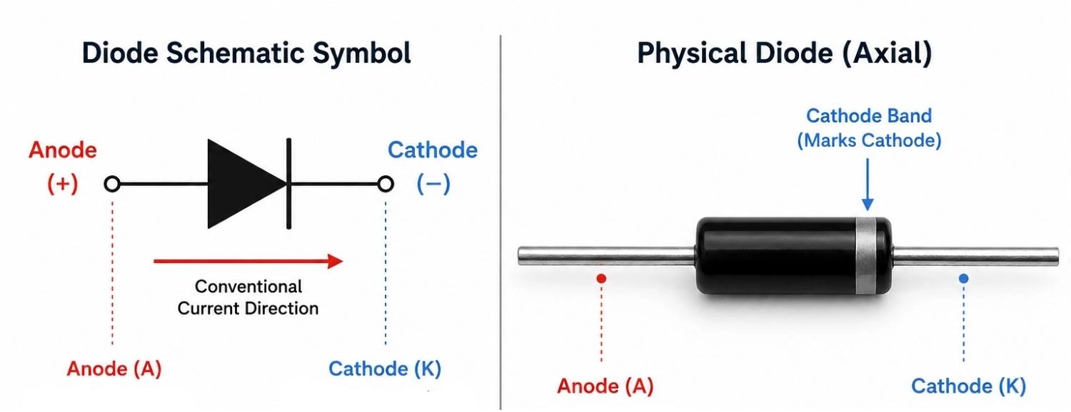
Figure: Diode schematic symbol and physical component showing anode, cathode, and the cathode band.
How to Test a Diode With a Multimeter (Diode Test Mode)
Using the diode test mode is the most reliable diagnostic method. The multimeter pushes a small constant current (typically 1 mA to 2 mA) through the diode and measures the resulting forward voltage drop across its terminals.
Step 1: Turn Off Power and Discharge Capacitors
Safety is paramount. Ensure the device under test is completely powered down. Unplug any power cords and remove batteries. Discharge any large electrolytic or power supply filter capacitors using an appropriate discharge tool. Charged capacitors hold dangerous voltage, introduce false readings, and can damage your meter.
Step 2: Set the Multimeter to Diode Mode
Turn the selection dial to the diode symbol (represented by a triangle pointing to a vertical bar). On many digital multimeters, this position shares a spot with resistance or continuity modes. If so, press the "Select" or "Shift" function button on your meter until the diode icon appears on the LCD screen.
Step 3: Connect the Red Probe to the Anode
Plug the red test probe into the "V-Omega-Diode" jack of the multimeter. Touch the tip of this red (positive) probe to the anode terminal of the diode.
Step 4: Connect the Black Probe to the Cathode
Plug the black test probe into the "COM" (common/ground) jack. Touch the tip of this black (negative) probe to the cathode terminal of the diode (marked by the stripe). This biases the PN junction forward, allowing current to flow.
Step 5: Read the Forward Voltage Drop
Observe the value on the screen. A healthy silicon diode multimeter reading will display a diode forward voltage drop between 0.5V and 0.8V.
Step 6: Reverse the Probes
Keep the meter in diode mode and swap the positions of the probes. Touch the red probe to the cathode and the black probe to the anode. This places the diode in reverse bias, which should block all current. A functioning diode must display OL (Open Loop or Over Limit) on the screen.
Step 7: Interpret the Results
Compare your measured readings with standard semiconductor performance values.
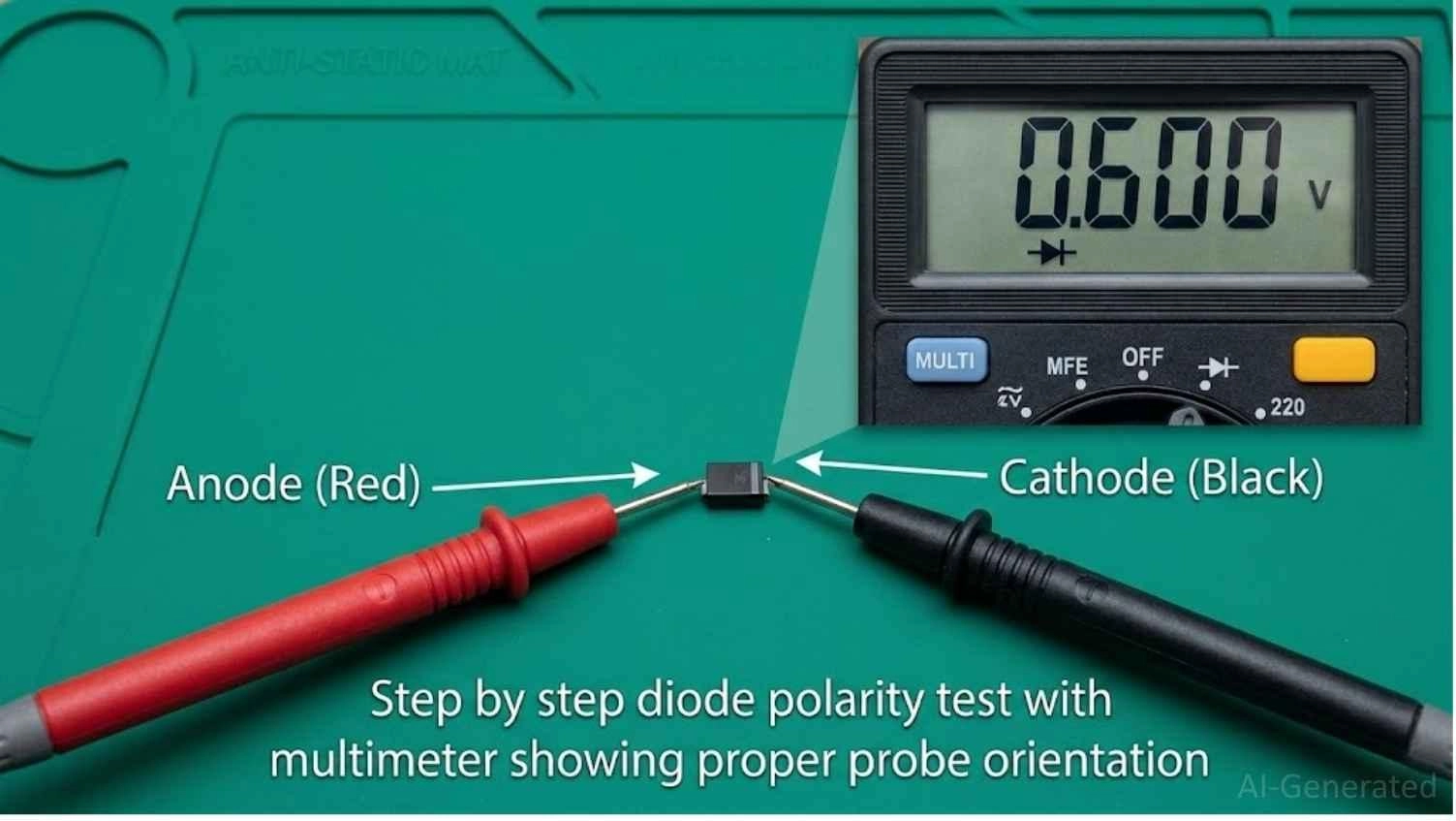
Figure: Multimeter in diode test mode with red probe on anode and black probe on cathode showing 0.6V.
How to Read Diode Test Results
When analyzing a diode, the combination of forward and reverse readings tells the whole story.
| Condition | Forward Bias Reading (Red to Anode) | Reverse Bias Reading (Red to Cathode) | Component Verdict |
|---|---|---|---|
| Good Silicon Diode | 0.5V to 0.8V | OL | Good (Passes current one way) |
| Open Diode | OL | OL | Faulty (Open circuit junction) |
| Shorted Diode | 0V to 0.4V (often near 0.00V) | 0V to 0.4V (often near 0.00V) | Faulty (Fused junction) |
| Leaky Diode | Normal (0.5V to 0.8V) | Measurable voltage drop (less than OL) | Faulty (High reverse leakage) |
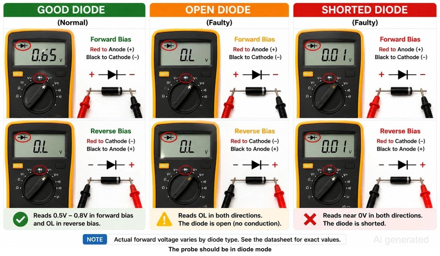
Figure: Multimeter readings comparing good, open, and shorted diodes in forward and reverse bias.
Tech Tip:
If your in-circuit readings are confusing or borderline, remove the component from the board before concluding. Nearby components, such as low-value resistors or inductor coils, can bypass the diode and trick your meter.
When sourcing components or looking up technical parameters, check the JLCPCB Parts Library for accurate component datasheets.
What Does OL Mean on a Diode Test?
On a digital multimeter, OL stands for "Open Loop" or "Over Limit". This reading indicates that the resistance is too high for the meter to measure, or that no electric current is flowing between them.
In a diode test, seeing OL in the reverse-bias direction is the expected behavior of a healthy semiconductor. However, seeing OL in the forward-bias direction means the internal junction has broken open, and the diode is dead.
Forward Voltage Drop by Diode Type
Not all diodes are made of silicon. Different materials and architectures have different forward voltage drops (V_f).
| Diode Type | Typical Forward Voltage Drop | Common Uses |
|---|---|---|
| Silicon Diode | 0.6V to 0.7V | General purpose rectification, signal clamping |
| Germanium Diode | 0.2V to 0.3V | RF detection, vintage audio circuits |
| Schottky Diode | 0.15V to 0.45V | High-frequency switching, power supplies |
| Red LED | 1.8V to 2.2V | Visual indicators, optocouplers |
| Blue / White LED | 3.0V to 3.5V | Backlighting, high-brightness indicators |
| Zener Diode (forward) | ~0.7V | Voltage regulation (standard forward direction) |
| Rectifier Diode | ~0.7V | High-current power rectification (e.g., 1N4007) |
Note
Forward voltage values are temperature and current dependent. Always check the manufacturer's datasheet when troubleshooting critical circuits.
How to Test Different Types of Diodes
#1 How to Test a Rectifier Diode
Rectifier diodes like the popular 1N4007 series are robust components. Use the standard diode-mode test:
- Forward Bias: Place red on the anode and black on the cathode (stripe). You should read roughly 0.5V to 0.7V.
- Reverse Bias: Swap the leads. You must see OL. Any voltage reading in reverse means the rectifier is damaged.
#2 How to Test a Schottky Diode
Schottky diodes feature a metal-to-semiconductor junction, resulting in high switching speeds and a much lower forward voltage drop.
- Forward Bias: Expect a reading between 0.15V and 0.45V. Do not mistake this low voltage drop for a partial short-circuit.
- Reverse Bias: Swap the leads. The reading must be OL.
#3 How to Test a Zener Diode
Testing a Zener diode requires a two-part approach because standard multimeters cannot supply enough reverse voltage to reach its breakdown point:
- Forward Test: Use standard diode mode. A good Zener reads around 0.7V in forward bias and OL in reverse bias. This only confirms that the diode is not shorted or open.
- Reverse Voltage Test: To verify if the Zener clamps at its rated breakdown voltage (V_z), build a simple test circuit. Connect an external DC power supply (set higher than V_z) in series with a 1k-ohm resistor to the Zener's cathode, and connect the anode to ground. Measure the DC voltage directly across the Zener diode. A healthy 5.1V Zener diode will show a steady reading of roughly 5.1V.
#4 How to Test an LED With a Multimeter
Because Light Emitting Diodes have a higher forward voltage drop (V_f), the multimeter's diode mode must output enough voltage to bias them:
- Forward Bias: Red probe to anode, black to cathode. The LED should emit a faint glow, and the meter will display its forward voltage (e.g., ~1.8V for red, ~3.2V for blue).
- Reverse Bias: Swap the leads. The LED should remain dark, and the screen should display OL.
- Note: Budget multimeters with a diode test voltage below 3V may not be able to light up blue, green, or white LEDs.
#5 How to Test a Bridge Rectifier Diode
A bridge rectifier package integrates four diodes in a bridge configuration. To test it, treat the package as four individual diodes:
- Locate the four pins: two AC input pins (marked with ~), a positive output pin (+), and a negative output pin (-).
- Test each of the four internal diodes using standard diode mode.
- Measure from the AC pins to the positive (+) pin, and from the negative (-) pin to the AC pins.
- You should read a standard forward voltage drop (~0.5V to 0.8V) in the forward direction and OL in the reverse direction for all four internal junctions.
- Measuring directly across the + and - pins will read around 1.0V to 1.4V in one direction (since current passes through two diodes in series) and OL in the other. A shorted reading between any pin pair indicates a failed rectifier.
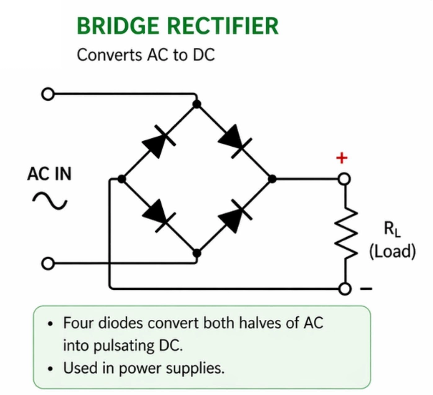
Figure: Bridge rectifier diode layout with AC, positive, and negative terminals labeled for testing.
Diode Test Mode vs Resistance Mode vs Continuity Mode
Using the wrong multimeter mode can lead to incorrect diagnoses. Let's compare the three common options.
| Multimeter Mode | Best For | Technical Limitations |
|---|---|---|
| Diode Mode | Full semiconductor health check | Requires manual reading analysis |
| Resistance Mode | Checking for direct shorts | Low voltage cannot bias the PN junction reliably |
| Continuity Mode | Fast short-circuit detection | No forward-voltage drop data provided |
Why Diode Test Mode Gives the Most Accurate Results
Diode test mode is the gold standard because it supplies a dedicated voltage of up to 2.0V or 3.0V. This voltage is high enough to overcome the barrier potential of the PN junction, allowing the meter to show the exact forward voltage drop.
Testing a Diode in Resistance Mode: Why It Falls Short
Performing a diode resistance test (Ohms) uses a very low voltage that is often too weak to fully turn on a semiconductor junction.
- Behavior: A good diode may show a high or unstable resistance in the forward direction and OL in the reverse direction.
- Reliability: Because the test voltage varies widely between different multimeter models, resistance readings are inconsistent and do not represent the diode's true forward-bias voltage drop. Use resistance mode primarily to confirm a suspected direct short (which will read close to 0 ohms in both directions).
Testing a Diode With Continuity Mode: Limitations to Know
Continuity mode is designed for a quick "yes or no" check on wiring.
- Behavior: Some meters beep when testing a diode in the forward direction, while others remain silent because the diode's forward voltage prevents the continuity threshold (often below 30 to 50 ohms) from being met.
- Reliability: Continuity mode does not provide any forward-voltage information. While a continuous beep in both directions reliably highlights a shorted diode, the mode cannot identify an open or leaky diode.
Testing a Diode In-Circuit vs Out-of-Circuit
When In-Circuit Diode Testing Is Reliable
To test a diode in circuit components while they are still soldered to a printed circuit board is a great way to do a quick check. If a diode has a catastrophic failure, this fault will usually show up clearly even when the component is in-circuit.
Why In-Circuit Diode Tests Give False Readings
In-circuit testing often yields false positives or false negatives because of other components in the circuit:
- Alternate Current Paths: If a resistor is connected in parallel with the diode, the multimeter’s current will flow through both paths. This lowers the forward voltage reading and prevents the meter from showing a clean OL in reverse bias.
- Inductive Loads: A flyback diode connected across a relay coil or DC motor winding will show a near-short reading in reverse bias because the meter measures the low DC resistance of the copper coil.
These interactions are particularly common when troubleshooting freshly assembled circuits or custom prototypes. If you are verifying a newly built board, such as one assembled using a low-volume PCB assembly service, parallel paths can easily mask issues or lead you to replace perfectly good parts.
How to Isolate a Diode Lead for an Accurate Out-of-Circuit Test
If you get a suspicious or borderline reading in-circuit, you must isolate the diode:
- Heat one of the diode's solder joints using a soldering iron.
- Gently lift that lead out of the PCB pad using tweezers or a solder sucker.
- Let the joint cool, then test the isolated diode. This isolated reading is 100% accurate.
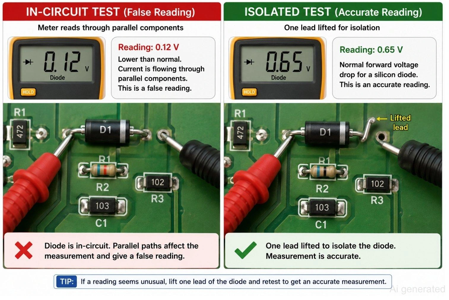
Figure: In-circuit versus isolated diode testing with one lead lifted for an accurate reading.
How to Tell If a Diode Is Bad
A diode is faulty if it exhibits any of the following symptoms during testing:
- Reads OL in both directions: The internal junction has failed and is open.
- Reads near 0V in both directions: The internal junction is fused and shorted.
- Shows a voltage drop in reverse bias: The PN junction is leaky, allowing backward current.
- Inconsistent readings: The reading jumps around erratically, indicating a cracked semiconductor die or a broken bond wire inside the packaging.
Common Diode Failure Modes
Semiconductors fail due to overcurrent, voltage spikes, thermal stress, or aging. There are three main ways a diode fails:
- Open: The internal PN junction is physically severed or blown. It blocks current in both directions, rendering it completely non-functional.
- Shorted: The internal junction has fused together under high current or voltage. It behaves like a low-resistance wire, conducting freely in both directions.
- Leaky: The PN junction is damaged but not completely shorted. It conducts normally in the forward direction but fails to block fully in reverse, letting a small, measurable current leak backward.
| Multimeter Symptom | Likely Failure Cause | Troubleshooting Step |
|---|---|---|
| OL in both directions | Open junction | Replace the diode. |
| Near 0V in both directions | Shorted junction | Replace the diode; check for upstream overcurrent. |
| Reverse voltage drop detected | Leaky junction | Replace the diode to prevent reverse leakage current. |
| Erratic or jumping display | Damaged packaging or junction | Check lead connections; replace diode if erratic behavior continues. |
| Different values in-circuit vs isolated | Parallel circuit path interference | Lift one lead of the diode and retest to confirm. |
FAQs on Diode Testing
Q: How do you know if a diode is bad?
A diode is bad if it conducts in both directions (shorted), blocks in both directions (open), or allows current to pass in reverse bias (leaky). A healthy silicon diode must display a forward voltage drop between 0.5V and 0.8V and show OL in reverse bias.
Q: Can you test a diode while it is still in a circuit?
Yes, you can do a quick check in-circuit. A direct short will usually show up clearly. However, parallel components like resistors, inductors, or capacitors can cause false readings. If you suspect an issue, desolder and lift one leg of the diode to isolate it before taking a final measurement.
Q: Can a multimeter damage a diode?
No. In diode mode, a digital multimeter only outputs a low, current-limited test voltage (usually under 3V and less than 2 mA). This is far below the breakdown threshold or maximum forward current rating of standard semiconductor components, making the test completely safe.
Q: Why does my diode show a different reading each time?
Unstable readings are usually caused by poor contact between the probe tips and the component leads, oxidation on the diode terminals, or loose test leads. If you are testing in-circuit, nearby capacitors discharging can also cause shifting values. Clean the contacts and retest.
Q: Can a diode fail intermittently?
Yes. Thermal expansion, mechanical stress, or a microscopic crack in the semiconductor die can cause a diode to test normal when cold, but fail open or shorted once the circuit warms up under load. If you suspect an intermittent fault, retest the diode immediately after running the circuit.
Q: What is the difference between diode mode and continuity mode?
Diode mode outputs enough voltage to overcome the semiconductor's PN junction barrier and displays the exact forward voltage drop in volts. Continuity mode is used to check for low resistance (under 30 to 50 ohms) and only sounds a buzzer without showing semiconductor voltage characteristics.
Conclusion
Successfully learning how to check a diode comes down to one simple habit: use diode test mode, test in both directions, and compare the readings.
A good diode reading for silicon shows 0.5V to 0.8V forward and OL reverse. Open and shorted parts are easy to spot once you know how to tell if a diode is bad, and lifting one lead resolves any suspicious results when you test diode in circuit.
Component type matters too, so expect lower voltage drops on Schottky diodes and use an external reverse-bias circuit to verify Zener breakdown voltages.

- Verifying your diodes before and after assembly is the best way to supercharge your debugging and troubleshooting process!
- For your next build, skip the hassle and source premium, pre-tested components directly from the JLCPCB Parts Library. Get an instant, hassle-free online quote for professional PCB fabrication and assembly
Popular Articles
• How to Create a Bluetooth-Controlled Car With Arduino: A Step-by-Step Guide
• How to Design and Assemble a Reliable ESP32 Module PCB on a 2-Layer Board
• The Ultimate Guide to Relay Symbol: Coil, Contacts, Diagrams, and Circuit Applications
• How to Identify SMD LED Polarity: Markings, Testing, and PCB Tips
• The Ultimate Guide to PCBA: Process,Types and Techniques for the Electronics Enthusiast
Keep Learning
Arduino LED Driver Tutorial: Control More LEDs with 74HC595 and MAX7219
Arduino GPIO pins run out quickly in larger LED projects. By utilizing dedicated LED drivers and expansion ICs, you can drastically reduce pin usage, eliminate processor-heavy multiplexing loops, and simplify display wiring. In this guide, you will learn the operational architecture, wiring configurations, cascading techniques, and optimization strategies for the 74HC595 shift register and the MAX7219 LED driver. Why Arduino Projects Need LED Driver ICs Arduino GPIO and Current Limitations An ATmega32......
How to Create a Bluetooth-Controlled Car With Arduino: A Step-by-Step Guide
This tutorial walks through the complete engineering and implementation of a two-wheel Bluetooth RC car with an Arduino Nano module on a specially designed PCBA (Printed Circuit Board Assembly). While many hobbyists start by wiring motors and Bluetooth modules with jumper cables on a breadboard, this approach is prone to disconnection and signal noise. This guide upgrades that process by teaching you how to design a professional mainboard. Key Design Features Controller: Arduino Nano used as a plug-in......
Fiducial Marks in PCB and SMT Assembly: A Complete Guide to Accuracy and Design Rules
Modern Printed Circuit Boards (PCBs) are complex, integrating high-density components like 0.4mm pitch Ball Grid Arrays (BGAs), 0201 passives, and fine-pitch Quad Flat No-Lead (QFN) packages. In this advanced manufacturing environment, achieving placement accuracy measured in micrometers is crucial. A significant challenge in automated manufacturing is how pick-and-place machines, which handle thousands of components per hour, precisely locate the PCB. A board on a conveyor system is never in the perf......
Alternating Current vs Direct Current (AC vs DC): What's the Difference?
Electric current flows in two primary forms: alternating current (AC) and direct current (DC). AC periodically reverses direction, while DC flows steadily in one direction. AC powers the industrial and residential electrical grids, while DC powers batteries, electric vehicles, and nearly all modern consumer electronics. Understanding the core differences between AC and DC matters when designing power supplies, selecting electronic components, or laying out printed circuit boards (PCBs). This guide com......
Arduino LED Multiplexing Tutorial: Control More LEDs with Fewer Pins
The Arduino Uno is a powerful tool for prototyping, but driving multiple LEDs directly quickly exhausts its 20 GPIO pins and its 200 mA absolute maximum package current limit. To bypass these hardware bottlenecks, engineers and hobbyists use LED multiplexing to scale display outputs efficiently without upgrading the microcontroller. In this guide, you will learn the core principles of LED matrix scanning, Charlieplexing, refresh timing, ghosting fixes, and practical Arduino code without relying on any......
Op Amp Symbol Explained: Pinout, Polarity, and Power Pins
The op amp symbol is one of the most common shapes in analog schematics: a triangle with two inputs and one output. Reading it correctly, knowing which pin is inverting, which is non-inverting, and how power connects, is the first skill needed before building any amplifier circuit. Standard op amp symbols include a non-inverting input, an inverting input, an output, and power supply connections that may be shown or hidden depending on schematic style. The common symbol convention uses a triangle with ......