
Circuit Breaker Symbols Explained: IEC, ANSI, MCB, and Pole Configuration Symbols
12 min
- Circuit Breaker Symbol Meaning in Electrical Drawings
- Circuit Breaker Symbol Reference Chart
- IEC vs ANSI Circuit Breaker Symbol
- Common IEC Circuit Breaker Symbols
- ANSI Circuit Breaker Symbol
- MCB Symbol (Miniature Circuit Breaker Symbol)
- Circuit Breaker Pole Configuration Symbols
- Thermal-Magnetic Circuit Breaker Symbols
- How to Read Circuit Breaker Symbols on Single-Line Diagrams
- FAQs About Circuit Breaker Symbols
- Conclusion
Electrical schematics are the universal language of power systems, control circuits, and printed circuit boards. Within these diagrams, the circuit breaker symbol is one of the most critical elements. Getting it right is essential for safety, troubleshooting, and manufacturing.
An error as simple as mixing up a circuit breaker with a manual switch or an isolator can lead to catastrophic misinterpretations on the factory floor or during field maintenance.
This guide provides a complete, technically accurate reference for reading and drawing circuit breaker symbols, focusing on real-world industrial catalogs, single-line diagrams, and standard CAD layouts.
Circuit Breaker Symbol Meaning in Electrical Drawings
In a diagnostic or installation schematic, the circuit breaker symbol denotes a point in the power network where current can be manually switched or automatically cut off. It signals to engineers that the circuit branch is protected against thermal overloads, short-circuits, or ground leakage depending on the qualifiers added to the base contact.
Circuit Breaker Symbol Reference Chart
This quick reference chart categorizes the standard symbols used across residential wiring layouts, industrial control panels, and PCB designs.
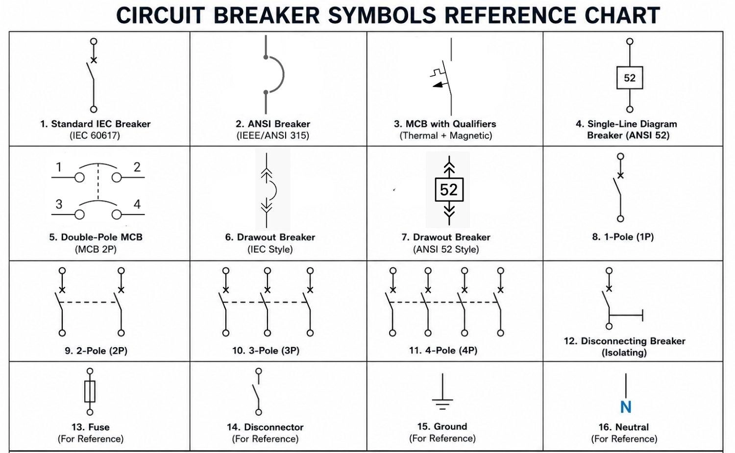
IEC Circuit Breaker Symbol
- Standard IEC Switch with Cross: Angled switch contact with a cross or asterisk qualifier. Standard European schematic symbol.
- Disconnecting Breaker: Angled contact with a cross/asterisk qualifier and a terminal perpendicular bar.
ANSI Circuit Breaker Symbol
- ANSI Box Symbol: Inline square box on a line. Standard North American single-line symbol.
- ANSI Contact Gap: Standard switch contact gap with a small curved graphical element.
Circuit Breaker Pole Configuration Symbols
- 1P / 2P / 3P / 4P: Single, double, triple, and quad parallel contacts connected by a mechanical dashed line.
- 1P+N / 3P+N: Linked multi-pole contacts where the neutral contact ("N") is a plain switch without any overcurrent sensors.
MCB Symbols
- Thermal-Magnetic MCB: Angled switch contact combined with bimetal steps and loop coils.
- Thermal-magnetic MCBs: Thermal-magnetic MCBs may be shown with additional overload and magnetic-trip qualifiers depending on the drafting system used.
IEC vs ANSI Circuit Breaker Symbol
Standards split how these functions are visualized.
IEC 60617 symbols are typically derived from switch-contact symbols with additional breaker qualifiers depending on the symbol library and protection type.
ANSI/IEEE 315 diagrams may use contact-based breaker symbols in detailed schematics and simplified breaker symbols in single-line diagrams.
| Attribute | IEC 60617 Standard | ANSI/IEEE 315 Standard |
|---|---|---|
| Primary Reference | IEC 60617 database | IEEE 315-1975 |
| Elementary Schematics | Contact-based switch symbols with protective qualifiers | Contact-based symbols or traditional gap lines |
| Single-Line Diagrams | Simplified contact with qualifier or straight line | Inline square box |
| AC Breaker Identifier | Reference designator Q or QF | Device Number 52 |
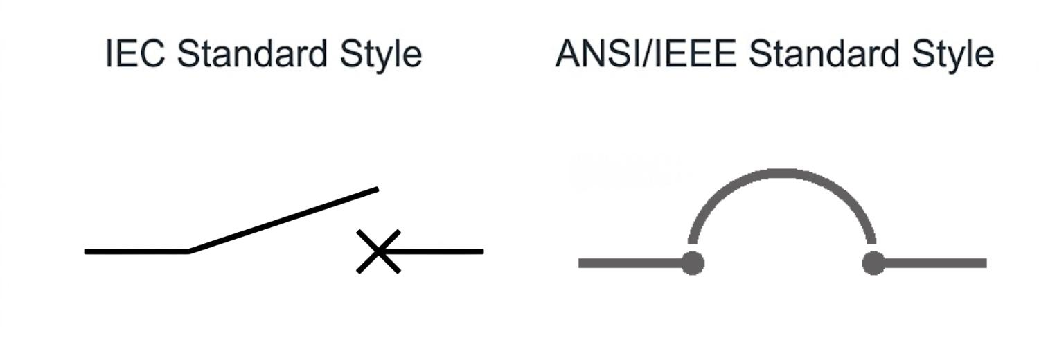
Figure: Comparison showing the IEC switch-contact-based circuit breaker symbol with a cross qualifier, and the ANSI/IEEE contact gap style symbol with a curved arc.

Once your layout is finalized, upload your files to get an instant online quote and transition smoothly from prototypes to production with JLCPCB's PCB Assembly services.
Common IEC Circuit Breaker Symbols
The international drafting standard relies on modular graphics that build on basic switch contacts.
Standard IEC Circuit Breaker Symbol
In standard European schematics, the basic circuit breaker is drawn as an angled contact arm with a cross or asterisk qualifier placed on the contact path. This indicates a resettable, fault-capable device.
IEC Circuit Breaker Function Representation
When a drawing focuses strictly on control logic rather than individual phase poles, a standalone cross qualifier is used to represent the circuit breaker function block on control schematics.
IEC Circuit Breaker with Disconnector Function
For safety isolation, a disconnecting breaker must show both the fault interruption capability and a verified physical isolation gap. This is represented by adding a perpendicular bar to the end of the contact arm, indicating an integrated disconnector function.
IEC Withdrawable Circuit Breaker Symbol
To show a withdrawable circuit breaker that can be isolated from live busbars for servicing, standard drafting adds double chevrons pointing inward and outward on the incoming and outgoing terminal lines.
ANSI Circuit Breaker Symbol
North American drawings use dedicated graphic conventions that simplify multi-phase lines on large single-line diagrams.
ANSI Contact-Gap Circuit Breaker Symbol
On detailed elementary schematics, the ANSI breaker is shown as a switch contact gap, often accompanied by a small curved graphical element representing arc-suppression capabilities.
ANSI Single-Line Circuit Breaker Symbol
To reduce clutter on high-voltage and industrial distribution plans, ANSI single-line diagrams represent the breaker as a simple, clean square box placed directly on the phase line.
ANSI Device Number 52 for AC Circuit Breakers
ANSI device number 52 is commonly used to identify AC circuit breakers on single-line diagrams. On protection schematics, the inline square box is typically labeled with "52" inside or directly adjacent to the box.
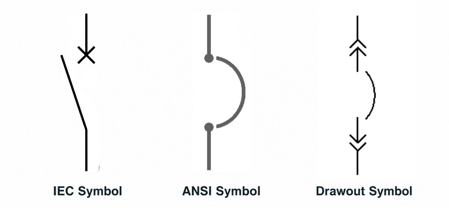
Figure: Showing standard IEC, ANSI, and Drawout circuit breaker symbols.
MCB Symbol (Miniature Circuit Breaker Symbol)
Miniature Circuit Breakers protect branch distribution lines. Many real drawings simply identify the device as an MCB by tag, designation, or schematic context, rather than relying on a single mandatory symbol.
Single-Pole MCB Symbol
This represents a basic single-phase MCB. It is typically drawn as an angled contact, but the exact representation depends on whether the manufacturer's drawing uses a simplified arc representation or detailed bimetallic indicators.
Double-Pole MCB Symbol
Double-pole MCBs are represented in commercial catalogs with a dual contact configuration. Following standard manufacturer drawings, each pole is drawn as an upward-curving arc path bridging terminal circles. The two paths are connected in parallel by a dashed line representing the mechanical trip linkage, with active lines wired in parallel: top input terminals labeled 1 and 3 on the left, and bottom output terminals labeled 2 and 4 on the right.
Three-Pole MCB Symbol
Used for three-phase low-voltage loads, this shows three parallel breaker poles. On single-line diagrams, it is often simplified to a single contact with three slash marks.
Four-Pole MCB Symbol
A four-pole MCB is utilized in systems requiring neutral interruption along with three-phase protection. The schematic layout details four adjacent contacts connected by the standard mechanical dashed line.
Thermal-Magnetic MCB Symbol
Thermal-magnetic MCBs may be shown with additional overload and magnetic-trip qualifiers depending on the drafting system used. When represented in full detail, the symbol features a stepped, bimetallic square wave to show thermal protection and a loop coil to show instantaneous magnetic protection.
MCB Symbols in Single-Line Diagrams
On highly compressed single-line diagrams, MCBs are represented using a simplified, space-saving format. Instead of drawing complex contact paths for every phase, a single line is shown with a standard single-line breaker symbol. The phase count is then indicated by drawing simple diagonal slashes across the conductor lines.
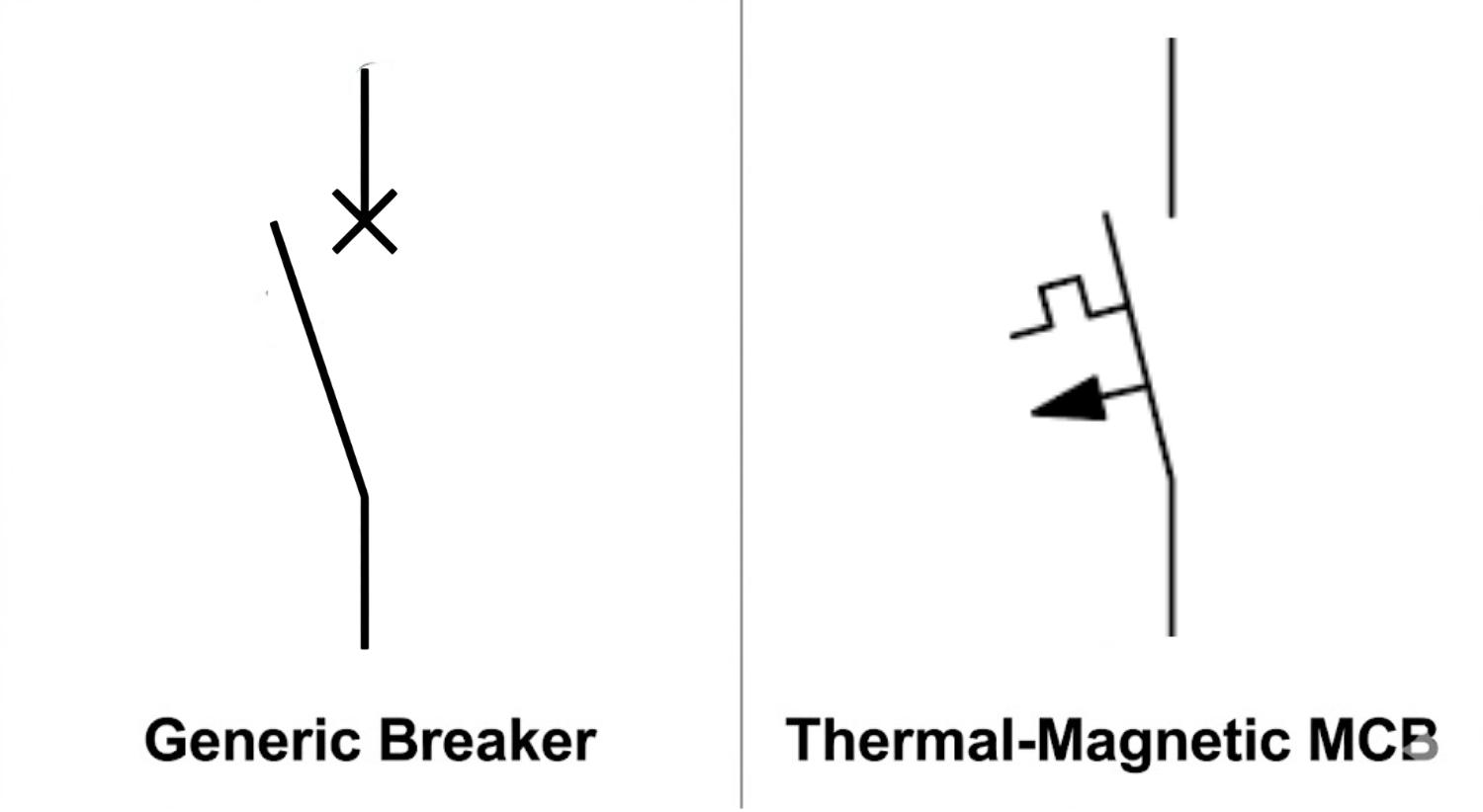
Figure: Comparison showing a generic breaker contact symbol and a detailed thermal-magnetic MCB symbol.
Circuit Breaker Pole Configuration Symbols
The pole count of a circuit breaker indicates how many separate current paths the device can open or close simultaneously.
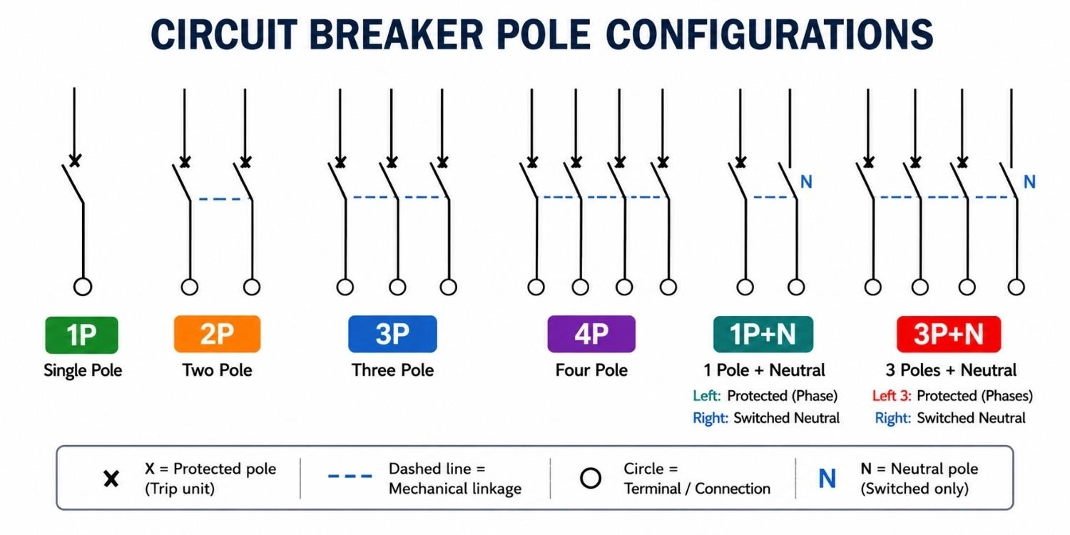
Figure: Comparing 1P, 2P, 3P, 4P, 1P+N, and 3P+N circuit breaker symbols with dashed mechanical operating linkages.
1P Circuit Breaker Symbol
A single-pole breaker symbol shows a single contact path. It is used to protect and switch a single live hot conductor in single-phase circuits.
2P Circuit Breaker Symbol
A 2-Pole breaker symbol shows two identical, parallel contact paths. A dashed horizontal or vertical line connects both contact arms, representing a shared mechanical trip mechanism. If a fault occurs on either phase, both lines are disconnected simultaneously.
3P Circuit Breaker Symbol
A 3-Pole circuit breaker symbol shows three parallel, identical contact paths linked together by a dashed mechanical line. This configuration is standard for protecting three-phase electrical loads, such as motors and industrial machinery.
4P Circuit Breaker Symbol
A 4-Pole breaker switches four conductors simultaneously. Protection arrangements vary by manufacturer and breaker design. Unlike a simple switched neutral, a dedicated four-pole breaker may contain overcurrent protection on all four lines depending on application requirements.
1P+N Circuit Breaker Symbol
In many 1P+N designs, the phase pole contains overcurrent protection while the neutral pole is switched only. The neutral contact is mechanically linked to the phase contact but does not feature independent overcurrent trip sensors.
3P+N Circuit Breaker Symbol
Many 3P+N breakers use protected phase poles with a switched neutral pole. Only the three active phases are monitored for overcurrent faults, while the neutral pole is opened mechanically alongside the phases for complete isolation.
Thermal-Magnetic Circuit Breaker Symbols
To show exactly what protective technologies are built into a circuit breaker, designers add standard graphical elements adjacent to or inline with the breaker contacts.
Thermal Circuit Breaker Symbol
The thermal-overload function protects against slow, continuous overcurrents. It is represented by a stepped, bimetallic square wave profile placed directly inline with the breaker contact.
Magnetic Circuit Breaker Symbol
The magnetic-trip function protects against rapid, extreme short-circuit currents. It is represented by a small circular loop or coil symbol placed adjacent to the breaker contact.
Thermal-Magnetic Circuit Breaker Symbol
The standard thermal-magnetic breaker symbol combines both functions. It displays the stepped bimetallic profile and the magnetic loop coil inline on the same contact path. This indicates dual-action protection against both sustained overloads and instant short circuits.
Overcurrent Protection Elements in IEC Symbols
In IEC schematics, overcurrent indicators are modular. A single-phase contact might be accompanied by only a thermal step, only a magnetic coil, or both, allowing engineers to verify that the protection matches the specific motor or transformer load requirements.
How to Read Circuit Breaker Symbols on Single-Line Diagrams
Reading industrial drawings accurately requires a systematic approach to identifying the device's characteristics from its symbol.
Step 1: Identifying Pole Count
Count the individual contact lines that are aligned side-by-side. If they are connected by a dashed linkage line, they represent a multi-pole breaker. For single-line diagrams, count the number of diagonal slashes crossing the wire path to determine the pole count.
Step 2: Identifying Mechanical Linkage
Look for a dashed line connecting the contacts. This mechanical linkage indicates that all poles are physically linked. If any single pole trips due to a fault, the mechanism will force all other poles to open at the exact same time, preventing dangerous single-phasing conditions on three-phase motors.
Step 3: Identifying Drawout Breakers
Look for double chevrons (<< and >>) flanking the breaker symbol. These racking arrows indicate a drawout type breaker mounted in industrial drawout switchgear, allowing safe mechanical isolation for maintenance.
Step 4: Identifying ANSI Device Number 52
On North American drawings, look for the device number 52 written inside or adjacent to the square box on single-line paths. This identifies an AC power circuit breaker rather than a manual switch or load-break switch.
FAQs About Circuit Breaker Symbols
Q: What Is the Standard Circuit Breaker Symbol?
The standard symbol depends on the drawing's standard. IEC drawings typically use switch-contact based circuit breaker symbols with additional qualifiers depending on the symbol set being used. ANSI drawings may use contact-based breaker symbols or simplified single-line breaker symbols, often associated with device number 52.
Q: What Does a 2-Pole Breaker Symbol Mean?
A 2-pole breaker symbol shows two identical, parallel contact paths linked together by a dashed line. This dashed line represents a shared mechanical mechanism, indicating that both poles trip simultaneously if an overcurrent or short-circuit fault occurs on either line.
Q: What Is the Difference Between 2P and 1P+N Symbols?
A 2P symbol displays two parallel contacts with active overcurrent protection (thermal/magnetic sensors) on both paths. A 1P+N symbol shows two linked contacts where only the phase pole is monitored for overcurrent, while the neutral contact (labeled "N") acts as a switched-only path with no trip sensors.
Q: How Do You Identify a 3-Phase Circuit Breaker Symbol?
A 3-phase circuit breaker symbol is identified by three parallel switch contacts aligned side-by-side, connected by a dashed mechanical linkage line. Alternatively, in simplified block diagrams, it is represented by three diagonal slashes drawn across its terminal lines.
Q: What Is ANSI Device Number 52?
ANSI device number 52 is the standard code for an AC power circuit breaker, as defined in the IEEE Std C37.2-2022 system. Using standardized numbers like 52 on protection drawings helps engineers quickly identify the device's function without relying solely on graphic symbols.
Q: What Does the Dashed Line Between Breaker Poles Mean?
The dashed line represents a physical, mechanical linkage connecting the operating mechanisms of each pole. This ensures that if any single pole trips due to a fault, the mechanism will force all other poles to open at the exact same time, preventing dangerous single-phasing conditions on three-phase motors.
Q: What is the Difference Between a Circuit Breaker Symbol and a Switch Symbol?
The primary difference lies in fault interruption capability. A basic switch symbol represents a manually operated contact with no automatic trip capabilities. A circuit breaker symbol includes structural indicators, such as a cross or an arc gap, signifying that the device can automatically break current in response to electrical faults.
Conclusion
Reading and drafting circuit breaker symbols accurately is a core skill for electrical engineering. By understanding the visual logic behind these symbols, you can easily read schematic diagrams across different standards and industries:
- Key Symbol Categories: Real-world symbols range from commercial semicircle arcs to standardized IEC contact lines and ANSI boxes.
- IEC and ANSI Considerations: Always check the standard framework of your drawing. Look for the IEC switch contact qualifiers, or the ANSI square box with device code 52.
- Pole Configuration Identification: Use linked contacts with dashed lines or diagonal slashes to determine the pole count. Pay close attention to specialized neutral switching like 1P+N or 3P+N, where the neutral line is switched but not monitored for faults.
- Protection-Function Identification: Identify built-in protection technologies by looking for inline thermal bimetallic steps, magnetic loops, and differential current sensors.
Popular Articles
• How to Identify SMD LED Polarity: Markings, Testing, and PCB Tips
• How to Create a Bluetooth-Controlled Car With Arduino: A Step-by-Step Guide
• How to Design and Assemble a Reliable ESP32 Module PCB on a 2-Layer Board
• The Ultimate Guide to Relay Symbol: Coil, Contacts, Diagrams, and Circuit Applications
• The Ultimate Guide to PCBA: Process,Types and Techniques for the Electronics Enthusiast
Keep Learning
How to Design an ESP32-S3 Development Board from Scratch: A 4-Layer PCB Design Tutorial
Designing your own ESP32-S3 development board gives you complete control over your hardware architecture while preparing your IoT projects for commercial production. Instead of relying on bulkier, off-the-shelf boards, building a custom design allows you to optimize the board space, expose only the required GPIO pins, and integrate peripherals directly onto a single substrate. In this tutorial, we will design a 4-layer ESP32-S3 development board from scratch. We will walk through the entire hardware d......
Circuit Breaker Symbols Explained: IEC, ANSI, MCB, and Pole Configuration Symbols
Electrical schematics are the universal language of power systems, control circuits, and printed circuit boards. Within these diagrams, the circuit breaker symbol is one of the most critical elements. Getting it right is essential for safety, troubleshooting, and manufacturing. An error as simple as mixing up a circuit breaker with a manual switch or an isolator can lead to catastrophic misinterpretations on the factory floor or during field maintenance. This guide provides a complete, technically acc......
How to Identify SMD LED Polarity: Markings, Testing, and PCB Tips
Surface-mount LED components are ubiquitous in electronics design, serving as everything from simple power indicators to complex lighting arrays. Unlike standard resistors, LEDs are polarized diodes. Identifying SMD LED polarity correctly is critical for prototype troubleshooting and high-volume PCB assembly. A reversed LED results in no light output, broken circuit paths, and potential diode breakdown if the reverse voltage exceeds the component's maximum rating (typically 5V or less for most indicat......
Arduino LED Driver Tutorial: Control More LEDs with 74HC595 and MAX7219
Arduino GPIO pins run out quickly in larger LED projects. By utilizing dedicated LED drivers and expansion ICs, you can drastically reduce pin usage, eliminate processor-heavy multiplexing loops, and simplify display wiring. In this guide, you will learn the operational architecture, wiring configurations, cascading techniques, and optimization strategies for the 74HC595 shift register and the MAX7219 LED driver. Why Arduino Projects Need LED Driver ICs Arduino GPIO and Current Limitations An ATmega32......
How to Create a Bluetooth-Controlled Car With Arduino: A Step-by-Step Guide
This tutorial walks through the complete engineering and implementation of a two-wheel Bluetooth RC car with an Arduino Nano module on a specially designed PCBA (Printed Circuit Board Assembly). While many hobbyists start by wiring motors and Bluetooth modules with jumper cables on a breadboard, this approach is prone to disconnection and signal noise. This guide upgrades that process by teaching you how to design a professional mainboard. Key Design Features Controller: Arduino Nano used as a plug-in......
Fiducial Marks in PCB and SMT Assembly: A Complete Guide to Accuracy and Design Rules
Modern Printed Circuit Boards (PCBs) are complex, integrating high-density components like 0.4mm pitch Ball Grid Arrays (BGAs), 0201 passives, and fine-pitch Quad Flat No-Lead (QFN) packages. In this advanced manufacturing environment, achieving placement accuracy measured in micrometers is crucial. A significant challenge in automated manufacturing is how pick-and-place machines, which handle thousands of components per hour, precisely locate the PCB. A board on a conveyor system is never in the perf......