
Arduino LED Driver Tutorial: Control More LEDs with 74HC595 and MAX7219
18 min
- Why Arduino Projects Need LED Driver ICs
- Arduino LED Driver IC Comparison
- How to Use 74HC595 with Arduino for LEDs and LED Matrices
- How to Use a MAX7219 LED Matrix Module with Arduino
- Power Requirements for Arduino LED Matrix Displays
- Arduino LED Driver Troubleshooting
- Arduino LED Driver Projects
- Conclusion
- FAQs about Arduino LED Driver
Arduino GPIO pins run out quickly in larger LED projects. By utilizing dedicated LED drivers and expansion ICs, you can drastically reduce pin usage, eliminate processor-heavy multiplexing loops, and simplify display wiring.
In this guide, you will learn the operational architecture, wiring configurations, cascading techniques, and optimization strategies for the 74HC595 shift register and the MAX7219 LED driver.
Why Arduino Projects Need LED Driver ICs
Arduino GPIO and Current Limitations
An ATmega328P-based Arduino Uno has physical limits that make large-scale LED direct-driving impossible:
- Maximum Current per Pin: A single digital I/O pin can safely source or sink a maximum of 20 mA continuously (absolute peak limit is 40 mA).
- Total Package Limit: The combined current flowing through the main VCC and GND pins of the microcontroller must not exceed 200 mA.
- Physical Pin Shortage: The Arduino Uno offers only 14 digital I/O pins and 6 analog input pins.
If you attempt to drive sixteen standard 15 mA LEDs simultaneously, you will demand 240 mA from the microcontroller package - violating the safe operating envelope and risking instant thermal destruction of the silicon.
LED Multiplexing vs. LED Driver ICs
When driving standard arrays (such as 8x8 matrices or 7-segment displays), you face a choice between direct software-driven multiplexing and dedicated hardware driver ICs:
- Direct GPIO Multiplexing: Requires the Arduino CPU to run a high-frequency loop to scan rows and columns continuously. If the main loop gets blocked by a sensor read, serial communication, or a delay() call, the display will instantly freeze or flicker.
- Shift Registers (74HC595): Expand digital output pins using a simple 3-pin serial interface. While they solve physical pin limits cheaply, the microcontroller must still execute the high-speed scanning loop in software to multiplex matrices.
- Dedicated Display Drivers (MAX7219): Completely offload multiplexing from the CPU. They contain built-in static RAM to hold display data and hardware oscillators to handle row/column sweeps automatically, freeing up the Arduino CPU entirely.
74HC595 vs. MAX7219: Which LED Driver Should You Choose?
- Choose the 74HC595 if you need general-purpose digital output expansion (e.g., controlling a bank of relays, custom bar graphs, or individual status indicators) at a very low component cost.
- Choose the MAX7219 if your project specifically involves 8x8 LED grids, scrolling text banners, or multi-digit 7-segment readouts, as it handles current limiting, scanning, and dimming on a single silicon die.
Arduino LED Driver IC Comparison
The tables below outline the core differences between standard output expanders and dedicated display controllers.
| Feature | 74HC595 Shift Register | MAX7219 LED Driver |
|---|---|---|
| Silicon Role | 8-Bit Serial-to-Parallel Expander | Integrated Common-Cathode Driver |
| Required Control Pins | 3 Pins (Data, Clock, Latch) | 3 Pins (SPI: DIN, CS, CLK) |
| Max LED Capacity | 8 individual LEDs per chip | 64 matrix LEDs or 8 display digits |
| Multiplexing Duty Cycle | Managed in software by the CPU | Automatically swept at 800Hz in hardware |
| Onboard Display RAM | None (Latched output registers only) | 8x8 Dual-Port Static RAM |
| Current Limiting | Requires 8 external resistors per chip | Set using one single external resistor (R_iset) |
| Brightness Control | Manual PWM on Output Enable (OE) pin | Built-in 16-level digital register control |
| Cascading Capacity | Infinite (Limited by signal propagation) | Up to 8+ modules cleanly (Limited by SPI speed) |
How to Use 74HC595 with Arduino for LEDs and LED Matrices
The 74HC595 shift register is a highly cost-effective chip to expand your output pins.
74HC595 Pinout Explained
The 74HC595 contains an 8-bit shift register and an 8-bit D-type storage register. Key pins include:
- DS (Pin 14): Serial Data Input.
- SH_CP (Pin 11): Shift Register Clock. Active on the rising edge.
- ST_CP (Pin 12): Storage Register Clock (Latch). Updates parallel output pins.
- OE (Pin 13): Output Enable. Active LOW.
- MR (Pin 10): Master Reset. Active LOW.
- Q0 - Q7 (Pins 15, 1-7): Parallel outputs.
- Q7' (Pin 9): Serial Out (for daisy-chaining).
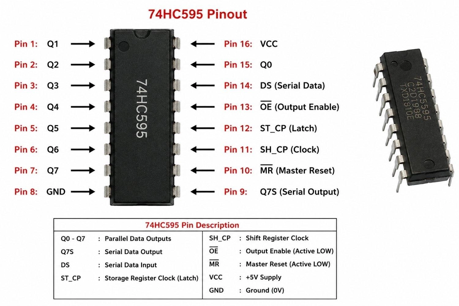
Figure: Pinout diagram of a 74HC595 8-bit shift register IC in a DIP-16 package.
74HC595 Arduino 8x8 LED Matrix Wiring Diagram
To hook up a dual shift register configuration for an 8x8 LED matrix, connect the clock and latch pins of both registers in parallel to the Arduino, and daisy-chain their serial data lines.
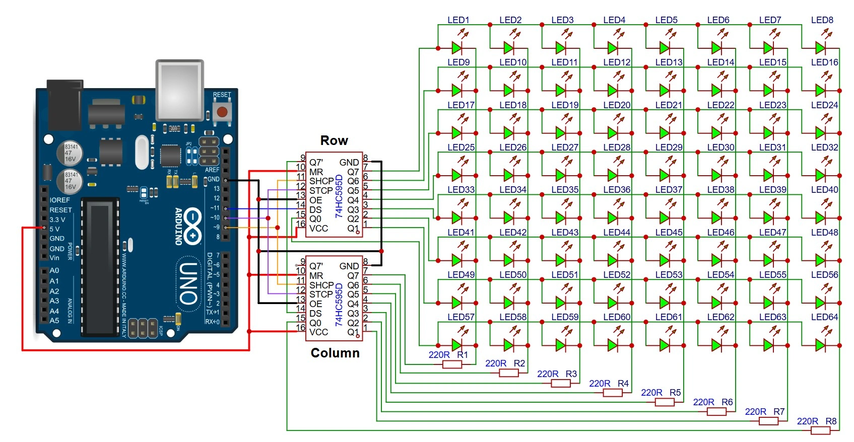
Figure: Detailed wiring schematic showing an Arduino Uno controlling two daisy-chained 74HC595 shift registers. The first register controls row anodes; the second register controls column cathodes with series resistors, sharing latch and clock signals.
Arduino 74HC595 LED Matrix Code with shiftOut()
This code demonstrates how to scan a 3D-buffered image (such as a heart pattern) on an 8x8 LED matrix using a dual-register daisy-chain. By shifting out two bytes sequentially, the columns and rows are updated on each scan line.
Code Highlights:
- Cascading Shift Operation: Holds the latch LOW while shifting out two 8-bit values back-to-back. The first byte overflows into Register 2 (Columns) while the second byte populates Register 1 (Rows).
- Column and Row Polarity Mapping: Inverts column values (~pattern) to drive cathodes LOW, and sets individual row pins HIGH via a bitwise shift.
- Stable Refresh Interleaving: Employs a low-delay loop to step through each scan line sequentially, providing a steady, flicker-free visual image.
const int latchPin = 10;
const int clockPin = 9;
const int dataPin = 11;

// 8x8 heart pattern representation (1 = active LED, 0 = off LED)
byte heartPattern[8] = {
  B00000000,
  B01100110,
  B11111111,
  B11111111,
  B11111111,
  B01111110,
  B00111100,
  B00000000
};// Setup
void setup() {
pinMode(latchPin, OUTPUT);
pinMode(clockPin, OUTPUT);
pinMode(dataPin, OUTPUT);
}// Main Loop
void loop() {
// Scan through all 8 rows sequentially
for (int row = 0; row < 8; row++) {
// Columns (active LOW): Invert the pattern so that 1s are driven LOW (sinking current)
byte colData = ~heartPattern[row];
// Rows (active HIGH): Turn on only the current row (e.g. Row 0 -> B00000001, Row 1 -> B00000010)
byte rowData = (1 << row);
// Ground the latch pin and hold it LOW as long as we are transmitting data
digitalWrite(latchPin, LOW);
// 1. Shift out column data first (this byte overflows into Register 2, controlling Columns)
shiftOut(dataPin, clockPin, MSBFIRST, colData);
// 2. Shift out row data second (this byte stays in Register 1, controlling Rows)
shiftOut(dataPin, clockPin, MSBFIRST, rowData);
// Return the latch pin HIGH to output the updated states simultaneously
digitalWrite(latchPin, HIGH);
// Delay interval per scan line (1.25 ms per row achieves ~100 Hz frame refresh rate)
delayMicroseconds(1250);
}
}While software-based shiftOut() is simple and convenient, it relies on manual software toggling of the clock and data pins, which introduces execution overhead. For highly demanding, high-frequency displays, you can switch to the Arduino's hardware SPI (Serial Peripheral Interface) bus. Hardware SPI utilizes the ATmega328P's dedicated internal shift register circuitry, freeing up CPU clock cycles and allowing data transfer rates up to 8 MHz.
Daisy-Chaining Multiple 74HC595 Shift Registers
To control more than 8 outputs, you can chain multiple shift registers together without using more pins on the Arduino. Connect the serial output Q7' (Pin 9) of the first register to the serial data input DS (Pin 14) of the second register. Connect the clock (SH_CP) and latch (ST_CP) pins of both chips in parallel to the same Arduino control lines.
Because of the FIFO (First-In, First-Out) nature of serial shifting, sending 16 bits of data means the first 8 bits shifted will overflow out of the first chip and settle into the second chip. Therefore, when using MSBFIRST transmission, the data byte intended for the second shift register in the chain must be shifted out first.
74HC595 PWM Brightness Control Using the OE Pin
To implement global brightness control, connect the OE (Output Enable) pin of the 74HC595 to one of the Arduino’s PWM-enabled pins (like D3 or D9) instead of hardwiring it to ground. By writing an analog value using analogWrite(OEPin, brightnessValue) (where 0 is fully bright and 255 is off), you can modulate the output enable time of the registers.
How to Use a MAX7219 LED Matrix Module with Arduino
While wiring bare integrated circuits (ICs) on breadboards is useful for foundational learning, practical makers and product developers almost exclusively use widely available MAX7219 8x8 LED matrix modules. These inexpensive, off-the-shelf breakout boards come with a surface-mount MAX7219 IC, decoupling capacitors, and the matrix socket already soldered onto a compact PCB, making hardware integration plug-and-play.
MAX7219 8x8 LED Matrix Working Principle
A MAX7219 8x8 LED matrix module handles the multiplexing refresh completely "on-board." The module contains an internal 8x8 dual-port static RAM.
When your Arduino transmits pixel data to the board over its high-speed SPI bus, those states are written directly to this onboard memory. The driver then automatically and continuously scans through the grid at a fixed internal rate of 800 Hz.
Because the module updates the hardware internally, your Arduino is entirely relieved from the CPU-heavy Persistence of Vision (PoV) loop, preventing screen flicker when your main loop performs slower tasks.
MAX7219 8x8 LED Matrix Pinout & Interconnection
Standard MAX7219 8x8 LED matrix modules typically break out all required SPI lines onto simple, user-friendly 5-pin headers at opposite ends of the PCB (commonly designated as "Input" and "Output" sides).
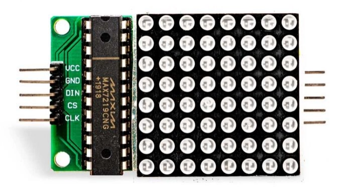
Figure: MAX7219 8x8 LED matrix module showing the standard 5-pin input header(Left) for Arduino communication and the 5-pin output header(Right) for daisy-chaining.
- VCC: Power input (typically +5V DC).
- GND: System ground reference.
- DIN (Data In): Serial data input connected to the microcontroller's MOSI line.
- CS (Chip Select / LOAD): Pin triggered LOW to begin transmission, and HIGH to latch incoming bytes.
- CLK (Serial Clock): Synchronizes byte transmission up to 10 MHz.
- DOUT (Data Out): Found on the output header. Used to chain multiple modules together.
Integrated R_iset Resistor placement
On a raw silicon chip, the peak LED segment current must be adjusted using a calculated external resistor (R_iset) connected to the ISET pin.
On standard MAX7219 8x8 LED matrix modules, this current-setting resistor is already integrated onto the board (usually a surface-mount 10k ohms resistor). This preset resistor configures the peak segment current safely to 40 mA for standard red LEDs, completely eliminating the need for you to calculate, breadboard, or solder discrete resistors yourself.
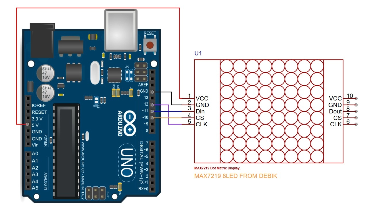
Figure: Schematic diagram showing the wiring connections between an Arduino Uno and a MAX7219 8x8 LED matrix module.
MAX7219 Control Registers
At a low level, communication with the module is accomplished by transmitting a 16-bit packet composed of an 8-bit Address Register, followed by an 8-bit Data Byte:
Command Byte = [Address (D15-D8)] + [Data Byte (D7-D0)]
The primary control registers internally mapped on the board are:
| Register Address (Hex) | Register Name | Purpose / Common Settings |
|---|---|---|
| 0x09 | Decode Mode | 0x00 for 8x8 matrix raw column mapping; 0x0F/0xFF for 7-segments. |
| 0x0A | Intensity | Internal digital dimming from 0x00 (min) to 0x0F (max, 15/16 duty cycle). |
| 0x0B | Scan Limit | Set to 0x07 to tell the driver to sweep all 8 rows/columns. |
| 0x0C | Shutdown | 0x00 for low-power standby; 0x01 for active run mode. |
| 0x0F | Display Test | 0x00 for normal operation; 0x01 to override and illuminate all LEDs. |
| 0x01 to 0x08 | Digit 0 to 7 | Maps directly to Columns 1 to 8 on your 8x8 LED matrix module. |
Dedicated Arduino Libraries vs. Low-Level Control
While sending raw register codes using the hardware SPI.h library is highly educational for understanding under-the-hood registers, writing complex graphics or scrolling text from scratch is tedious.
For actual projects, developers leverage dedicated, highly optimized open-source libraries that make controlling MAX7219 LED matrix modules incredibly easy:
-
LedControl (Arduino Official Library): A lightweight, beginner-friendly library that allows you to address individual modules or small chains, toggle individual LEDs with coordinates (setLed()), or display characters.
-
MD_MAX72XX and MD_Parola: The gold standard for commercial and hobbyist projects. It handles hardware configuration variations (like FC-16 module layouts), multi-digit scrolling text buffers, fonts, entry/exit text animation effects, and multi-line zone layouts with minimal coding overhead.
Example: Conceptual Low-Level SPI Control
The code below demonstrates how a dedicated library interacts with the MAX7219’s internal registers under the hood using Arduino's native hardware SPI.h bus.
// Pin Definitions
// Includes and Definitions
#include <SPI.h>
const int csPin = 10;

// MAX7219 Register Addresses
const byte REG_NOOP         = 0x00;
const byte REG_DIGIT0       = 0x01;
const byte REG_DECODE_MODE  = 0x09;
const byte REG_INTENSITY    = 0x0A;
const byte REG_SCAN_LIMIT   = 0x0B;
const byte REG_SHUTDOWN     = 0x0C;
const byte REG_DISPLAY_TEST = 0x0F;


// Display Pattern Buffer
byte heartPattern[8] = {
  B00000000,
  B01100110,
  B11111111,
  B11111111,
  B11111111,
  B01111110,
  B00111100,
  B00000000
};// Helper Function to Write to Register
void writeRegister(byte address, byte data) {
digitalWrite(csPin, LOW);
SPI.transfer(address);
SPI.transfer(data);
digitalWrite(csPin, HIGH);
}// Setup Function
void setup() {
pinMode(csPin, OUTPUT);
digitalWrite(csPin, HIGH);
SPI.begin();
SPI.beginTransaction(SPISettings(8000000, MSBFIRST, SPI_MODE0));
writeRegister(REG_DISPLAY_TEST, 0x00);
writeRegister(REG_DECODE_MODE, 0x00);
writeRegister(REG_INTENSITY, 0x03);
writeRegister(REG_SCAN_LIMIT, 0x07);
writeRegister(REG_SHUTDOWN, 0x01);
for (int i = 1; i <= 8; i++) {
writeRegister(i, 0x00);
}
}// Main Loop
void loop() {
for (int col = 0; col < 8; col++) {
writeRegister(REG_DIGIT0 + col, heartPattern[col]);
}
delay(1000);
}Daisy-Chaining MAX7219 8x8 LED Matrix Modules
Cascading multiple MAX7219 8x8 LED matrix modules to build a wide banner display is remarkably straightforward.
You simply mount the modules side-by-side. Connect the common lines - VCC, GND, CLK, and CS - in parallel across all boards (usually easily done using standard female-to-female DuPont jumper cables).
For the serial data path, route the DOUT (Data Out) pin on the right-hand output header of the first module directly into the DIN (Data In) pin on the left-hand input header of the adjacent module.
When you use higher-level libraries like MD_Parola, you simply declare the total number of connected modules in your setup configurations (e.g., #define MAX_DEVICES 4). The library automatically coordinates shifting the serial text buffers through the chained boards, creating seamless, synchronized multi-module text scrolls.
Power Requirements for Arduino LED Matrix Displays
While a single module can run safely off your Arduino's 5V onboard regulator, larger cascaded arrays will quickly blow past the USB power budget:
- USB 2.0 Supply Limit: Standard computer USB ports cap supply currents at 500mA.
- Cascaded current consumption: An 8x32 (4-module) display running at full brightness can easily pull 600 mA to 1A under high pixel density.
- The solution: Connect an external, regulated 5V power supply rated for at least 2A directly to the VCC and GND rails of your LED modules. Crucially, always connect the GND line of the external power supply to the Arduino's GND pin to maintain a common ground reference.
Arduino LED Driver Troubleshooting
#1 74HC595 Outputs Not Updating
If your LEDs are not changing state, check the Latch (ST_CP) wire. If this line is disconnected or shorted to GND, the shift register will receive the data, but it will never load the values onto the physical output pins.
#2 Incorrect LED Order After Cascading
If your LEDs are lighting up in reverse order or shifting data into the wrong register, you have a FIFO mapping error. Remember that the data byte shifted out first gets pushed into the second chip in the chain. Try swapping the order of your shiftOut() calls in your code.
#3 MAX7219 Matrix Not Displaying Text
If a cascaded matrix remains completely blank, the most common culprit is a missing wake-up sequence. The MAX7219 boots up in a default low-power Shutdown state.
Your setup code must explicitly write 0x01 to the Shutdown register (0x0C) and configure the Scan Limit register (0x0B) to 0x07 to enable all 8 rows.
#4 LED Matrix Is Dim or Uneven
If the LEDs look dim or fade as you go down a cascaded chain, check your power distribution. The trace resistance of thin jumper wires causes a voltage drop.
Always route heavy-gauge wire directly from your 5V power supply to each module's power input pin rather than daisy-chaining the thin VCC wires from board to board.
#5 LED Display Flickers
Flickering is almost always caused by a missing ground reference. If your modules are powered by an external adapter and you forgot to run a wire between the adapter's negative terminal and the Arduino's GND pin, the high-speed SPI signals will fluctuate wildly relative to the floating reference.
#6 Startup State Problems
During power-on, the shift register outputs can float or initialize randomly, causing a brief, unwanted flash of all connected LEDs.
To prevent this, place a 10k Ohm pull-up resistor from the OE pin to VCC. This forces the outputs into a high-impedance (disabled) state at startup. Once the Arduino boot sequence is complete, your setup code can write the OE pin LOW to enable clean output states.
Arduino LED Driver Projects
8x32 MAX7219 Scrolling Text Display
By cascading four standard 8x8 modules and utilizing the MD_Parola library, you can build a large scrolling billboard display with fluid entry and exit text animations.
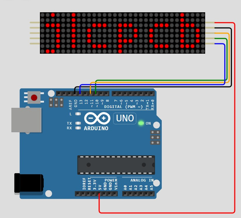
Figure: Four 8x8 LED matrix modules attached by daisy chain for a text display project with Arduino
Large LED Bar Graph Using 74HC595
By chaining three 74HC595 shift registers together, you can drive a highly sensitive 24-segment audio level indicator or battery gauge with exceptional brightness and zero pin overhead.
Arduino 7-Segment Display Multiplexing
For projects requiring numeric readouts, an Arduino 7-segment display multiplexing setup is a classic implementation. A typical multi-digit 7-segment display relies on a standard arrangement of seven individual segment LEDs labeled a, b, c, d, e, f, and g, along with an optional eighth decimal point segment (dp).
In a 4-digit package, this translates to 12 total physical interface pins: 8 pins linked in parallel to map the segments of all digits, and 4 common cathode or common anode pins to select which digit is active.
Many Arduino 7-segment multiplexing projects use 74HC595 shift registers or MAX7219 drivers to reduce GPIO usage and simplify refresh timing. This setup is highly versatile, whether you are using common-anode or common-cathode configurations.
Instead of using 32 pins to drive four digits directly, multiplexing cycles through the four common pins sequentially while shifting the appropriate segment data. When scanned rapidly, the individual digits merge to form a continuous multi-digit display without visible flickering.

- If you are moving from breadboard prototypes to a custom LED display PCB, plan the current paths, connector placement, decoupling capacitors, and driver IC footprints early.
- JLCPCB PCB fabrication and assembly services can help turn Arduino LED driver prototypes into compact production-ready boards.
Conclusion
Arduino LED Drivers allow small microcontrollers to control surprisingly large displays using careful scan timing and shared wiring architectures. Matrix scanning, 74HC595 shift registers, Charlieplexing, and MAX7219 drivers each solve different scaling problems depending on GPIO limits, brightness requirements, CPU overhead, and circuit complexity.
FAQs about Arduino LED Driver
Q: How Many LEDs Can One 74HC595 Control?
A single 74HC595 shift register has 8 parallel outputs, allowing it to control up to 8 individual LEDs directly. However, you can daisy-chain multiple registers in series to scale up outputs indefinitely.
Q: How Many MAX7219 Modules Can Be Cascaded?
You can cleanly cascade up to 8 MAX7219 modules in series over a standard hardware SPI bus before signal propagation delays on the data lines start causing latency issues.
Q: Does MAX7219 Require Multiplexing Code?
No. The MAX7219 features built-in hardware multiplexing circuitry that continuously refreshes the connected matrix columns internally, requiring no multiplexing code on your Arduino.
Q: Why Is My 74HC595 Output Random at Startup?
At power-on, internal shift registers boot into a random state. You can resolve this by placing a 10k Ohm pull-up resistor on the Output Enable (OE) pin to keep outputs disabled until your Arduino setup code completes.
Q: Can 74HC595 Drive High-Power LEDs?
No. A 74HC595 parallel pin is rated for a maximum output current of only 35 mA. To drive high-power LEDs, connect the shift register outputs to a transistor driver board or a Darlington array.
Q: Which Is Better: 74HC595 or MAX7219?
The 74HC595 is better for general digital output expansion on a budget. The MAX7219 is vastly superior for complex common-cathode 7-segment readouts or 8x8 LED grids.
Q: Why Does My LED Matrix Flicker?
Flickering is usually caused by running an external power supply without connecting its ground wire to the Arduino's GND pin, or by using a software-driven SPI loop that is blocked by slow operations in your code.
Q: Do MAX7219 Modules Need External Resistors?
No. Standard MAX7219 8x8 LED matrix modules come with an integrated, pre-soldered current-setting resistor on the board, completely eliminating the need for external series resistors on your columns.
Popular Articles
• How to Identify SMD LED Polarity: Markings, Testing, and PCB Tips
• How to Create a Bluetooth-Controlled Car With Arduino: A Step-by-Step Guide
• How to Design and Assemble a Reliable ESP32 Module PCB on a 2-Layer Board
• The Ultimate Guide to Relay Symbol: Coil, Contacts, Diagrams, and Circuit Applications
• The Ultimate Guide to PCBA: Process,Types and Techniques for the Electronics Enthusiast
Keep Learning
How to Design an ESP32-S3 Development Board from Scratch: A 4-Layer PCB Design Tutorial
Designing your own ESP32-S3 development board gives you complete control over your hardware architecture while preparing your IoT projects for commercial production. Instead of relying on bulkier, off-the-shelf boards, building a custom design allows you to optimize the board space, expose only the required GPIO pins, and integrate peripherals directly onto a single substrate. In this tutorial, we will design a 4-layer ESP32-S3 development board from scratch. We will walk through the entire hardware d......
Circuit Breaker Symbols Explained: IEC, ANSI, MCB, and Pole Configuration Symbols
Electrical schematics are the universal language of power systems, control circuits, and printed circuit boards. Within these diagrams, the circuit breaker symbol is one of the most critical elements. Getting it right is essential for safety, troubleshooting, and manufacturing. An error as simple as mixing up a circuit breaker with a manual switch or an isolator can lead to catastrophic misinterpretations on the factory floor or during field maintenance. This guide provides a complete, technically acc......
How to Identify SMD LED Polarity: Markings, Testing, and PCB Tips
Surface-mount LED components are ubiquitous in electronics design, serving as everything from simple power indicators to complex lighting arrays. Unlike standard resistors, LEDs are polarized diodes. Identifying SMD LED polarity correctly is critical for prototype troubleshooting and high-volume PCB assembly. A reversed LED results in no light output, broken circuit paths, and potential diode breakdown if the reverse voltage exceeds the component's maximum rating (typically 5V or less for most indicat......
Arduino LED Driver Tutorial: Control More LEDs with 74HC595 and MAX7219
Arduino GPIO pins run out quickly in larger LED projects. By utilizing dedicated LED drivers and expansion ICs, you can drastically reduce pin usage, eliminate processor-heavy multiplexing loops, and simplify display wiring. In this guide, you will learn the operational architecture, wiring configurations, cascading techniques, and optimization strategies for the 74HC595 shift register and the MAX7219 LED driver. Why Arduino Projects Need LED Driver ICs Arduino GPIO and Current Limitations An ATmega32......
How to Create a Bluetooth-Controlled Car With Arduino: A Step-by-Step Guide
This tutorial walks through the complete engineering and implementation of a two-wheel Bluetooth RC car with an Arduino Nano module on a specially designed PCBA (Printed Circuit Board Assembly). While many hobbyists start by wiring motors and Bluetooth modules with jumper cables on a breadboard, this approach is prone to disconnection and signal noise. This guide upgrades that process by teaching you how to design a professional mainboard. Key Design Features Controller: Arduino Nano used as a plug-in......
Fiducial Marks in PCB and SMT Assembly: A Complete Guide to Accuracy and Design Rules
Modern Printed Circuit Boards (PCBs) are complex, integrating high-density components like 0.4mm pitch Ball Grid Arrays (BGAs), 0201 passives, and fine-pitch Quad Flat No-Lead (QFN) packages. In this advanced manufacturing environment, achieving placement accuracy measured in micrometers is crucial. A significant challenge in automated manufacturing is how pick-and-place machines, which handle thousands of components per hour, precisely locate the PCB. A board on a conveyor system is never in the perf......