How to Design a Raspberry Pi Expansion Board (HAT) [2026]
16 min
- What Is a Raspberry Pi HAT?
- HAT vs uHAT vs HAT+ vs Non-HAT Add-on Boards
- Before You Design — The GPIO Header and Pinout
- Step-by-Step — How to Design a Raspberry Pi Expansion Board
- Mechanical Design — Board Size, Mounting Holes, and Spacing
- Power Design — 3.3V, 5V, and Back-Powering the Pi
- Logic Level Shifting (3.3V to 5V)
- The ID EEPROM — Making It an Official "HAT"
- Designing in KiCad and EasyEDA (with Templates)
- Design for Manufacturing (DFM) and Getting Your HAT Made
- Common Mistakes When Designing a Raspberry Pi HAT
- Conclusion
- FAQ
Raspberry Pi is a powerful board, but by itself, it is not sufficient for all projects. Sometimes we may require extra functionality, such as a high-power driver, a real-time clock, or a cleaner power UPS to power the different sensors around it. A HAT becomes the easiest way to turn the Pi into a purpose-built add-on system.
That is what makes Raspberry Pi HATs so useful: you can add additional circuitry as needed for the application. And whenever you need to change, just unplug the hat and get your beloved Raspberry Pi back.
In this guide, you will learn:
- What a Raspberry Pi HAT is
- The key HAT+ rules for Raspberry Pi 5
- How the 40-pin GPIO header is used
- What to know about power and back-powering
- How logic level shifting protects the Pi
- How the ID EEPROM makes a board appear as an official HAT
- How to lay out the board and get it manufactured
By the end, you will have a repeatable process you can use for any Raspberry Pi add-on board you design in the future. You don’t have to design anything from scratch - instead, a template is attached to follow up.
What Is a Raspberry Pi HAT?
A Raspberry Pi HAT (Hardware Attached on Top) is an extra circuit board that can be stacked on top of the Raspberry Pi's 40-pin GPIO header to expand its functionality. It has a well-defined mechanical outline, a standard 2×20 connector, and an ID EEPROM to load the board's ID and automatically configure the connector pins at boot.
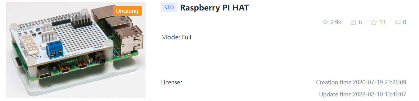
Figure: Raspberry Pi hat
A HAT can be thought of as a special “backpack” for the Raspberry Pi that connects directly to the top of the board. Instead of dealing with jumper wires and breadboards, you get a sturdy, compact PCB that sits neatly on the Pi and aligns with its mounting holes. The HAT concept was introduced by Raspberry Pi in 2014 to bring consistency to the add-on board ecosystem. The specification defines important aspects such as the board dimensions, connector, power behavior, and the self-identification EEPROM. Follow these requirements correctly, and your board can become a plug-and-play expansion for Raspberry Pi users.
HAT vs uHAT vs HAT+ vs Non-HAT Add-on Boards
HAT (the original, full-size):
The classic HAT is the same size as the larger Raspberry Pi models (e.g., Pi 3, Pi 4). It supports the full 40-pin header, has a defined board outline, and has an ID EEPROM. This is the “reference” format that most people will be thinking of.
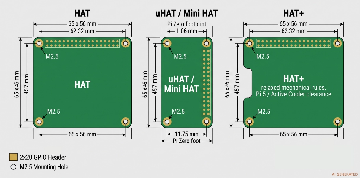
Figure: Comparison of HAT, uHAT, and HAT+
uHAT (mini/half-size):
A uHAT (Mini HAT) is a smaller board, sized to fit over the Raspberry Pi Zero footprint. Still equipped with the 40-pin header and is capable of carrying an EEPROM, but has a smaller outline, making it a fit for low-cost and space-constrained designs.
HAT+ (the current standard for Pi 5):
In December 2023, HAT+ was released with the Raspberry Pi 5. It removes some of the strict mechanical requirements from the original 2014 spec, changes the power and EEPROM requirements, and introduces more features, such as support for the PCIe connector on the Pi 5.
Non-HAT Add-on Boards
You can absolutely build a board that plugs into the GPIO header without an EEPROM or the exact outline. It simply cannot legally call itself a "HAT." These are perfectly valid for personal projects and prototypes.
| Board type | GPIO connector | Mounting holes | ID EEPROM required? | Target Pi models |
|---|---|---|---|---|
| HAT (full-size) | 40-pin 2×20 | 4 × M2.5 | Yes | Pi 2/3/4 (Model B/A+) |
| uHAT (mini) | 40-pin 2×20 | 2–4 × M2.5 | Recommended | Pi Zero / Zero 2 W |
| HAT+ | 40-pin 2×20 | M2.5 (relaxed rules) | Yes (updated spec) | Pi 5 (and back-compatible) |
| Non-HAT add-on | 40-pin (or fewer) | Optional | No | Any with a 40-pin header |
Before You Design — The GPIO Header and Pinout
Everything on a HAT connects through the 40-pin GPIO header, so this is where your design conversation begins. The header is a 2×20 arrangement with a 2.54 mm pitch, giving you 40 pins in two rows of 20.
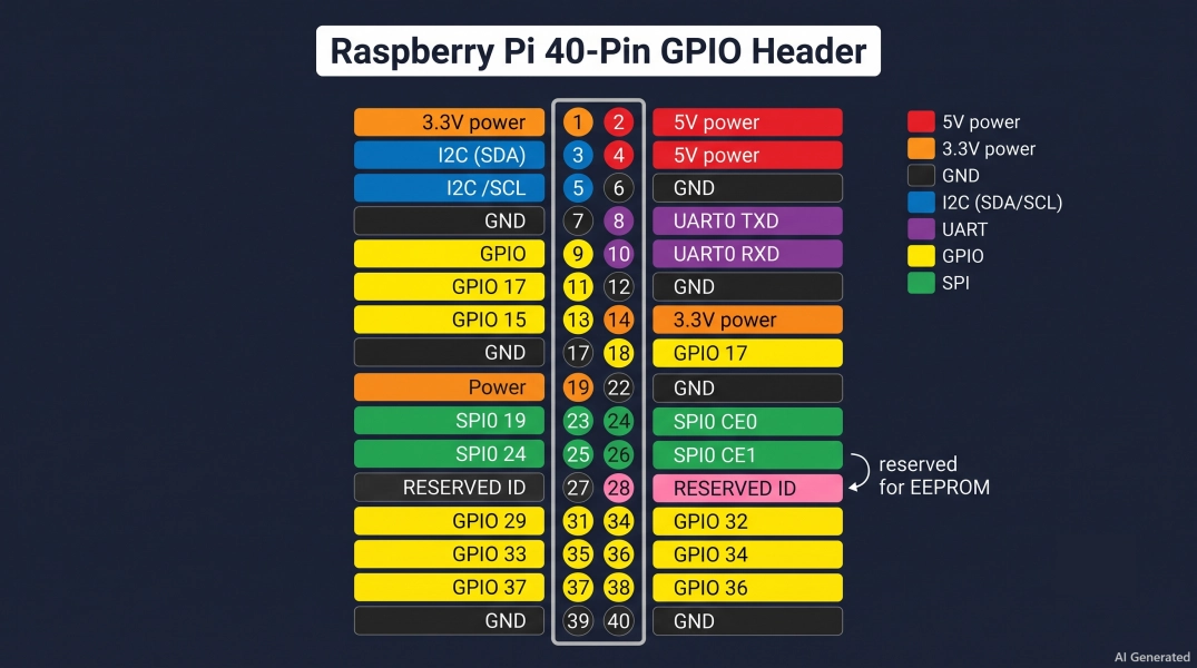
Figure: Raspberry Pi GPIO headers
Those 40 pins are not all general-purpose. Some carry power, some are ground, some are dedicated buses, and two are set aside for board identification. Here is how they split up:
- Power rails: two 5V pins and two 3.3V pins to power your board's electronics.
- Ground: eight GND pins spread across the header for solid return paths.
- I2C: GPIO2 (SDA) and GPIO3 (SCL) for sensors and peripherals.
- SPI: GPIO7–GPIO11 provide the SPI bus for fast peripherals like displays and ADCs.
- UART: GPIO14 (TXD) and GPIO15 (RXD) for serial communication.
- General GPIO: the remaining pins are flexible digital I/O you can assign however you need.
Step-by-Step — How to Design a Raspberry Pi Expansion Board
Now for the heart of it. Here is a repeatable six-step flow you can follow every time you design a Raspberry Pi expansion board, from a blank page to a finished layout.
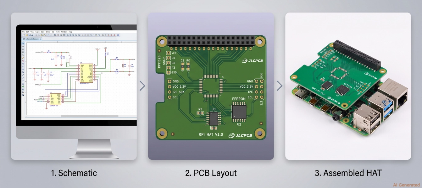
Figure: Raspberry Pi expansion board design from schematics to PCB and assembly
Step 1: Define your requirements and subsystems: Decide what you want on the board as per the application: motor driver, sensor hub, audio DAC, power supply, then make a list of every function block. Map each block to the GPIO pins, buses, and power rails it needs.
Step 2: Start with a board outline template: Do not outline by hand from scratch; begin with a mechanical template that already includes the correct board shape. This will help to align the 40-pin header footprint and the mounting holes with the actual Pi. The Raspberry Pi template is attached at the end of this tutorial.
Step 3: Capture the schematic: Place your 2×20 header symbol, connect the power rails and ground, then wire up your subsystems to the appropriate GPIOs. Keep a clear net-naming convention (Relaxed/variable MOSI), so the layout stage stays sane.
Step 4: Design the power tree: Decide how each part gets powered, either directly from the 5V/3.3V rail or through a local regulator you add. Budget your current draw against what the Pi can supply, and add decoupling capacitors at every IC.
Step 5: Add the ID EEPROM circuit: Wire a 24Cxx-type EEPROM to the ID_SD/ID_SC bus with the correct pull-ups. This is what promotes your board from "add-on" to "official HAT" and enables auto-configuration.
Step 6: Layout the PCB: Place the header and mounting holes first (because they are fixed), then arrange components for clean routing. Keep high-current traces wide, decoupling caps close to their pins, and the EEPROM near the ID pins.
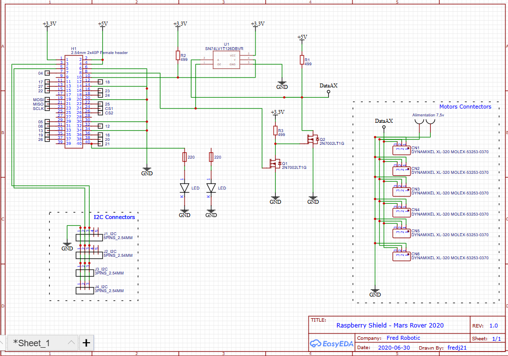
Figure: Open source schematic of Raspberry Pi expansion board by fredj21
A great way to see the whole flow in practice is to study an open-source build. The Raspberry Pi HAT project by fredj21 on OSHWLab is a clean, complete example: you can open the schematic and PCB side by side and trace exactly how the header, power, and peripherals come together.
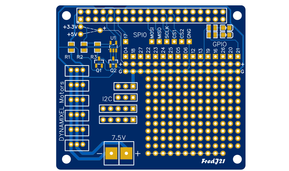
Figure: Open source PCB of Raspberry Pi expansion board by fredj21
Mechanical Design — Board Size, Mounting Holes, and Spacing
A HAT must physically fit the Raspberry Pi, so mechanical requirements come first and are non-negotiable. The original full-size HAT outline is 65 mm × 56 mm, with rounded corners on the two edges opposite the GPIO header.
Board-to-board spacing is also important, especially with the Raspberry Pi 5. The original HAT specification assumed a standoff height of approximately 10–12 mm. HAT+ allows more clearance and recommends around 15–16 mm. This additional space ensures that accessories, such as the Pi 5 Active Cooler, have enough room beneath the HAT.
| Parameter | Original HAT | HAT+ (Pi 5 era) |
|---|---|---|
| Board outline | 65 × 56 mm | Relaxed/variable |
| Mounting holes | 4 × M2.5 | M2.5, aligned to Pi |
| Corner radius | Defined (rounded) | Relaxed |
| Board-to-board spacing | 10–12 mm | 15–16 mm (Active Cooler clearance) |
| GPIO overhang | Not over USB/Ethernet | Not over USB/Ethernet |
Power Design — 3.3V, 5V, and Back-Powering the Pi
Power is where plenty of first HATs go wrong, so let us be precise. Your board can draw power from the header or, in some cases, feed power back into the Pi.
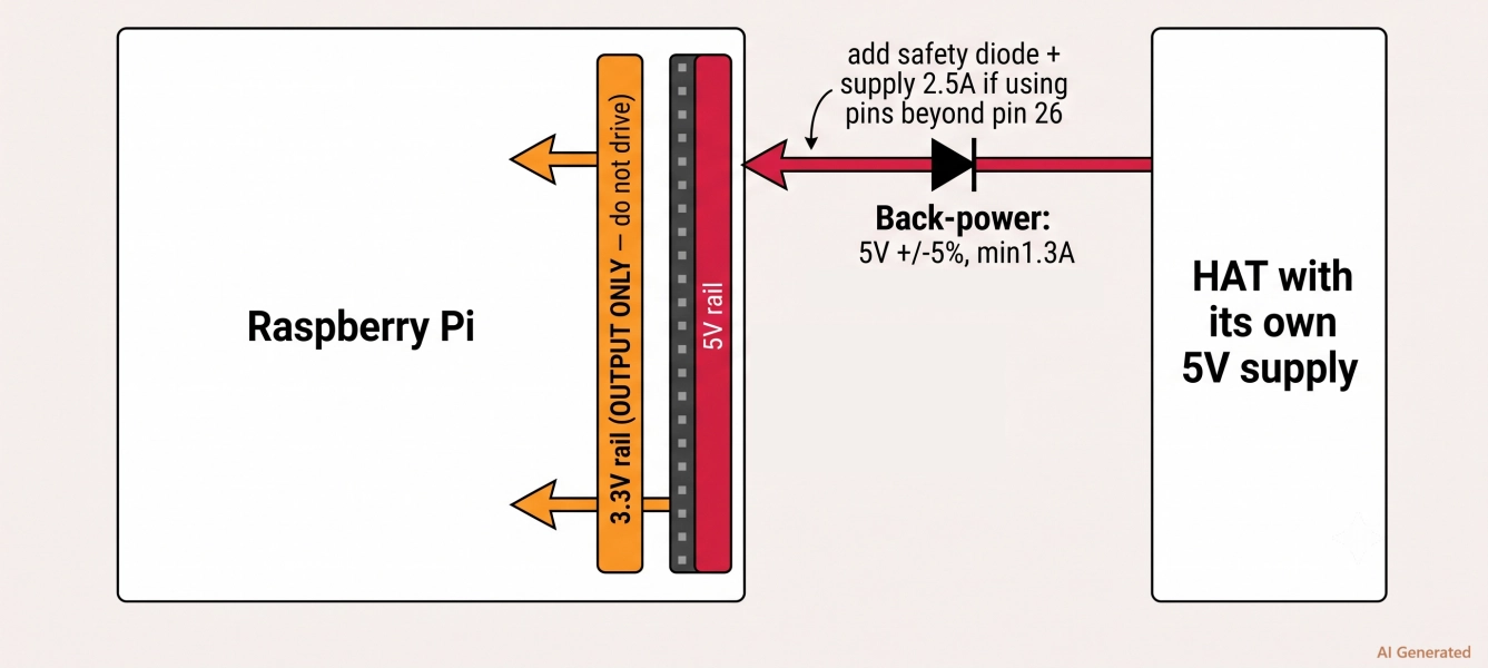
Figure: Power supply guidelines for Raspberry Pi
The header exposes 5V and 3.3V rails. The 5V rail is the strong one and ties to the Pi's main input. The 3.3V pins are output-only, and they come from the Pi's on-board regulator, so the current is limited, and you must never attempt to drive power into them.
Back-Powering the Pi
Back-powering provides power to the 5V pins on the header, powering the entire Pi from your HAT. Specifically, this will need to be 5V and capable of sourcing at least 1.3A (2A recommended).
A few golden rules for HAT power design:
- Never feed voltage into the 3.3V pins.
- If you back-power, hold the 5V rail tightly at 5V ±5% under load.
- Add a series safety diode when your board can be powered both from the Pi and from its own input.
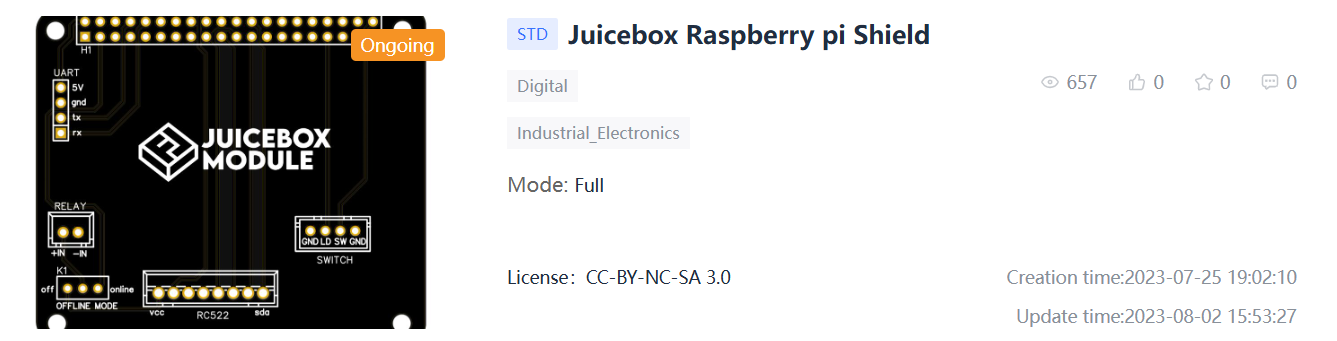
Figure: Open source Juicebox Raspberry Pi shield design by crazydna
If you want to see a power-focused board, look at the JuiceBox RPi shield by crazydna on OSHWLab. It is an open-source power board for the Pi, and its schematic and layout show how a real design handles the 5V feed and protection around the header.
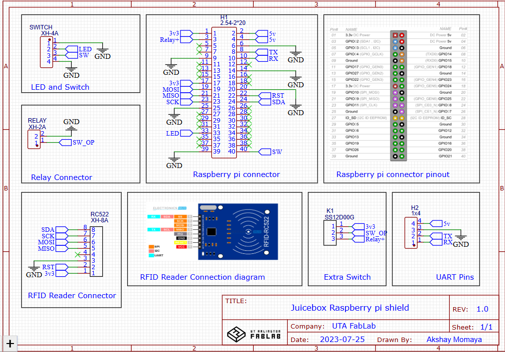
Figure: Juicebox Raspberry Pi shield schematic by crazydna
Logic Level Shifting (3.3V to 5V)
Raspberry Pi's GPIO pins are 3.3V logic and are not 5V-tolerant. If you apply 5V directly to a GPIO input, you can damage the input pin, or even the entire SoC. There’s no need for a level shifter when all the devices on your HAT operate at 3.3 V. However, if you need to communicate with a 5 V sensor, display, or logic device, you’ll need a level shifter to translate signals between the two voltage levels safely.
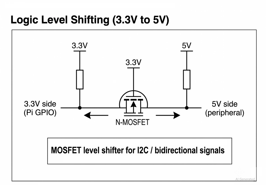
Figure: Logic level shifting schematic for Raspberry Pi GPIO.
The standard solution is to use a bidirectional level shifter. A common and cost-effective approach is to use one N-channel MOSFET per signal line, with pull-up resistors connected to each voltage rail. The low-voltage side is pulled up to 3.3 V, while the high-voltage side is pulled up to 5 V. The MOSFET then allows the signal to pass in both directions.
This approach is particularly well-suited to I²C, because I²C uses open-drain, bidirectional signaling. It allows devices operating at different voltage levels to communicate safely without forcing either side to operate outside its specified voltage range.
The ID EEPROM — Making It an Official "HAT"
This is the piece that turns a plain add-on board into a genuine HAT. The ID EEPROM is a small non-volatile memory chip that stores a description of your board: its name, GPIO map, and device-tree information, so the Pi can read it at boot and configure itself automatically.
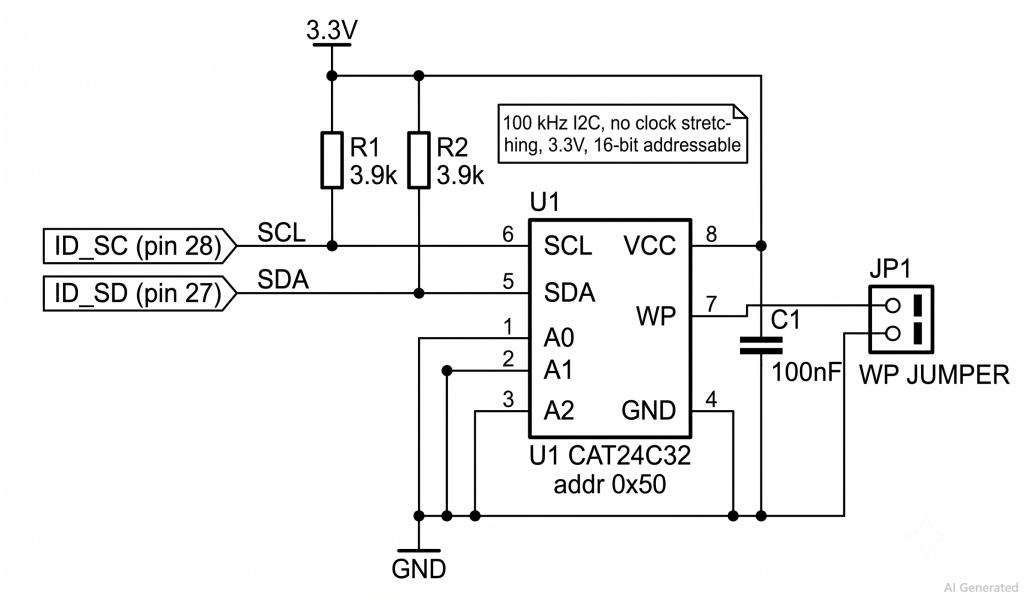
Figure: Raspberry Pi EEPROM configuring schematics.
The specification is very precise about the EEPROM, and getting these details right is essential for reliable automatic HAT detection. The EEPROM is connected to the reserved ID_SD/ID_SC bus (pins 27 and 28) and must meet the following requirements:
- Type: a 3.3V, 16-bit-addressable 24Cxx-style EEPROM (e.g., 24C32 or larger).
- I2C address: 0x50 on the ID bus.
- Bus speed: 100 kHz I2C, with no clock stretching.
- Pull-ups: 3.9 kΩ resistors on both ID_SD and ID_SC to 3.3V.
- Write protect: a write-protect provision so the ID data cannot be corrupted by accident.
| Requirement | Specification |
|---|---|
| EEPROM type | 24Cxx, 3.3V, 16-bit addressable |
| Recommended part | CAT24C32 (32 kbit) |
| I2C address | 0x50 |
| Bus | ID_SD / ID_SC (pins 27 / 28) |
| Clock speed | 100 kHz, no clock stretching |
| Pull-up resistors | 3.9 kΩ to 3.3V (both lines) |
| Write protect | Required (jumper or GPIO controlled) |
A board without an EEPROM still works electrically. It just cannot officially be called a HAT and will not auto-configure. If full compliance is your goal, this chip is worth the few extra cents.
Designing in KiCad and EasyEDA (with Templates)
You don’t need expensive software to design a Pi HAT. If you’re looking for a free and capable solution, two options cover most needs: KiCad, which is open-source and cross-platform, and EasyEDA, which is browser-based and offers a large parts library.
Whichever tool you choose, start with a template rather than a blank canvas. Community-maintained HAT templates for both KiCad and EasyEDA already include the 65 × 56 mm board outline, M2.5 mounting holes, and 2×20 GPIO header footprint. Using one of these templates is the quickest and easiest way to ensure your design is mechanically compliant with the Raspberry Pi HAT form factor.
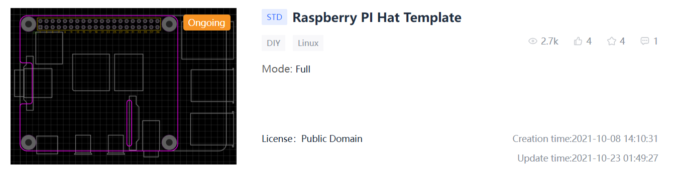
Figure: Open source template for Raspberry Pi hat by Vista
For EasyEDA users, the Raspberry Pi HAT template by Vista on OSHWLab is a ready-made starting point. Just open it, clone it into your workspace, and the outline, mounting holes, and header are already in place.
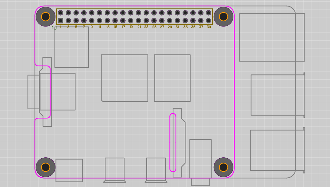
Figure: Raspberry Pi hat design template
A few practical tips for the design stage:
- Use the correct female 2×20 socket footprint so your HAT plugs down onto the Pi.
- Name your nets clearly and match them to the GPIO functions.
- Run the design-rule check (DRC) early and often, not just at the end.
Design for Manufacturing (DFM) and Getting Your HAT Made
You have a schematic and a layout, now it's time to make it real without surprises. Design for Manufacturing (DFM) means laying out the board so it can be fabricated and assembled cleanly, at low cost, and with high yield.
Before you export anything, run through a short DFM checklist:
- Respect minimum design rules
- Check silkscreen
- Confirm connector orientation
- Add fiducials
- Panelize
Once the layout passes, export the standard manufacturing files: Gerbers (copper, mask, and silk layers), the BOM (parts list), and the CPL/pick-and-place file (component positions and rotations).
You can upload your Gerbers to JLCPCB for an instant quote, get bare boards for as little as $2, and add PCBA (SMT assembly) so your HATs arrive with the EEPROM, level shifters, and connectors already soldered. EasyEDA integrates directly with the JLCPCB Parts Library, making it easy to move from PCB design to fully assembled boards with just a few clicks.
Common Mistakes When Designing a Raspberry Pi HAT
Even experienced designers fall into the same few problems. Look for these, and your first HAT will most likely be successful on your first attempt:
- Wrong header: Your HAT physically does not fit into the Pi because you used the wrong header (male header vs. female 2×20 socket).
- Reserved ID pins: Pins 27/28 (ID_SD/ID_SC) drive reserved ID pins and are used only by the EEPROM.
- Using an 8-bit-addressable EEPROM: The spec calls for a 16-bit-addressable 24Cxx part; 8-bit won't be read correctly.
- Do not apply 5V to a GPIO: The Pi's GPIO is 3.3V only and not 5V tolerant.
- No pull-ups or incorrect pull-ups: The ID bus should be pulled up with 3.9 kΩ; otherwise, the EEPROM will not work.
- Feeding power to the 3.3V pins: These pins are output-only; don't drive them, or you may damage the Pi's regulator.
Conclusion
The idea of creating an expansion board for the Raspberry Pi can seem difficult at first, especially with so much information and documentation already available. However, the process can be broken down into six clear steps: requirements, template, schematic, power, EEPROM, and layout.
Once you understand this workflow, you can apply the same process to almost any project: a motor HAT, a sensor HAT, or a custom expansion board of your own design. Once your PCB layout is complete, you can export the Gerber files, BOM, and CPL files, send them to JLCPCB, and get an instant manufacturing quote. In just a few days, your design can go from a PCB file on your computer to fully assembled, working hardware.
FAQ
Q: What is a Raspberry Pi HAT?
A Raspberry Pi HAT (Hardware Attached on Top) is an add-on board that plugs onto the Pi's 40-pin GPIO header to extend its functionality. It follows a defined mechanical outline, uses a standard 2×20 connector, and includes an ID EEPROM so the Pi can auto-detect and configure the board at boot.
Q: What is the difference between a HAT and a uHAT?
A full-size HAT (65 × 56 mm) matches the larger Raspberry Pi models, such as the Pi 3 and Pi 4. A uHAT (Mini HAT) is a smaller board sized for the Raspberry Pi Zero footprint. Both use the 40-pin header and can accommodate an EEPROM; the main differences are physical size and the target Pi model.
Q: Do I need an EEPROM to make a HAT?
Yes, if you want a compliant, officially named HAT. The ID EEPROM stores your board's details so the Pi can auto-configure at boot. A board without one works electrically and is fine for personal projects, but it cannot be called a HAT and will not auto-detect. Use a 24Cxx part at address 0x50.
Q: Can I power the Raspberry Pi through the GPIO header?
Yes, this is called back-powering. Feed 5V into the header's 5V pins at 5V ±5% and supply at least 1.3A (2A+ recommended). If you use GPIO pins beyond pin 26, supply 2.5A and add a safety diode. Never apply power to the 3.3V pins, as they are output-only.
Popular Articles
• PCB Silkscreen: All You Need to Know
• The Comprehensive Guide to Circuit Symbols: Key to Understanding Electrical and Electronic Diagrams
• Design Guidelines for PCB Using FR4 Substrates
• Choosing the Best PCB Color-Enhancing Aesthetics and Functionality
• PCB Board Design: A Step-by-Step Guide for Beginners
Keep Learning
ESP32 Power Consumption Explained: Current Draw, Sleep Modes, and Battery Life
Key Takeaways Power consumption by mode: The ESP32 draws around 240 mA during Wi-Fi transmission, 0.8 mA in light sleep, and just 10 µA in deep sleep, based on Espressif's typical datasheet figures. Deep sleep current: The ESP32 can draw 10 µA in deep sleep, with only the RTC timer and memory remaining powered. Keeping the ULP coprocessor running increases current consumption to around 100–150 µA. Development board power consumption: A typical ESP32 development board can draw around 6.5 mA even in dee......
ESP32 Pinout Reference: Which GPIO Pins Are Safe to Use and Avoid?
Key Takeaways GPIO count: The ESP32 chip has 34 GPIOs, and the ESP32-WROOM-32E module exposes 26 of them. General-purpose pins: Fifteen module GPIOs carry no boot, flash, or input-only restrictions: GPIO4, GPIO13, GPIO14, GPIO16 to GPIO19, GPIO21 to GPIO23, GPIO25 to GPIO27, GPIO32, and GPIO33. Strapping pins: GPIO0, GPIO2, GPIO5, GPIO12, and GPIO15 are sampled at reset, so any circuit connected to them must maintain the level required by the boot mode. Input-only pins: GPIO34, GPIO35, GPIO36, and GPI......
PCB Silkscreen: All You Need to Know
Key Takeaways The PCB Silkscreen Guide demonstrates that a properly designed legend layer is essential to prevent assembly failures and ensure long-term hardware reliability. By mastering modern manufacturing methodologies like Direct Legend Printing (DLP) and aligning layouts with JLCPCB's strict DFM design rules—including the absolute 0.8 mm character height limit and the automated 0.15 mm silkscreen clipping protocol driven by solder mask precedence—engineers can seamlessly eliminate cold joints an......
A Beginner's Guide to Basic Electronic Components: Functions, Symbols & Uses
Every circuit, from a simple LED flashlight to a microcontroller board, is built from the same handful of common electronic components. This guide breaks down the ten basic electronic components you will encounter most often: What each component does How it works Key specifications Where engineers use it By the end, you will be able to recognize these electronic circuit components on a schematic, a PCB, or a parts bin, and know exactly why each one is there. These electronic components are the buildin......
How to Read and Create PCB Schematics
Key Takeaways Read Schematics: Understand symbols, net labels, and component values. Design in EasyEDA: Place components and create circuit connections. Run Design Checks: Use ERC and DRC to identify potential issues. Verify Components: Check pin assignments and PCB footprints. Prepare for Manufacturing: Validate PCB layouts and manufacturing files. Printed circuit board (PCB) design begins with a clear understanding of how the electronic circuit should function. A schematic diagram represents the cir......
Maximizing Circuit Reliability with PCB Test Points and Smart DFT
Key Takeaways Early Fault Catching: Test points drastically reduce diagnosis time and prevent costly field failures. Standard Pad Sizing: Use 1.0 mm flat copper pads with 2.54 mm spacing for optimal fixture contact. Protect High-Speed Signals: Keep branch traces short to prevent capacitive loading and resonance. Single-Sided Access: Place all test pads on the bottom layer to cut fixture costs. Right Test for Volume: Use flying probe for prototypes and bed-of-nails ICT for mass production. A PCB test p......