
The Ultimate Fuse Symbol Guide for Schematics, PCB Design & Electrical Protection
16 min
- What Does a Fuse Symbol Look Like in a Circuit Diagram?
- IEC vs ANSI Fuse Symbol - Key Differences
- Symbol for Different Fuse Types
- How to Read Fuse Symbols in Circuit Diagrams
- Common Mistakes When Using Fuse Symbols
- Fuse Symbol in Real Circuit Diagrams (Practical Examples)
- Fuse Symbol vs Real Component
- Fuse Symbol vs Resistor Symbol
- Fuse Symbol vs Circuit Breaker Symbol
- Fuse Symbol in PCB Design
- FAQs
- Conclusion
Key Takeaways About Fuse Symbols
1. Fuse symbol represents overcurrent protection: It shows exactly where the circuit intercepts fault currents.
2. Always placed in series: Never in parallel; it must sit directly on the power rail.
3. IEC and ANSI symbols differ visually: IEC uses a rectangle with inner vertical lines; ANSI uses either a rectangle with a center line or an S-curve.
4. Annotation defines type and rating: Always include designator (F1), blow type (F/T), amps, and volts.
5. Critical for PCB safety and certification: Proper symbol documentation is required by UL and CE standards.
In almost every electrical circuit diagram, you'll find a fuse symbol, a small but critical marking that tells engineers exactly where overcurrent protection is placed. Whether you're reading a schematic for the first time or designing a PCB for production, understanding the electrical fuse symbol, what it looks like, and how to interpret its annotations is a fundamental skill.
This guide covers the schematic symbol for a fuse from the ground up, written for both beginners and working engineers. In this guide, you’ll learn:
1. Fuse symbol meaning in circuit diagrams
2. IEC vs ANSI symbol differences
3. Types of fuse symbols (fast, slow, thermal)
4. How to read fuse ratings and annotations
5. How fuses are used in PCB design
6. Common schematic mistakes to avoid
What Does a Fuse Symbol Look Like in a Circuit Diagram?
The fuse symbol in a circuit diagram varies depending on the standard used, but all versions share the same fundamental idea: a circuit line interrupted by a specific shape representing the consumable fuse element. In practical schematics, the fuse symbol is always placed in series with the power rail.
IEC vs ANSI Fuse Symbol - Key Differences
If you're wondering what a fuse symbol looks like, the exact appearance depends on whether the schematic follows international or North American conventions.
In IEC drawings, you’ll typically see a rectangular symbol with inner vertical lines, while ANSI diagrams often show either a rectangle with a continuous center line or a curved element representing the fuse wire.
Recognizing these distinct forms is essential when working across international designs.
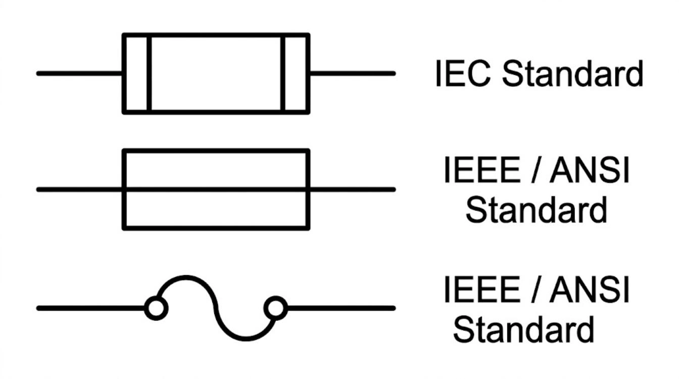
Figure: Showing the IEC standard fuse symbol alongside the two IEEE ANSI standard fuse symbols.
IEC Fuse Symbol (IEC 60617 Standard)
The IEC standard utilizes a boxed shape where the connection lines meet the outer edges of the box, featuring inner vertical lines or small segmented blocks near the ends. This abstract geometric shape is heavily favored in European, Asian, and global product schematics.
ANSI Fuse Symbol (IEEE/ANSI Standard)
The IEEE/ANSI standard is unique because it offers two accepted forms. The first is a rectangular box with a continuous line passing straight through the middle. The second is a more descriptive representation of the physical wire utilizing an S-curve or loop with small terminal circles. Both are primarily utilized in the United States and Canadian engineering sectors.
| Feature | IEC (IEC 60617-7) | ANSI / IEEE (Y32.2) |
|---|---|---|
| Appearance | Rectangle with inner vertical lines near ends | Rectangle with center line OR S-curve element |
| Used in | Europe, Asia, global products | United States, some Canadian designs |
| Shape philosophy | Boxed, segmented | Boxed with continuous line or descriptive wavy wire |
| Standard body | International Electrotechnical Commission | IEEE / American National Standards Institute |
Which Fuse Symbol Standard Should You Use?
- Designing for international or European markets → use IEC
- Designing for the US market → use ANSI
- Using an EDA tool → check the library standard before mixing symbols across schematic sheets (EasyEDA and KiCad default to IEC; older Eagle libraries often default to ANSI)
Symbol for Different Fuse Types
Not all fuses are identical, and schematics distinguish between them using symbol variants or annotations.
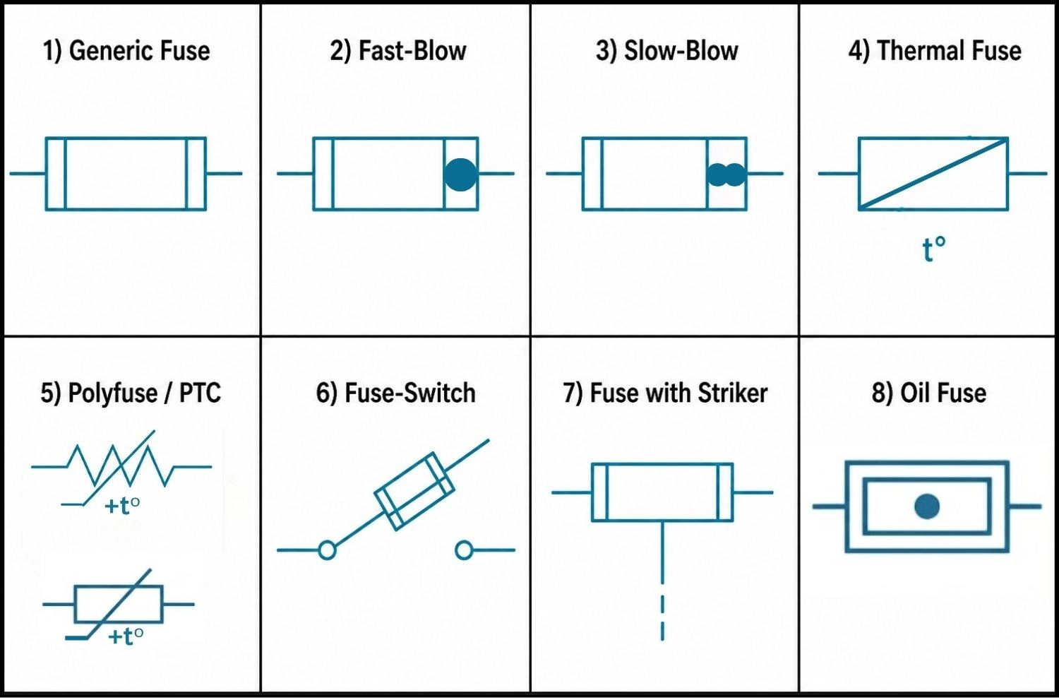
Figure: Eight types of fuse symbol, including generic, fast-blow, slow-blow, thermal, polyfuse PTC, fuse-switch isolator, fuse with striker, and oil fuse.
Generic Fuse Symbol
The standard symbol with no additional markings. Used when fuse type is specified in the BOM separately, or when blow characteristic is not critical to the schematic.
Fast-Blow Fuse Symbol (F / FF)
- Visual Details: In detailed schematics, this is often depicted by an IEC fuse symbol with a solid dot placed inside the right-hand segment of the box.
- Marked "F" (fast) or "FF" (very fast) before the current rating.
- Responds to overcurrent almost instantly, with zero delay.
- Used in precision analog circuits, measurement equipment, and designs that cannot tolerate current surges.
Slow-Blow (Time-Delay) Fuse Symbol (T / TT)
- Visual Details: Visually represented by two filled semi-circles meeting in the middle (resembling an hourglass) inside the right-hand segment of the IEC symbol.
- Marked "T" (time-delay) or "TT" (very slow).
- Tolerates short inrush currents before opening.
- Common in motor drive circuits, switching power supplies, and transformer primaries.
Thermal Fuse Symbol
- Visual Details: Drawn as a rectangle with a diagonal line passing from the bottom-left to the top-right, accompanied by a "t°" marking below it.
- Responds to temperature, not current.
- Labeled with a trip temperature (e.g., TF 73°C) rather than a current rating.
- Common in appliances like hair dryers, coffee machines, and battery packs.
Polyfuse (PTC Resettable Fuse Symbol)
- Visual Details: Depicted as a standard resistor symbol (either a zigzag line or a rectangular box) with a diagonal line striking through it that features a small flat horizontal base, accompanied by a "+t°" marking.
- Polymeric Positive Temperature Coefficient (PTC) device.
- Trips on excess current-induced heat, then resets automatically when cooled.
- No replacement needed after a fault, as the circuit recovers on its own.
Fuse-Switch Symbol
- Visual Details: Drawn as a switch contact hinging diagonally upwards, with the fuse box drawn directly on the moving hinged line.
- Combines fuse and switch in one symbol, common in industrial panel schematics and distribution boards. Indicates the device can both isolate the circuit and protect against overcurrent.
Fuse with Striker Symbol
- Visual Details: A standard fuse box featuring a vertical line extending downwards from the bottom center, broken by a gap to appear dashed.
- Contains a spring-loaded pin (striker) that deploys outward when the fuse blows.
- Used to actuate a microswitch for remote blown-fuse indication or to trip a multi-pole switch/circuit breaker automatically.
- Primarily found in medium-voltage and high-voltage industrial applications.
Oil Fuse Symbol
- Visual Details: Represented by an outer rectangle enclosing a smaller inner rectangle, with the circuit line passing through and a solid dot in the very center.
- Represents a fuse where the melting element is fully immersed in an oil bath to safely quench high-voltage arcs.
- Used almost exclusively in high-voltage power distribution networks and substations.
How to Read Fuse Symbols in Circuit Diagrams
Reading fuse symbols is essential for troubleshooting and safe system design. Follow these steps to interpret them accurately.
1. Locate the Fuse Symbol
Fuse symbols are placed in series with the protected circuit, typically near the power source or sub-circuit input. Tracing the path shows which downstream components it protects.
2. Confirm the Fuse Symbol Standard (IEC vs ANSI)
Check the diagram's legend. Knowing whether it uses IEC (rectangular boxes) or ANSI/IEEE (S-curves or center-lined boxes) prevents confusing fuses with resistors.
3. Identify the Fuse Type from Graphical Features
Examine the core shape and any extra graphical elements attached to it. These visual cues dictate how the fuse operates:
- Plain symbol: General-purpose protection.
- Dots or Hourglasses: Indicate fast-blow (solid dot) or slow-blow (hourglass) characteristics.
- Diagonal lines or "t°": Point to thermal fuses or resettable PTC devices.
- Mechanical additions: Elements like switch contacts (fuse disconnector), auxiliary signaling contacts, or striker pins indicate monitoring, isolation, or mechanical tripping functions.
4. Decode the Ratings and Annotations
Finally, read the alphanumeric labels placed next to the symbol. This text dictates the physical component's specifications:
- Reference Designators (F, FU): Modern EDA tools use designations like F1 or F2, while older industrial diagrams often use FU1.
- Current Rating (A): The maximum safe operating current (e.g., 2A).
- Voltage Rating (V): Must safely exceed the circuit's supply voltage (e.g., 250V) to ensure safe breaking capacity.
- Blow Type Behavior: Usually marked with 'F' (fast-acting) or 'T' (time-delay/slow-blow).
Example: Decoding a Complete Fuse Annotation
F1 T 1.6A 250V
Reads as: Fuse 1 | Time-delay (slow-blow behavior) | 1.6A current rating | 250V voltage rating
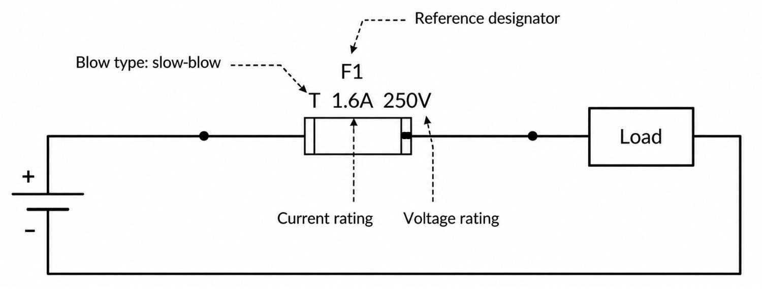
Figure: Annotated fuse symbol in a circuit diagram explaining the F1 reference designator, slow-blow type, current rating, and voltage rating
Common Mistakes When Using Fuse Symbols
These appear repeatedly in design reviews, manufacturing handoffs, and certification audits.
Mixing IEC and ANSI Standards
Contract manufacturers and certification reviewers expect one consistent standard throughout. Mixed schematics slow down review and create component sourcing ambiguity.
Missing Voltage Ratings
Current rating gets attention, while voltage rating often doesn't. A fuse with an insufficient voltage rating can arc internally during a fault rather than clearing cleanly.
Wrong Fuse Type (F vs T)
Same current rating, wrong type: the fuse will either blow on normal startup inrush or fail to protect fast enough. The F / T annotation in the schematic exists specifically to prevent this.
Incorrect Placement in Circuit
Both terminals must connect to different nets. Same net on both terminals means the fuse is shorted out and provides no protection. ERC usually catches this, but verify manually.
Ignoring Resettable Fuses (PTC)
For USB-powered or battery-powered consumer designs, a PTC resettable fuse is often the right choice. Many designers default to a standard fuse symbol without considering that a self-resetting device serves the end user better.
Fuse Symbol in Real Circuit Diagrams (Practical Examples)
Seeing a fuse symbol in isolation is useful, but understanding how a fuse symbol in a circuit diagram behaves in real applications gives practical clarity.
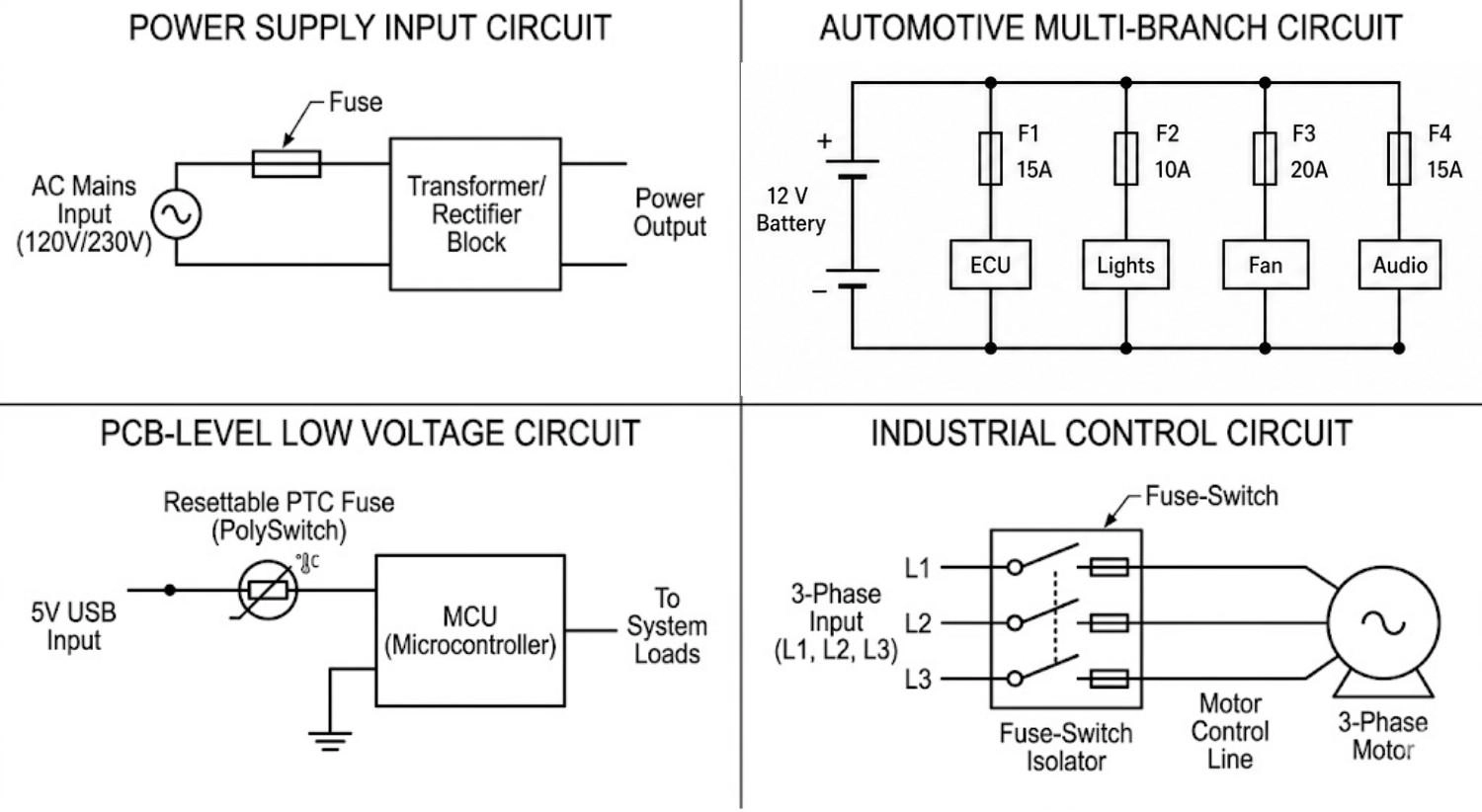
Figure: Examples of fuse symbols placed in power supply, automotive, low voltage PCB, and industrial control circuit diagrams
Fuse Symbol in Power Supply Circuits
In power supplies (SMPS, adapters, chargers), the fuse symbol is placed at the input stage to protect the entire system.
- Positioned in series with AC/DC input
- Located before transformers or regulators
- Protects the entire downstream circuit
Fuse Symbol in Automotive Circuits
Automotive systems distribute power from a central battery to multiple subsystems, each requiring protection.
- Each branch includes a dedicated fuse
- Common in headlights, ECU, infotainment
- Prevents a fault from affecting the entire vehicle
Fuse Symbol in PCB-Level Protection (Low Voltage)
In USB-powered devices and embedded systems, resettable fuses are widely used.
- Uses PTC / polyfuse symbols
- Automatically resets after fault
- Eliminates manual fuse replacement
Fuse Symbol in Industrial Control Circuits
Industrial systems handle high current and require both protection and isolation.
- Often combined with switch (fuse isolator)
- Used in motor drives and control panels
- Enables safe maintenance and shutdown
Fuse Symbol vs Real Component
The fuse symbol in a circuit diagram represents function, not physical form. In real designs, the same symbol maps to very different components depending on the application and environment.
Figure: Comparison of standard schematic fuse symbols with realistic illustrations of a glass tube fuse, SMD chip fuse, automotive blade fuse, PTC polyfuse, thermal fuse, and HRC industrial fuse.
Glass Tube Fuse vs Schematic Symbol (Through-Hole)
In mains and high-voltage applications, the schematic fuse symbol often represents a cylindrical glass tube fuse (e.g., 5×20 mm) with metal end caps.
- Uses through-hole fuse clips or holders
- Easily replaceable by users
- Common in power supplies, appliances, AC input stages
SMD Fuse vs Schematic Symbol (Surface-Mount)
In compact electronics, the same schematic fuse symbol maps to an SMD chip fuse that resembles a small resistor or capacitor.
- Available in 0603, 0805, 1206 packages
- Mounted directly on the PCB
- Not user-replaceable after soldering
Automotive Blade Fuse vs Schematic Symbol (High-Current)
In automotive and DC power systems, the fuse symbol represents a blade fuse with a plastic housing and metal prongs.
- Used in 12V/24V systems
- Color-coded for current rating
- Mounted via blade fuse holders or sockets
Fuse-Switch Isolator vs Schematic Symbol (Industrial Disconnect)
The fuse-switch symbol represents a disconnect unit that houses replaceable fuse links internally. While the schematic looks like a simple switch hinging over a fuse box, the physical component often looks very different.
- Physically resembles a modular miniature circuit breaker (MCB) but houses replaceable fuse links internally.
- Operated via a front-facing plastic lever or handle to safely open the circuit and access the fuse.
- Common in DIN-rail panels, main switchboards, and motor control centers.
Fuse with Striker vs Schematic Symbol (Mechanical Trip)
The schematic symbol with the downward line translates to a large, specialized cylindrical fuse containing a spring-actuated pin.
- The striker pin physically ejects from the end of the fuse when it blows
- Physically hits an adjacent microswitch to trigger remote alarms or trip a larger circuit breaker
- Common in medium and high-voltage switchgear environments
Oil Fuse vs Schematic Symbol (High Voltage)
The boxed-in oil fuse symbol maps to a physical component that resembles a heavy-duty cylindrical ceramic cartridge with thick metal end caps and distinct rubber O-ring seals.
- Designed to be installed and fully submerged within an oil-filled switchgear enclosure
- The oil bath suppresses and quenches massive electrical arcs safely
- Primarily used in utility substations and medium-to-high voltage power distribution
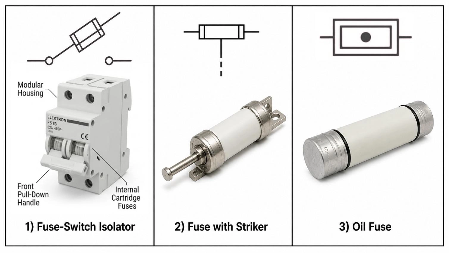
Figure: Comparing schematic fuse symbols with realistic illustrations of a fuse-switch isolator, a fuse with a striker, and an oil fuse.
Fuse Symbol vs Resistor Symbol
The most common misread in schematics occurs between fuses and resistors, especially when switching between IEC and ANSI drawings.
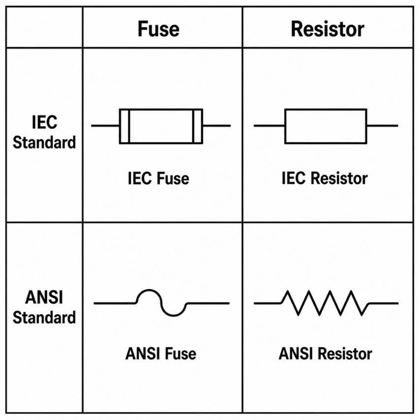
Figure: Comparison of IEC and ANSI fuse symbols with their corresponding resistor symbols
| Feature | Fuse | Resistor |
|---|---|---|
| IEC symbol | Rectangle with inner vertical lines | Rectangle, no inner lines |
| ANSI symbol | Rectangle with center line OR S-curve element | Zigzag line |
| Reference designator | F (e.g., F1) | R (e.g., R1) |
Functional Differences between Fuse Symbol vs Resistor Symbol in Circuits
While a fuse opens permanently on overcurrent to protect the circuit, a resistor remains in the circuit, actively resisting current and dissipating energy as heat.
Note
How to Avoid Misinterpretation
Always check the reference designator: F means fuse, R means resistor. Never rely on symbol shape alone if the drafting standard is unfamiliar. If you’re comparing protection symbols, it’s also useful to understand how they differ from other components like resistors (see our resistor symbol guide) and diodes (see our diode symbol guide).
Fuse Symbol vs Circuit Breaker Symbol
Both protect against overcurrent, but they operate at different scales and behave differently after a fault.
A fuse uses a rectangle or curved element, while the circuit breaker symbol typically features two terminal circles bridged by an upward-curving arc or a switch contact with a semi-circle trip indicator.
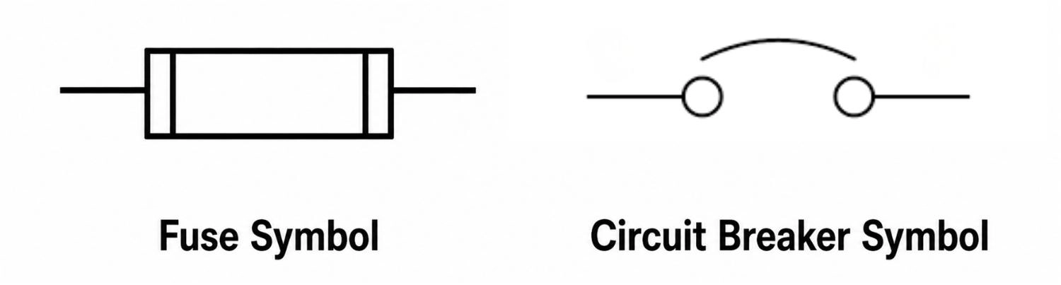
Figure: Side-by-side comparison of a standard fuse schematic symbol and a circuit breaker schematic symbol.
Functional Differences between Fuse and Circuit Breaker (Replace vs Reset)
A blown fuse must be manually replaced with a new component. A circuit breaker represents a resettable device that can be flipped back on manually or automatically.
Note
When to Use Each Protection Device
Fuses are typically located at the PCB level for equipment protection and boast very fast response speeds. Circuit breakers are found at the panel level or in building wiring, and often allow for adjustable selectivity.
Fuse Symbol in PCB Design
In PCB design, the schematic symbol for a fuse is the starting point of a longer workflow, not the endpoint.
Schematic to PCB Workflow (Step-by-Step)
- Place the fuse symbol in your schematic (EasyEDA, KiCad, Altium, Eagle)
- Assign the footprint to match the physical package.
- Set the value (current rating, voltage rating, blow type) in the component properties.
- Run ERC, which confirms the fuse is in series, not floating or bypassed.
Fuse Footprints (SMD vs Through-Hole)
The schematic symbol is package-agnostic. A 0805 chip fuse and a 5×20mm glass fuse use the exact same schematic symbol.
- Through-hole: Fuse_Holder_Keystone_3557 or similar holder
- SMD: Fuse_1206 or Fuse_0805 (chip fuse)
To ensure you have access to the exact components you need, you can browse an extensive library of verified components on the JLCPCB Parts page.
Fuse Placement Guidelines in PCB Layout
- Always place in series on the rail it protects, never parallel.
- Keep it as close to the power entry point as practical, before any rail branching (often modeled similarly to placing a bypass capacitor).
- Through-hole: near board edge, accessible for field replacement.
- SMD: top layer, clearly identified in silkscreen.
From Symbol to Manufacturing (Real-World Workflow)
In professional workflows, schematic symbols are directly translated into manufacturable physical layouts. Once finalized, generate Gerbers. The footprint will be included in the copper and silkscreen layers.
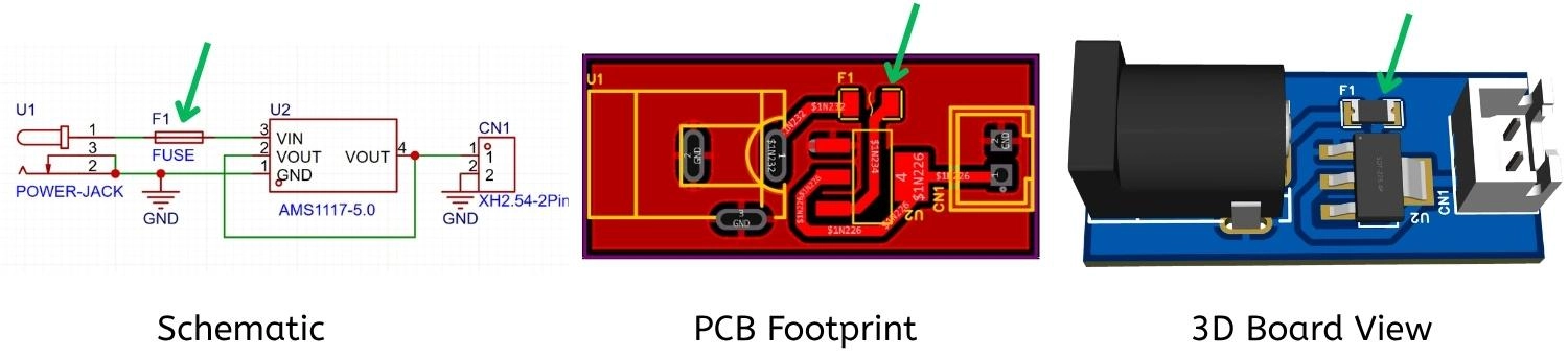
Figure: Showing an identical circuit consisting of a connector, fuse, and IC represented as a schematic symbol, a 2D PCB footprint, and a 3D rendered board view.
With a fast turnaround (24 hours for fabrication), JLCPCB guarantees precision manufacturing so your fuse protection translates flawlessly from schematic to physical board.
Upload Your Gerber Files to JLCPCB → New users get coupons on their first order.
FAQs
Q: What Does a Fuse Do in a Circuit?
A fuse acts as a sacrificial safety device. It protects the circuit from overcurrent conditions (like short circuit or overloads) by melting its internal element and breaking the electrical connection.
Q: What is a fuse symbol in a circuit diagram?
It graphically represents an overcurrent protection device placed in series. Its position, type marking, and annotations dictate how the circuit is protected from fault currents.
Q: What does a fuse symbol look like?
In IEC standards, it is a rectangle with inner vertical lines at the ends. In ANSI/IEEE standards, it is represented either as a rectangle with a continuous center line or an S-curve/wavy line indicating the internal fuse wire.
Q: IEC vs ANSI fuse symbol differences?
The IEC symbol is a geometric, abstract shape favored internationally and in Europe. The ANSI symbol is a descriptive illustration of a wire and is primarily used in North American engineering.
Q: Is a fuse symbol the same as a resistor?
No. While visually similar in IEC diagrams, a fuse (F) interrupts current during a fault and is measured in Amperes. A resistor (R) limits current safely, dissipates heat, and is measured in Ohms.
Q: Why are fuse symbols important in PCB design?
They dictate the physical footprint on the PCB, define safety boundaries, guide BOM generation, and ensure compliance with UL/CE standards during PCBA manufacturing.
Conclusion
Fuse symbols are small on a schematic but carry real weight: standard, type, rating, and placement all matter. Getting them right means fewer sourcing errors, cleaner design reviews, and schematics that communicate precisely to whoever manufactures or certifies the board.
Popular Articles
• How to Create a Bluetooth-Controlled Car With Arduino: A Step-by-Step Guide
• How to Design and Assemble a Reliable ESP32 Module PCB on a 2-Layer Board
• The Ultimate Guide to Relay Symbol: Coil, Contacts, Diagrams, and Circuit Applications
• How to Identify SMD LED Polarity: Markings, Testing, and PCB Tips
• The Ultimate Guide to PCBA: Process,Types and Techniques for the Electronics Enthusiast
Keep Learning
How to Design an ESP32-S3 Development Board from Scratch: A 4-Layer PCB Design Tutorial
Designing your own ESP32-S3 development board gives you complete control over your hardware architecture while preparing your IoT projects for commercial production. Instead of relying on bulkier, off-the-shelf boards, building a custom design allows you to optimize the board space, expose only the required GPIO pins, and integrate peripherals directly onto a single substrate. In this tutorial, we will design a 4-layer ESP32-S3 development board from scratch. We will walk through the entire hardware d......
Arduino LED Driver Tutorial: Control More LEDs with 74HC595 and MAX7219
Arduino GPIO pins run out quickly in larger LED projects. By utilizing dedicated LED drivers and expansion ICs, you can drastically reduce pin usage, eliminate processor-heavy multiplexing loops, and simplify display wiring. In this guide, you will learn the operational architecture, wiring configurations, cascading techniques, and optimization strategies for the 74HC595 shift register and the MAX7219 LED driver. Why Arduino Projects Need LED Driver ICs Arduino GPIO and Current Limitations An ATmega32......
How to Create a Bluetooth-Controlled Car With Arduino: A Step-by-Step Guide
This tutorial walks through the complete engineering and implementation of a two-wheel Bluetooth RC car with an Arduino Nano module on a specially designed PCBA (Printed Circuit Board Assembly). While many hobbyists start by wiring motors and Bluetooth modules with jumper cables on a breadboard, this approach is prone to disconnection and signal noise. This guide upgrades that process by teaching you how to design a professional mainboard. Key Design Features Controller: Arduino Nano used as a plug-in......
Fiducial Marks in PCB and SMT Assembly: A Complete Guide to Accuracy and Design Rules
Modern Printed Circuit Boards (PCBs) are complex, integrating high-density components like 0.4mm pitch Ball Grid Arrays (BGAs), 0201 passives, and fine-pitch Quad Flat No-Lead (QFN) packages. In this advanced manufacturing environment, achieving placement accuracy measured in micrometers is crucial. A significant challenge in automated manufacturing is how pick-and-place machines, which handle thousands of components per hour, precisely locate the PCB. A board on a conveyor system is never in the perf......
Alternating Current vs Direct Current (AC vs DC): What's the Difference?
Electric current flows in two primary forms: alternating current (AC) and direct current (DC). AC periodically reverses direction, while DC flows steadily in one direction. AC powers the industrial and residential electrical grids, while DC powers batteries, electric vehicles, and nearly all modern consumer electronics. Understanding the core differences between AC and DC matters when designing power supplies, selecting electronic components, or laying out printed circuit boards (PCBs). This guide com......
Arduino LED Multiplexing Tutorial: Control More LEDs with Fewer Pins
The Arduino Uno is a powerful tool for prototyping, but driving multiple LEDs directly quickly exhausts its 20 GPIO pins and its 200 mA absolute maximum package current limit. To bypass these hardware bottlenecks, engineers and hobbyists use LED multiplexing to scale display outputs efficiently without upgrading the microcontroller. In this guide, you will learn the core principles of LED matrix scanning, Charlieplexing, refresh timing, ghosting fixes, and practical Arduino code without relying on any......