
The Complete Guide to Transformer Symbol: Meaning, Types, Diagram, and PCB Applications
12 min
- What Is a Transformer Symbol?
- Transformer Symbol Diagram Explained
- Types of Transformer Symbols
- How to Read Transformer Symbols in Circuit Diagrams
- Common Mistakes When Using Transformer Symbols
- Transformer Applications in PCB Circuits
- Transformer vs Inductor Symbol
- Transformer Symbol in PCB Design
- Building Reliable Power Supply PCBs with JLCPCB Fabrication and Assembly Services
- FAQs About Transformer Symbol
- Conclusion
Transformers are fundamental components in power electronics, used for voltage conversion, electrical isolation, impedance matching, and signal coupling. Because of this, the transformer symbol is widely used in circuit schematics for power adapters, SMPS circuits, audio systems, communication interfaces, and industrial electronics.
If you've ever confused it with an inductor symbol or ignored those mysterious dots, this is the transformer symbol explained for you.
In this guide, you will learn:
- Transformer symbol diagram and structure
- Dot convention and winding polarity
- Step-up vs step-down transformer symbols
- Isolation, center-tap, and autotransformer symbols
- How to read transformer symbols in circuits
- Transformer vs Inductor symbol
- Transformer applications in adapters and SMPS
- Transformer symbols in PCB design and layout
- Common transformer symbol mistakes
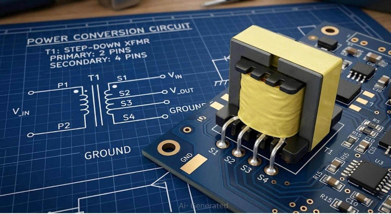
Figure: A transformer schematic symbol on a blueprint with a 3D printed circuit board showing a mounted transformer component.
What Is a Transformer Symbol?
A transformer symbol is a standardized graphical notation used in circuit schematics to represent a transformer component. It visually communicates:
- The number of windings (coils)
- The presence and type of magnetic core
- Polarity of the windings via dot convention
- The relationship between primary and secondary sides
What the Transformer Symbol Represents in a Circuit
The transformer schematic symbol does more than mark a component's location. It defines:
- Energy transfer path - from primary winding to secondary winding via magnetic coupling.
- Electrical isolation - separating the input and output circuits for safety and noise reduction.
- Voltage transformation - step-up, step-down, or 1:1 ratio depending on design intent.
- Signal or power conditioning - whether it handles high-power AC or small audio and data signals.
At a glance, any engineer can look at the electrical transformer symbol in a schematic and immediately understand the circuit's power architecture.
Turns Ratio Representation in Transformer Symbol
The transformer turns ratio (N1:N2) determines how voltage is transformed:
- N1 = number of turns in the primary winding
- N2 = number of turns in the secondary winding
Formula: V1 / V2 = N1 / N2
In a schematic, the number of coil loops drawn on each side indicates this ratio visually. More loops shown on one side signals higher voltage on that winding.
Transformer Symbol Diagram Explained
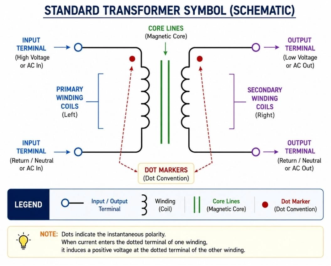
Figure: Standard transformer schematic symbol diagram showing primary coil, secondary coil, core lines, and dot convention markers.
Basic Transformer Symbol (Primary and Secondary Coils)
The standard transformer symbol diagram consists of two core parts:
1. Two sets of coils - each drawn as a series of curved bumps (representing inductance loops).
- Left side = Primary winding (input)
- Right side = Secondary winding (output)
2. Core representation - one or two vertical lines positioned between the coils.
The coils face each other across the core lines. Connections appear at the top and bottom of each winding.
| Element | What It Means |
|---|---|
| Left coil bumps | Primary winding, input side |
| Right coil bumps | Secondary winding, output side |
| Vertical solid lines | Laminated iron or ferromagnetic core |
| No lines between coils | Air-core transformer |
| Dots at winding ends | Polarity reference points |
Meaning of Core Lines in Transformer Symbol
The lines drawn between the two coil sets represent the magnetic core material:
- No lines: Air-core transformer, used in RF and high-frequency circuits.
- One solid line: Ferromagnetic core, iron, or ferrite.
- Two solid lines: Laminated iron core, typical in 50/60 Hz mains transformers.
- Dashed line: Ferrite or powdered iron core, common in SMPS designs.
The core type directly impacts frequency response, efficiency, and power handling capacity. The symbol communicates this without a single additional word.
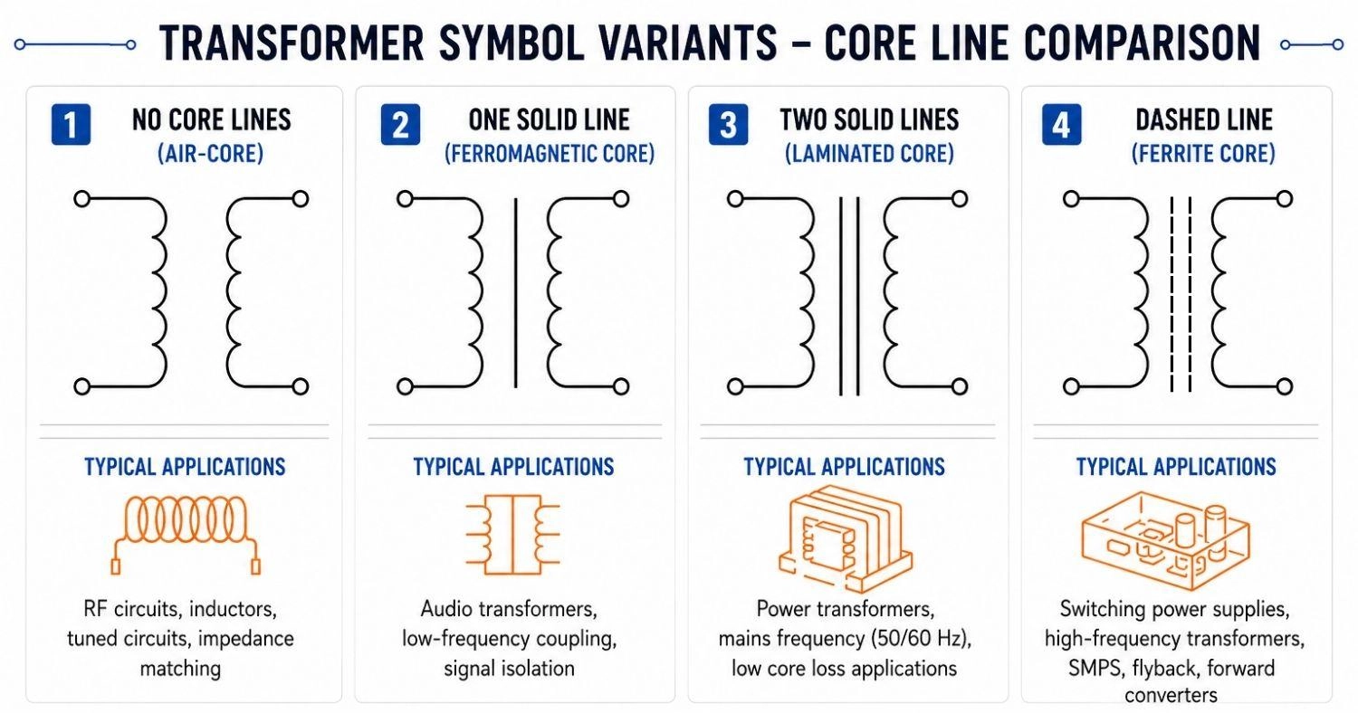
Figure: Four transformer symbol variations showing air-core, single-line core, double-line laminated core, and dashed ferrite core representations.
Dot Convention in Transformer Symbol (Polarity Indication)
The transformer dot convention is one of the most misunderstood aspects of the symbol, and one of the most important to get right.
What the dots mean:
- A dot (•) marks one terminal on each winding.
- When current enters the dotted primary terminal, it exits the dotted secondary terminal.
- This defines the phase relationship between primary and secondary voltages.
Why it matters in practice:
- Incorrect polarity causes destructive interference in parallel windings.
- Audio circuits depend on correct phase for proper signal reproduction.
- Center-tapped rectifiers rely on accurate phase for stable DC output.
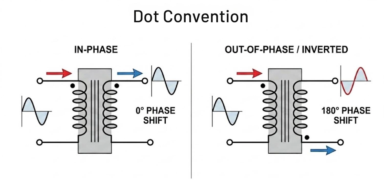
Figure: Showing in-phase and out-of-phase transformer winding configurations based on dot convention placement, including current direction arrows and phase sine waves.
Reading polarity quickly:
- Dots on the same side (both top, or both bottom) - voltages are in-phase.
- Dots indicate relative instantaneous polarity between windings. If wired from opposite sides, the output is inverted (180° out of phase).
Types of Transformer Symbols
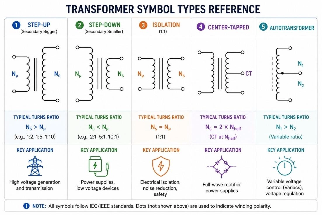
Figure: Five transformer symbol types in circuit diagrams - step-up, step-down, isolation, center-tapped, and autotransformer symbols with labels.
Step-Up Transformer Symbol
The step-up transformer symbol uses the standard symbol with one visual distinction:
- The secondary coil shows more loops than the primary.
- Signals output voltage greater than input voltage.
- Core lines remain the same as standard transformer symbols.
Common applications: Grid-level power transmission, CRT high-voltage generation, ignition coils, inverter output stages.
Step-Down Transformer Symbol
The step-down transformer symbol is the mirror of the step-up:
- Primary coil shows more loops than the secondary.
- Output voltage is lower than input voltage.
- The most common transformer type in everyday electronics.
Common applications: Wall adapters, battery chargers, doorbell circuits, control panel supplies.
Isolation Transformer Symbol
The isolation transformer uses a 1:1 coil ratio with deliberate visual separation between windings:
- Both sides show equal loop counts.
- Some drawings add a wider gap or a barrier mark between the two coils.
- Provides complete galvanic isolation with no direct electrical connection between primary and secondary - ever.
Used for: Equipment and user protection from ground faults, breaking ground loops in audio systems, meeting medical-grade electrical safety requirements.
Center-Tapped Transformer Symbol
The center tap transformer symbol introduces a third terminal:
- A wire branches out from the midpoint of the secondary winding.
- Creates two equal half-windings from one secondary.
Used in: Full-wave rectifier circuits, balanced audio outputs, dual-rail power supplies (e.g., +12V and -12V from one transformer).
Autotransformer Symbol
The autotransformer symbol looks distinctly different:
- Only one winding is drawn, with a tap point along it.
- Primary and secondary share a portion of the same physical winding.
- No electrical isolation between input and output sides.
Used in: Motor soft starters, variable voltage regulators (Variacs), and impedance matching where isolation is not a requirement.
How to Read Transformer Symbols in Circuit Diagrams
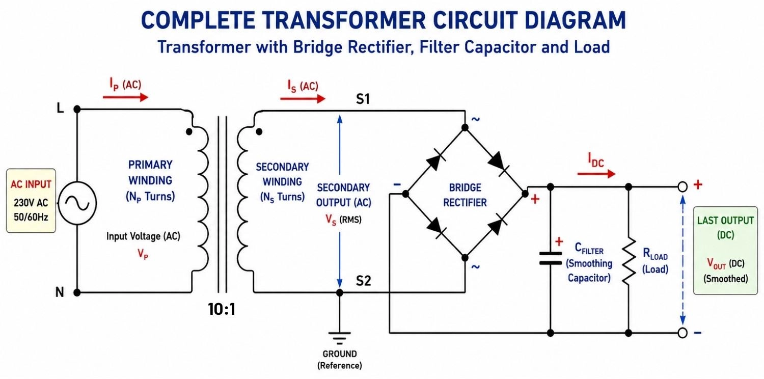
Figure: Transformer circuit diagram showing primary winding connected to AC source and secondary winding driving a bridge rectifier, smoothing capacitor, and load resistor.
Identifying Primary and Secondary Windings
In most schematics:
- The primary (input) side connects to the AC source, typically drawn on the left.
- The secondary (output) side drives the load, typically on the right.
- Labels like "Pri," "Sec," "1:2," or voltage values such as 120V/12V often appear alongside.
Understanding Polarity Using Dot Convention
When analyzing any transformer symbol diagram in a schematic, follow the dot convention to maintain correct phase polarity. Match the dots to ensure your rectifier or load circuit receives the intended in-phase or inverted signal based on your design requirements.
Common Mistakes When Using Transformer Symbols
Ignoring Dot Convention
This is the most common and consequential mistake. Reversed center-tap wiring corrupts the output of a full-wave rectifier, while parallel secondary windings with wrong polarity create a short-circuit loop that destroys windings.
Incorrect Winding Connections
Common wiring errors include connecting the load to the primary side or leaving a center tap floating when the circuit requires it to be grounded.
Transformer Applications in PCB Circuits
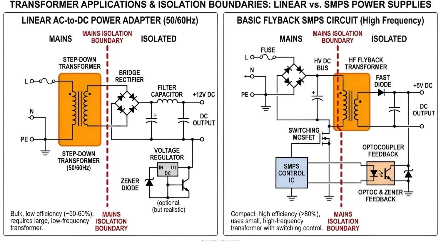
Figure: Real-world circuit examples showing transformer applications and isolation boundaries in a linear power adapter and a switch mode power supply (SMPS).
Transformer in Power Adapters (AC to DC Conversion)
The power transformer symbol is commonly used in mains-powered adapter schematics. A classic use of the transformer in adapter circuits involves:
- Mains AC (120V or 240V) enters the primary winding.
- The step-down transformer reduces voltage.
- Rectifier diodes convert AC to pulsating DC on the secondary side.
- A filter capacitor smooths the output into usable DC.
Transformer in SMPS (Switch Mode Power Supply)
The transformer in SMPS operates on a completely different principle. It runs at a high frequency, typically 20 kHz to 1 MHz, utilizing a ferrite core instead of laminated iron, making it far smaller and lighter.
SMPS transformers offer dramatically smaller footprints and typical efficiencies between 85% and 95%.
Transformer vs Inductor Symbol
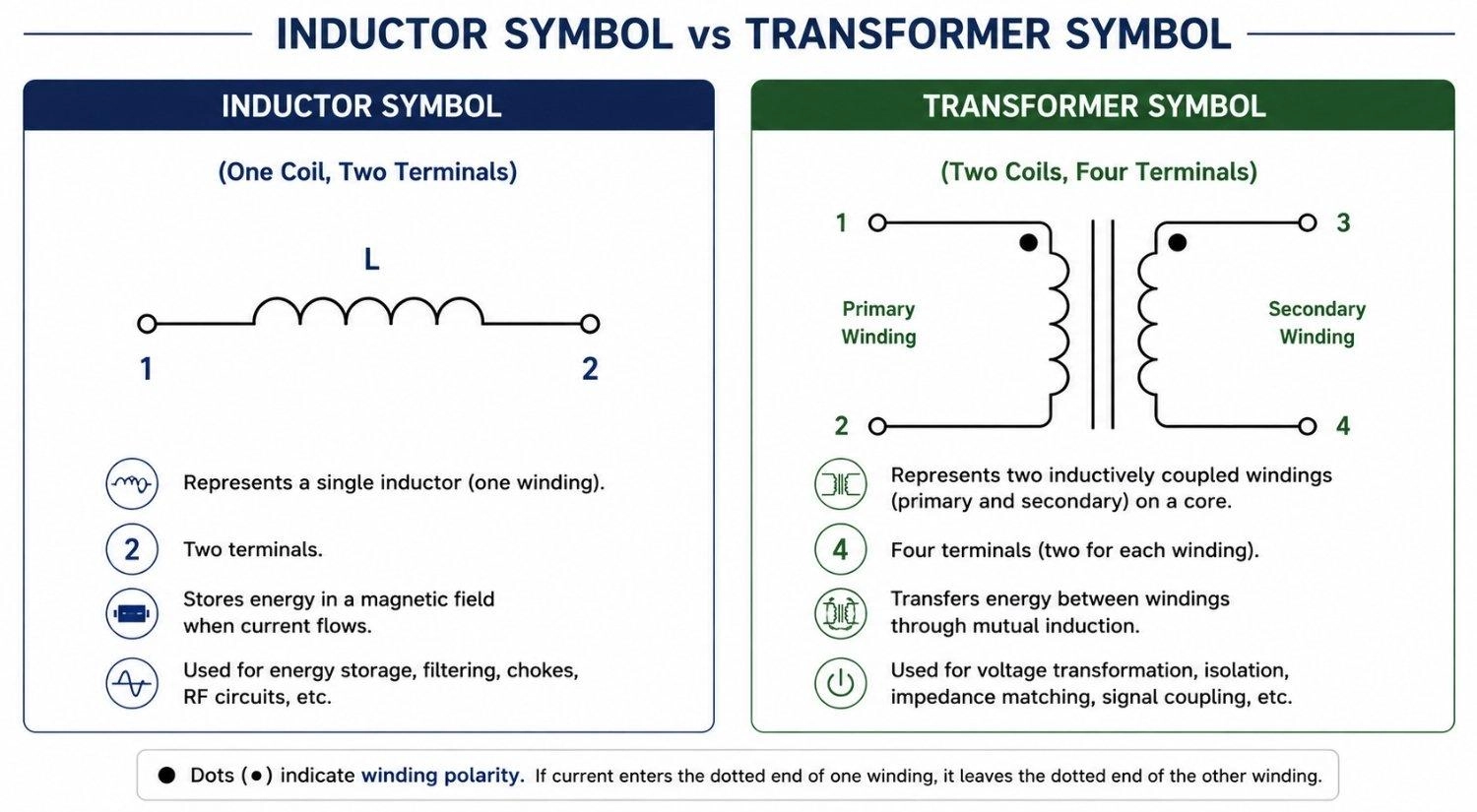
Figure: Schematic symbol comparison showing a two-terminal inductor versus a four-terminal transformer.
While they look visually similar and both rely on electromagnetic principles, their schematic symbols and circuit functions are distinctly different.
Key differences include:
- Coil Count: An inductor consists of a single winding (one row of coil bumps), while a transformer features at least two separate windings (primary and secondary) facing each other.
- Terminal Count: Inductor symbols have exactly two connection terminals. Transformer symbols require a minimum of four terminals.
- Dot Convention: Dots are commonly used on transformer symbols to indicate winding polarity and phase relationship. Standard inductors do not use dot markers.
- Primary Function: Inductors are drawn to represent energy storage within a single circuit path. Transformers are drawn to indicate energy transfer and electrical isolation between entirely separate circuits.
Transformer Symbol in PCB Design
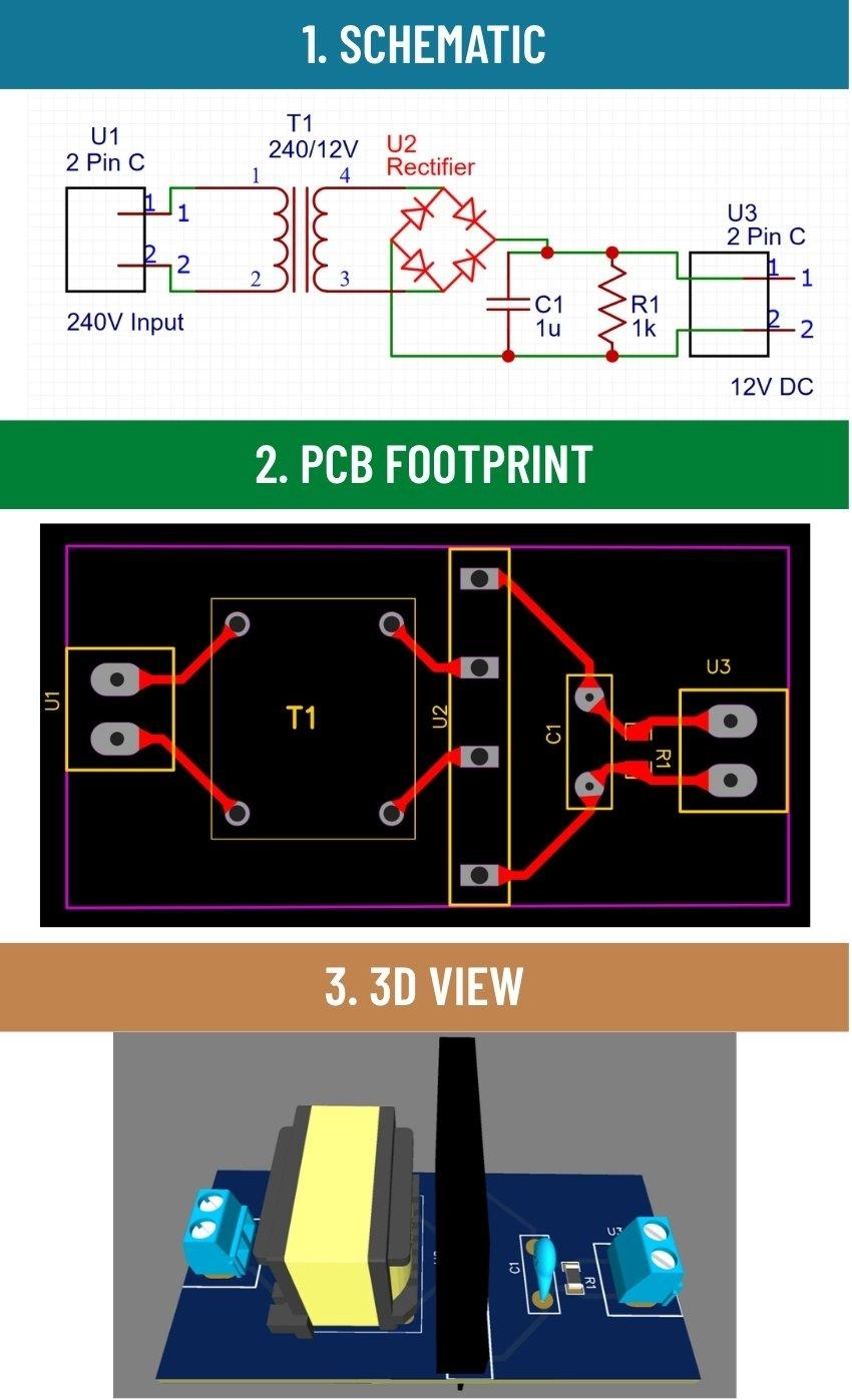
Figure: Showing the progression from a transformer schematic symbol to its 2D PCB footprint with through-holes and finally a 3D rendered PCBA component.
Transformer Symbol vs PCB Footprint
The schematic symbol and the PCB footprint serve completely different roles.
Before moving from schematic to layout, understanding the fundamental difference between a bare PCB and a fully assembled PCBA helps clarify why component footprints must perfectly match physical realities.
| Aspect | Schematic Symbol | PCB Footprint |
|---|---|---|
| Purpose | Shows electrical behavior | Shows physical placement |
| Content | Coils, core lines, dot markers | Pin holes, pad dimensions, courtyard boundary |
| Information | Electrical connections and polarity | Mechanical dimensions and pad geometry |
Mapping Transformer Pins in PCB Layout
When placing a transformer footprint in PCB design, each physical pin maps to a winding terminal from the schematic:
- Pin 1, 2: Primary winding terminals
- Pin 3: Center tap, if present on the transformer
- Pin 4, 5: Secondary winding terminals
Transformer orientation in PCB layout must follow pin mapping and dot convention - misalignment between the schematic dot markers and physical pin placement is one of the most common causes of failed first-article builds.
Isolation and Clearance Considerations
Transformer PCB layouts must meet strict electrical safety requirements:
- Creepage distance: The surface path length between primary and secondary conductors along the PCB.
- Clearance: The shortest straight-line (through-air) distance between conductors.
PCB layout rules
Keep primary and secondary copper traces physically separated. Never route signal or ground traces directly beneath a transformer. For mains-connected designs, mill a slot in the PCB between primary and secondary sides to increase effective creepage distance.
Building Reliable Power Supply PCBs with JLCPCB Fabrication and Assembly Services
PCB Manufacturing for Power Circuits
Transformer-based circuits, particularly power supplies and SMPS designs, come with specific fabrication requirements that standard PCB specifications may not meet by default:
- Fabrication requirements: High-voltage isolation between primary and secondary copper layers requires verified spacing and often a physical slot in the board.
- Spacing and Isolation: Strict adherence to creepage and clearance rules is mandatory to prevent arcing.
- Material Selection: Requires appropriate dielectric materials and High-Tg FR4 for thermal management.
Typical applications include:
- AC-DC adapters
- Flyback converters
- Industrial isolated power supplies
JLCPCB supports 2-layer to 8-layer boards for standard and complex power supply designs, offering High-Tg FR4 materials suited for thermal management in power circuits. You can easily select compatible transformers and related components via the JLCPCB Parts Library.
PCB Assembly for Transformer-Based Designs
Transformers are predominantly through-hole components, making board assembly a mix of technologies. It is crucial to understand the nuances of surface mount vs through-hole constraints when designing your layout.
JLCPCB PCB Assembly services handle mixed-technology boards effortlessly. This includes precise reflow soldering for the surface-mount components surrounding the transformer (like control ICs and MOSFETs), alongside dedicated THT assembly for the transformer itself.
For high-voltage or safety-critical designs, JLCPCB's pre-production design review can identify clearance violations and footprint mismatches before fabrication begins.
FAQs About Transformer Symbol
Q: What Do the Dots Mean in Transformer Symbol?
Dots mark the polarity reference terminal on each winding. When current enters the dotted primary terminal, it exits the dotted secondary terminal. This determines phase relationship and is critical for rectifiers, series secondaries, and audio circuits.
Q: Why Some Transformers Have No Core Lines?
No core lines means an air-core design - used in RF and microwave circuits where ferromagnetic cores cause signal loss. At high frequencies, an air gap outperforms iron or ferrite for coupling efficiency.
Q: Can Transformer Work with DC?
No. DC produces a static magnetic field - no field change means no induction in the secondary. The low-resistance primary winding will draw excessive current and overheat. SMPS designs chop DC into high-frequency AC pulses before it reaches the transformer.
Q: Are Transformer Symbols Different in KiCad vs Altium?
Electrically identical, visually different. Recognizing the correct electrical transformer symbol is crucial regardless of your tool. KiCad defaults to IEC style; Altium and OrCAD default to ANSI. Pin numbers, dot markers, and winding connections carry over correctly between tools regardless of style.
Q: What Is the Difference Between a Transformer Symbol and a Coupled Inductor Symbol?
A coupled inductor shows two separate inductors sharing flux, annotated with a coupling coefficient (k). A transformer symbol implies tight coupling with a defined turns ratio and power transfer intent. They are modeled differently in SPICE and should never be substituted for each other in simulation.
Conclusion
A transformer symbol is rarely just a symbol. It represents isolation, protection, efficiency, and signal integrity - all in one passive component. From reading a basic power adapter schematic to designing a multi-output SMPS, the ability to accurately interpret the transformer schematic symbol is foundational for every electronics engineer.
Popular Articles
• How to Create a Bluetooth-Controlled Car With Arduino: A Step-by-Step Guide
• How to Design and Assemble a Reliable ESP32 Module PCB on a 2-Layer Board
• The Ultimate Guide to Relay Symbol: Coil, Contacts, Diagrams, and Circuit Applications
• How to Identify SMD LED Polarity: Markings, Testing, and PCB Tips
• The Ultimate Guide to PCBA: Process,Types and Techniques for the Electronics Enthusiast
Keep Learning
How to Design an ESP32-S3 Development Board from Scratch: A 4-Layer PCB Design Tutorial
Designing your own ESP32-S3 development board gives you complete control over your hardware architecture while preparing your IoT projects for commercial production. Instead of relying on bulkier, off-the-shelf boards, building a custom design allows you to optimize the board space, expose only the required GPIO pins, and integrate peripherals directly onto a single substrate. In this tutorial, we will design a 4-layer ESP32-S3 development board from scratch. We will walk through the entire hardware d......
Arduino LED Driver Tutorial: Control More LEDs with 74HC595 and MAX7219
Arduino GPIO pins run out quickly in larger LED projects. By utilizing dedicated LED drivers and expansion ICs, you can drastically reduce pin usage, eliminate processor-heavy multiplexing loops, and simplify display wiring. In this guide, you will learn the operational architecture, wiring configurations, cascading techniques, and optimization strategies for the 74HC595 shift register and the MAX7219 LED driver. Why Arduino Projects Need LED Driver ICs Arduino GPIO and Current Limitations An ATmega32......
How to Create a Bluetooth-Controlled Car With Arduino: A Step-by-Step Guide
This tutorial walks through the complete engineering and implementation of a two-wheel Bluetooth RC car with an Arduino Nano module on a specially designed PCBA (Printed Circuit Board Assembly). While many hobbyists start by wiring motors and Bluetooth modules with jumper cables on a breadboard, this approach is prone to disconnection and signal noise. This guide upgrades that process by teaching you how to design a professional mainboard. Key Design Features Controller: Arduino Nano used as a plug-in......
Fiducial Marks in PCB and SMT Assembly: A Complete Guide to Accuracy and Design Rules
Modern Printed Circuit Boards (PCBs) are complex, integrating high-density components like 0.4mm pitch Ball Grid Arrays (BGAs), 0201 passives, and fine-pitch Quad Flat No-Lead (QFN) packages. In this advanced manufacturing environment, achieving placement accuracy measured in micrometers is crucial. A significant challenge in automated manufacturing is how pick-and-place machines, which handle thousands of components per hour, precisely locate the PCB. A board on a conveyor system is never in the perf......
Alternating Current vs Direct Current (AC vs DC): What's the Difference?
Electric current flows in two primary forms: alternating current (AC) and direct current (DC). AC periodically reverses direction, while DC flows steadily in one direction. AC powers the industrial and residential electrical grids, while DC powers batteries, electric vehicles, and nearly all modern consumer electronics. Understanding the core differences between AC and DC matters when designing power supplies, selecting electronic components, or laying out printed circuit boards (PCBs). This guide com......
Arduino LED Multiplexing Tutorial: Control More LEDs with Fewer Pins
The Arduino Uno is a powerful tool for prototyping, but driving multiple LEDs directly quickly exhausts its 20 GPIO pins and its 200 mA absolute maximum package current limit. To bypass these hardware bottlenecks, engineers and hobbyists use LED multiplexing to scale display outputs efficiently without upgrading the microcontroller. In this guide, you will learn the core principles of LED matrix scanning, Charlieplexing, refresh timing, ghosting fixes, and practical Arduino code without relying on any......