
A Complete Beginner-friendly Guide to Resistor Symbol: Meaning, Types & Real Circuit Examples
9 min
- Resistor Symbol Chart (Quick Reference Guide)
- Types of Resistor Symbol
- What Is the Resistor Symbol?
- ANSI vs IEC Resistor Symbol
- Resistor Symbol in Circuit Diagram
- How to Read a Resistor Symbol in a Circuit
- Real Circuit Examples Using Resistor Symbols
- Resistor Symbol vs Other Circuit Symbols
- Resistor Symbol in PCB Design and Schematics
- FAQs about Resistor Symbol
- Conclusion
A resistor symbol is the basic "alphabet" used to draw electronic circuits. Technically, it is a standardized graphical representation of a passive two-terminal electrical component that implements electrical resistance as a circuit element.
This guide breaks down these symbols from simple visual recognition to advanced schematic capture, helping you bridge the gap between a digital drawing and a physical PCB layout.
In this guide, you will learn:
- What a resistor symbol is
- Types of resistor symbols
- ANSI vs IEC differences
- How to read resistor symbols
Resistor Symbol Chart (Quick Reference Guide)
Types of Resistor Symbol
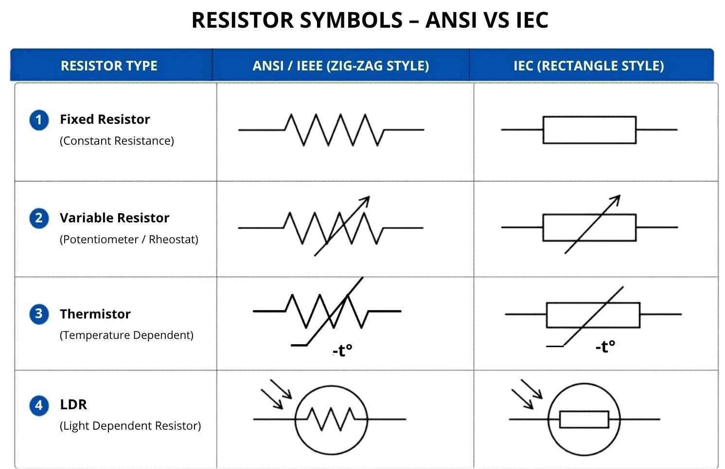
Different types of resistor symbols are used to represent how resistance behaves in a circuit under different conditions. The main types of resistor symbols include fixed, variable, temperature-dependent, and light-dependent resistors. The most common resistor symbols used in circuit diagrams are shown below for quick reference.
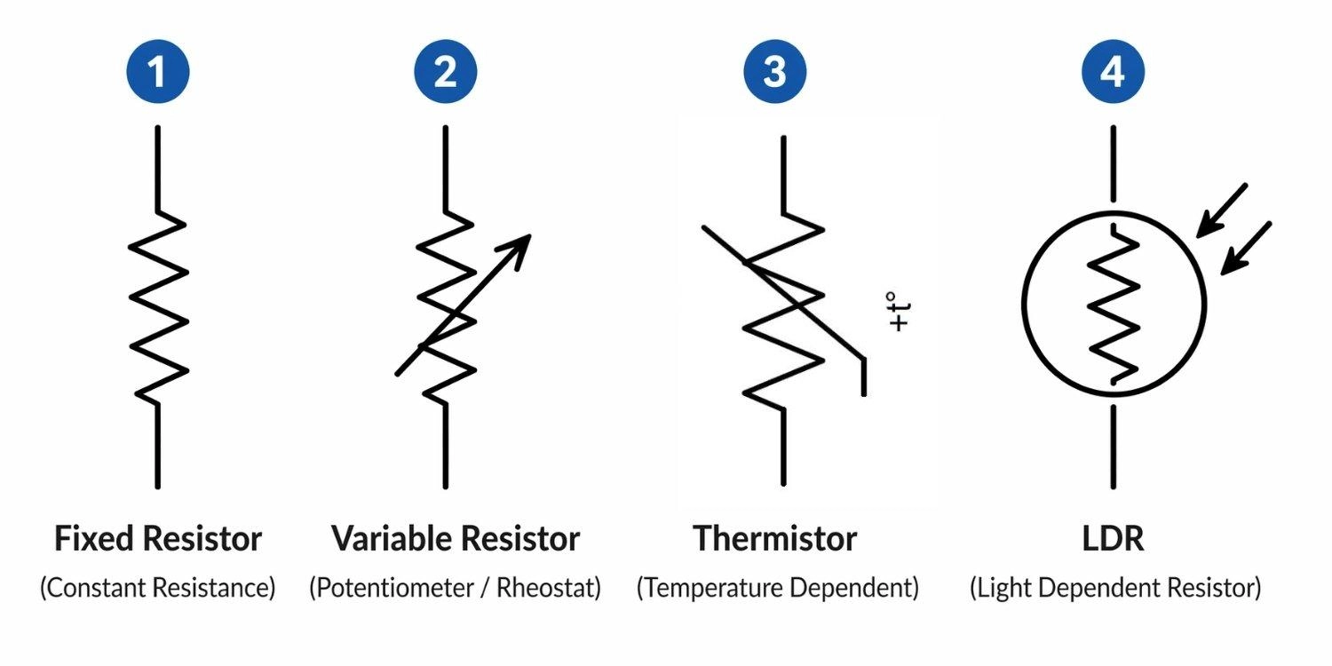
Fixed Resistor Symbol
Constant resistance, no adjustment. This is a standard resistor with a set value that never changes. It represents a linear, passive component with a static ohmic value. The schematic symbol remains identical regardless of whether it is a high-wattage wirewound resistor or a microscopic SMD component.
Tip: To identify the physical parts later, refer to the SMD resistor code guide.
Variable Resistor Symbol
Adjustable resistance via manual control. This is a general symbol for a resistor you can adjust manually, like a volume knob. It is typically indicated by an arrow crossing the base symbol.
- Potentiometer Symbol: Three-terminal voltage divider. A potentiometer acts as an adjustable voltage divider. Its symbol features an arrow pointing directly to the center of the resistor body.
- Rheostat Symbol: Two-terminal current limiter. A rheostat (two terminals) acts as a variable current limiter. Its symbol is usually drawn with an arrow striking diagonally across the resistor.
Thermistor Symbol (NTC vs PTC)
Automatic resistance shifts based on temperature. This is a resistor that reacts automatically to heat. Characterized by a diagonal intersecting line, its resistance shifts non-linearly with thermal changes. An NTC (Negative Temperature Coefficient) drops in resistance as heat rises; a PTC (Positive Temperature Coefficient) increases resistance to protect against overcurrent faults.
Light-Dependent Resistor (LDR) Symbol
Resistance changes based on light exposure. This is a resistor that changes value based on light exposure. Drawn with inward-pointing arrows representing incoming photons, it exhibits photoconductive behavior, drastically decreasing its electrical impedance as ambient lux levels increase.
Types of Resistor Symbol Summary Table
Here’s a quick reference table:
| Symbol Type | Simple Function | Technical Characteristic |
|---|---|---|
| Fixed | Constant resistance | Static ohmic value, linear dissipation |
| Variable | Adjustable via knob | Adjustable voltage divpider / current limiter |
| Thermistor | Reacts to temperature | Non-linear thermal coefficient (NTC/PTC) |
| LDR | Reacts to light | Photoconductive impedance shift |
What Is the Resistor Symbol?
A resistor symbol is a graphical representation used in circuit diagrams to show a component that limits current. It appears as a zig-zag (ANSI) or rectangle (IEC).
It’s a standard drawing used in circuit diagrams so engineers don't have to sketch realistic 3D pictures of physical components. It acts as a logical placeholder in Electronic Design Automation (EDA) tools, helping represent how current flows without drawing physical parts.
Purpose of Resistor Schematic Symbol in Circuit Diagram
Resistor symbols make circuits easier to read and design. They replace real components with simple visuals so engineers can quickly understand connections.
In design tools, these symbols also help generate netlists and support simulation (SPICE), allowing accurate circuit analysis based on Ohm’s Law (V = I/R).
Where Is the Resistor Symbol Used? (Circuit Schematics & PCB Design)
You’ll see them right away in blueprint-style circuit diagrams. They are primarily used in schematic capture editors (like EasyEDA, KiCad, Altium, or Eagle). The symbol serves as the logical schematic entity that will later be mapped to a physical copper footprint (such as an 0603 or 0805 SMD package) during the layout phase.
ANSI vs IEC Resistor Symbol
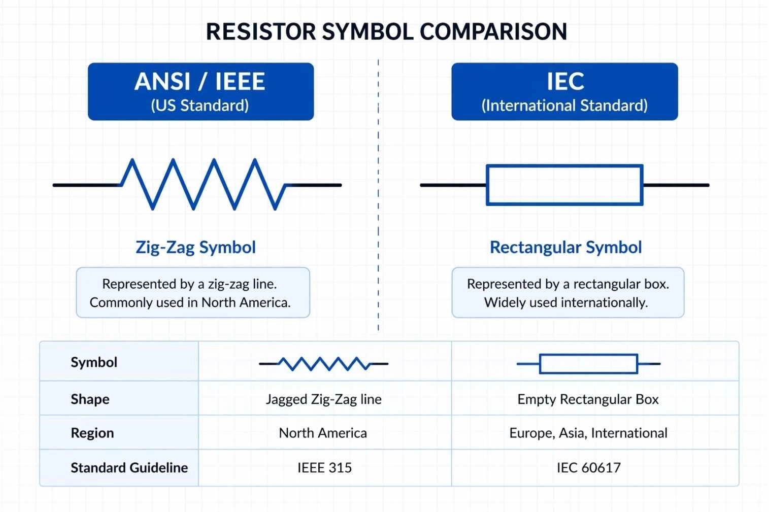
Figure: Comparison of the ANSI zig-zag resistor symbol and the IEC rectangular box resistor symbol.
ANSI Resistor Symbol (Zigzag Line)
This symbol is drawn as a jagged, zig-zag line. It is the IEEE 315 standard adopted primarily in the United States and North America. It historically represents a coiled length of resistive wire.
IEC Resistor Symbol (Rectangle)
This symbol is drawn as a simple, empty rectangular box. It is the IEC 60617 international standard used predominantly in Europe, Asia, and most modern global EDA software libraries.
Key Differences and Standards of ANSI vs IEC
They look different but do exactly the same thing. The visual difference stems from distinct global standardizing bodies. However, in any modern EDA tool, an ANSI symbol and an IEC symbol generate the exact same electrical netlist data.
ANSI vs IEC Resistor Symbol Comparison Table
| Feature | ANSI / IEEE Standard | IEC Standard |
|---|---|---|
| Shape | Jagged Zig-Zag line | Empty Rectangular Box |
| Region | North America | Europe, Asia, International |
| Standard Guideline | IEEE 315 | IEC 60617 |
Resistor Symbol in Circuit Diagram
In circuit diagrams, resistor symbols are used to show how components control current and voltage in a system.
Component Labels of Resistor Symbol (R1, R2, etc.)
This is the name tag for the part on the drawing. Known as a reference designator, this alphanumeric code uniquely identifies the specific component instance, linking the schematic symbol directly to the Bill of Materials (BOM) and pick-and-place files.
Value Representation of Resistor (Ω, kΩ, MΩ)
This indicates how much resistance the part has and determines the impedance multiplier. You will often see European notation in which the multiplier replaces the decimal point (e.g., 4k7 instead of 4.7kΩ) to prevent print errors when reading schematics.
How to Read a Resistor Symbol in a Circuit
Reading a resistor symbol correctly is essential for understanding how a circuit works.
Follow these quick steps:
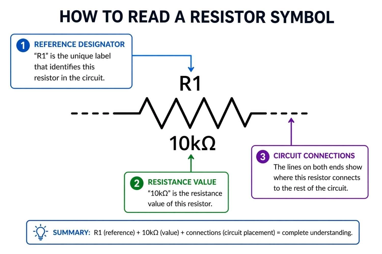
Figure: How to read resistor symbol labeled R1 value diagram in a circuit schematic
Step 1: Identify Resistor Symbol Type (ANSI vs IEC)
Start by looking at the shape to see if it is a box or a zig-zag. From there, identify the base standard and note any modifying lines (like arrows or circles) to determine if it is a passive linear device, a variable resistor, or an environmental sensor.
Step 2: Read Labels and Resistance Value
Find the component's name and its strength. Locate the reference designator (e.g., R15) and its ohmic value (e.g., 10k). This tells you exactly what part to source during procurement.
Step 3: Understand Resistor Circuit Position
Where a resistor is placed changes what it does. Trace the netlist; if placed in series, it acts as a current limiter. If placed in parallel to ground or VCC, it acts as a pull-down or pull-up resistor to stabilize digital logic gates.
Real Circuit Examples Using Resistor Symbols
Resistors are frequently used to dim lights or split power.
LED Circuit Example
- Limits current
- Prevents LED damage
- Explanation: Placed in series, the resistor limits forward current to prevent thermal runaway in the LED.
Voltage Divider Circuit Example
- Splits voltage
- Provides stable output
- Explanation: Two resistors placed in series between a source and ground. The center junction provides a precise, stepped-down fraction of the input voltage.
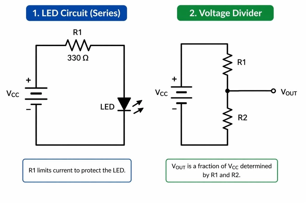
Figure: Schematic representation of an LED circuit utilizing a resistor symbol and a voltage divider network featuring a dual resistor symbol configuration.
Resistor Symbol vs Other Circuit Symbols
Resistor vs Capacitor Symbol
Resistors slow down power, while capacitors hold power like tiny batteries. A resistor turns electrical energy into heat (active power). A capacitor symbol (two parallel lines) represents a reactive component that stores energy in an electrostatic field.
See our capacitor symbol explained guide for visual comparisons.
Resistor vs Inductor Symbol
Inductors are wire coils used for filtering signals. While both impede AC signals, they do so differently (inductive reactance vs. resistive impedance). The inductor symbol is drawn as a series of curved loops, distinctly different from the sharp points of the ANSI resistor zig-zag.
Passive Component Symbol Cheat Sheet
| Component | Symbol Visual | Simple Function | Technical Function |
|---|---|---|---|
| Resistor | Zig-zag or Box | Limits current | Dissipates real power as heat |
| Capacitor | Parallel plates | Stores energy | Reactive electrostatic storage |
| Inductor | Coiled loops | Filters AC | Reactive magnetic storage |
Resistor Symbol in PCB Design and Schematics
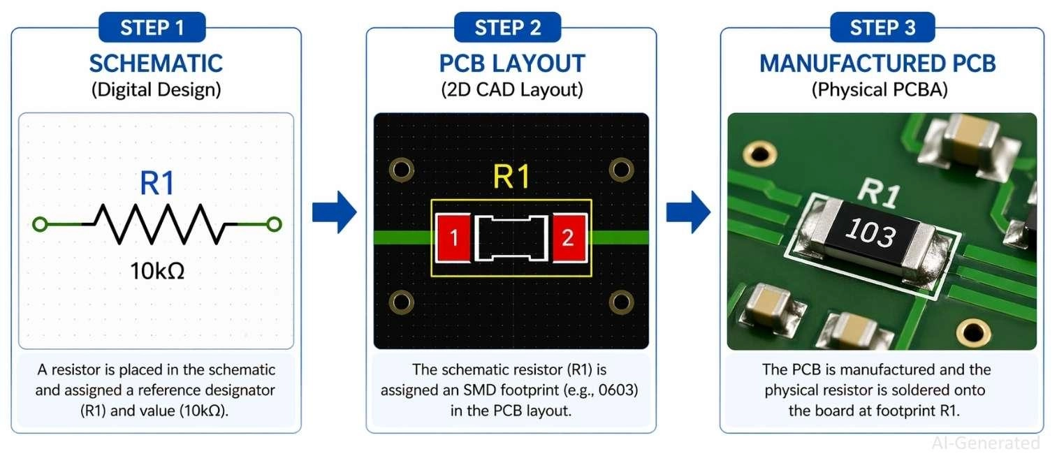
Figure: Showing a digital schematic resistor symbol converted to a PCB layout footprint and finally a manufactured PCBA component.
Circuit Schematics to PCB Workflow
The digital drawing connects to software that tells the factory how to wire the physical board. Completing your schematic generates a netlist. This maps the logical pins of your resistor symbols to specific X/Y copper coordinates in the PCB layout editor.
Assigning Footprints to Resistors
You have to tell the software what physical size the actual part is. Before layout, your symbol must be assigned a 2D physical footprint. Engineers choose sizes based on power dissipation limits and the surface mount vs through-hole debate.
You can easily find physically available footprints to match your symbols on the JLCPCB Parts Library.
PCB Manufacturing with JLCPCB
Once your design is finalized, upload your files to JLCPCB for fabrication and assembly. Generate and submit your Gerber files for PCB fabrication, and provide your BOM and CPL files for PCB assembly and component placement.
To reduce manual soldering and improve production efficiency, JLCPCB’s PCB Assembly service uses automated SMT equipment to place components with high precision and consistency across your design.
FAQs about Resistor Symbol
Q: Why do resistor symbols look different in circuit diagrams?
Different standards (ANSI and IEC) use different shapes, but both represent the same electrical function.
Q: How do you draw a resistor symbol in a circuit diagram?
Draw a zig-zag line (ANSI) or a rectangle (IEC) between two connection points.
Q: What does a variable resistor symbol indicate?
It shows adjustable resistance, typically marked with an arrow across the resistor symbol.
Q: Can resistor symbols show power rating or tolerance?
No, these values are not part of the symbol, they are defined in specifications or the BOM.
Q: What happens if you misread a resistor symbol in a circuit?
It can cause incorrect current flow, circuit malfunction, or even component damage.
Conclusion
Understanding resistor symbols in circuit diagrams is the easiest and most important step to turning your idea into a working circuit. Whether analyzing an ANSI zig-zag or an IEC rectangle, mastering reference designators, ohmic values, and symbol variants ensures your schematic capture is structurally sound. This accuracy guarantees a seamless netlist export, allowing you to assign exact physical footprints and reliably manufacture professional-grade circuit boards.
Popular Articles
• How to Create a Bluetooth-Controlled Car With Arduino: A Step-by-Step Guide
• How to Design and Assemble a Reliable ESP32 Module PCB on a 2-Layer Board
• The Ultimate Guide to Relay Symbol: Coil, Contacts, Diagrams, and Circuit Applications
• How to Identify SMD LED Polarity: Markings, Testing, and PCB Tips
• The Ultimate Guide to PCBA: Process,Types and Techniques for the Electronics Enthusiast
Keep Learning
How to Design an ESP32-S3 Development Board from Scratch: A 4-Layer PCB Design Tutorial
Designing your own ESP32-S3 development board gives you complete control over your hardware architecture while preparing your IoT projects for commercial production. Instead of relying on bulkier, off-the-shelf boards, building a custom design allows you to optimize the board space, expose only the required GPIO pins, and integrate peripherals directly onto a single substrate. In this tutorial, we will design a 4-layer ESP32-S3 development board from scratch. We will walk through the entire hardware d......
Arduino LED Driver Tutorial: Control More LEDs with 74HC595 and MAX7219
Arduino GPIO pins run out quickly in larger LED projects. By utilizing dedicated LED drivers and expansion ICs, you can drastically reduce pin usage, eliminate processor-heavy multiplexing loops, and simplify display wiring. In this guide, you will learn the operational architecture, wiring configurations, cascading techniques, and optimization strategies for the 74HC595 shift register and the MAX7219 LED driver. Why Arduino Projects Need LED Driver ICs Arduino GPIO and Current Limitations An ATmega32......
How to Create a Bluetooth-Controlled Car With Arduino: A Step-by-Step Guide
This tutorial walks through the complete engineering and implementation of a two-wheel Bluetooth RC car with an Arduino Nano module on a specially designed PCBA (Printed Circuit Board Assembly). While many hobbyists start by wiring motors and Bluetooth modules with jumper cables on a breadboard, this approach is prone to disconnection and signal noise. This guide upgrades that process by teaching you how to design a professional mainboard. Key Design Features Controller: Arduino Nano used as a plug-in......
Fiducial Marks in PCB and SMT Assembly: A Complete Guide to Accuracy and Design Rules
Modern Printed Circuit Boards (PCBs) are complex, integrating high-density components like 0.4mm pitch Ball Grid Arrays (BGAs), 0201 passives, and fine-pitch Quad Flat No-Lead (QFN) packages. In this advanced manufacturing environment, achieving placement accuracy measured in micrometers is crucial. A significant challenge in automated manufacturing is how pick-and-place machines, which handle thousands of components per hour, precisely locate the PCB. A board on a conveyor system is never in the perf......
Alternating Current vs Direct Current (AC vs DC): What's the Difference?
Electric current flows in two primary forms: alternating current (AC) and direct current (DC). AC periodically reverses direction, while DC flows steadily in one direction. AC powers the industrial and residential electrical grids, while DC powers batteries, electric vehicles, and nearly all modern consumer electronics. Understanding the core differences between AC and DC matters when designing power supplies, selecting electronic components, or laying out printed circuit boards (PCBs). This guide com......
Arduino LED Multiplexing Tutorial: Control More LEDs with Fewer Pins
The Arduino Uno is a powerful tool for prototyping, but driving multiple LEDs directly quickly exhausts its 20 GPIO pins and its 200 mA absolute maximum package current limit. To bypass these hardware bottlenecks, engineers and hobbyists use LED multiplexing to scale display outputs efficiently without upgrading the microcontroller. In this guide, you will learn the core principles of LED matrix scanning, Charlieplexing, refresh timing, ghosting fixes, and practical Arduino code without relying on any......