
Diode Voltage Drop: Values, Formula, and How to Measure It
11 min
- What Is Diode Voltage Drop?
- Diode Voltage Drop Chart by Diode Type
- Common Mistakes about Diode Voltage Drop
- Why Do Diodes Have a Voltage Drop?
- Factors Affecting Diode Voltage Drop
- How to Calculate Diode Voltage Drop
- How to Measure Diode Voltage Drop With a Multimeter
- Why Diode Voltage Drop Matters in Circuit Design
- FAQs about Diode Voltage Drop
- Conclusion
Every diode loses some voltage when it conducts. That loss is the diode voltage drop, and it decides how much voltage reaches your load, how much heat your part makes, and whether your low-voltage rail still works.
This guide covers typical forward voltage by type, the formula behind it, what changes it, how to measure it with a multimeter, and why it matters in real circuits.
What Is Diode Voltage Drop?
Diode voltage drop is the forward voltage (Vf) that appears across a diode when current flows from anode to cathode. It is also called forward voltage drop or forward voltage (Vf).
Forward voltage (Vf) is the voltage measured across a diode while it conducts in forward bias. Current enters the anode and exits the cathode. As the diode conducts, a forward voltage develops across the junction. The exact value depends on current, temperature, and diode construction.
An ideal diode drops 0V and acts as a perfect switch. A real diode always loses some voltage because its semiconductor junction needs a minimum potential to conduct. That lost voltage turns into heat and never reaches the load. When designing a circuit board, checking the standard diode symbol and orientation ensures that forward-bias conditions are properly established.
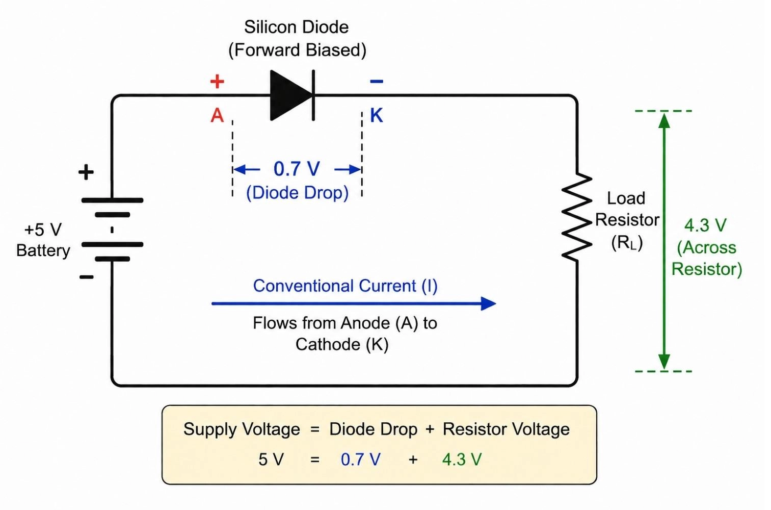
Figure: Forward-biased diode connected to a battery and resistor showing a 0.7V voltage drop across the diode and the remaining voltage across the load resistor.
Diode Voltage Drop Chart by Diode Type
Forward voltage depends on the semiconductor material and, for LEDs, on the emitted color. Use this chart as a quick reference, then confirm against the part datasheet.
| Diode Type | Typical Forward Voltage |
|---|---|
| Germanium | 0.25 - 0.3V |
| Schottky | 0.15 - 0.45V |
| Silicon PN | 0.6 - 0.8V |
| Power Rectifier | 0.8 - 1.2V |
| Red LED | 1.8 - 2.2V |
| Green LED | 2.0 - 3.2V |
| Blue LED | 2.8 - 3.8V |
| White LED | 3.0 - 3.6V |
Common Mistakes about Diode Voltage Drop
- Assuming every diode drops 0.7V
- Ignoring temperature effects
- Using LED forward voltage as a fixed value
- Designing from typical values instead of datasheet values
#1 Voltage Drop of Silicon Diode
Silicon is the default. Most silicon diodes operate around 0.6–0.8V. Engineers round this to a 0.7V drop, with power rectifiers running higher at their rated current.
- 1N4148 (signal): ~0.7V
- 1N4007 (rectifier): up to ~1.1V at 1A
#2 Schottky Diode Voltage Drop
A Schottky diode uses a metal-semiconductor junction instead of a PN junction. Result: lower forward voltage, higher efficiency, faster switching. Tradeoff: higher reverse leakage current.
Example devices: 1N5817, 1N5819, SS14 (all readily sourced via the Parts Product Page on JLCPCB). Forward voltage typically 0.15-0.45V.
#3 Germanium Diode Voltage Drop
Germanium drops around 0.3V. Used for signal detection and classic crystal radio circuits. Example: 1N34A.
#4 Voltage Drop of LED
An LED is a diode that drops far more voltage than silicon, and the value tracks the color. Refer to the chart above for typical LED forward voltages, from red near 2V to white near 3.3V.
#5 Voltage Drop of Zener Diode
In forward mode, a Zener behaves like a normal silicon diode, around 0.7V. Its purpose is reverse mode, where it conducts at a fixed breakdown voltage (Vz). Do not confuse forward Vf with the reverse Vz rating. Just like choosing between a BJT vs MOSFET, picking the right operating mode depends on your power and switching needs.
#6 Voltage Drop of Fast Recovery Diode
These diodes carry forward voltage similar to standard silicon but are optimized for switching speed, which makes them common in switch-mode power supplies and high-frequency rectifiers.
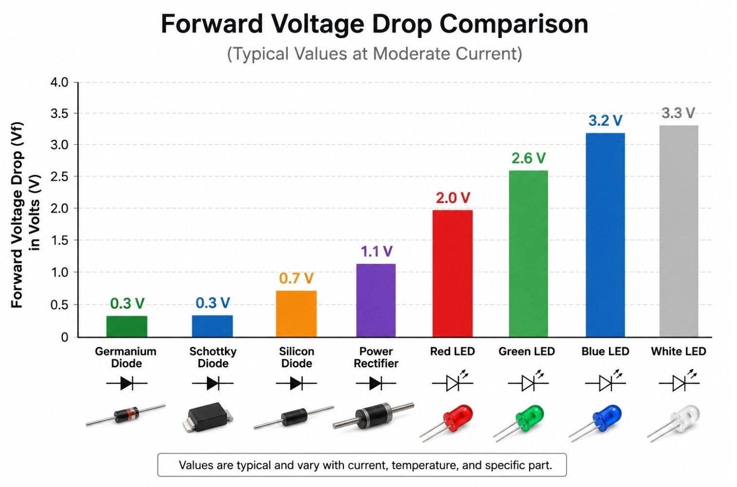
Figure: Comparing germanium, Schottky, silicon, rectifier, and LED forward voltage drops.
Why Do Diodes Have a Voltage Drop?
The PN Junction Barrier
Where P-type and N-type silicon meet, charges diffuse and leave a depletion region with a built-in electric field. That field is a potential barrier. Current cannot flow until the applied voltage overcomes it.
Why Silicon Is Called a 0.7V Diode
0.7V is the voltage that overcomes a silicon junction barrier under typical conditions. It is an engineering shortcut, not a fixed constant. Real Vf depends on current and temperature.
Why Diode Forward Voltage(Vf) Is Not Fixed
The diode I-V curve is exponential, not an abrupt switch. Small current flows below 0.7V, and there is no hard on/off threshold. Vf also shifts with current, covered in the next section.
Factors Affecting Diode Voltage Drop
#1 Diode Current
More forward current means higher Vf. The rise is gradual because the relationship is logarithmic, but it is real: a diode at 5A drops more than the same diode at 5mA.
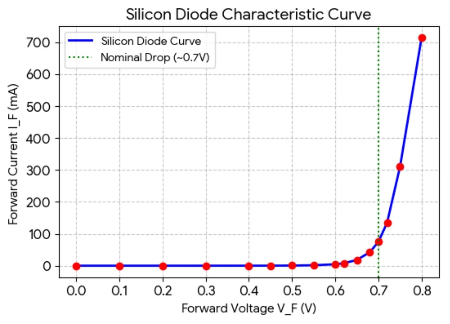
Figure: Silicon Diode I-V curve showing increasing forward voltage as current increases.
#2 Diode Temperature
Silicon Vf falls roughly -2mV/°C. A hotter diode drops less voltage. This matters for thermal stability: as a diode heats up, its Vf falls, letting more current through, which heats it further. In high-current circuits, this effect can contribute to thermal runaway if current is not properly limited.
Ensuring proper thermal profiles during the reflow soldering process is vital to protect sensitive PN junctions from excessive heat damage.
#3 Semiconductor Material
- Silicon: ~0.7V
- Germanium: ~0.3V
- Schottky: 0.15–0.45V
#4 Device Structure
- Signal diodes: small junctions, modest current
- Power rectifiers: larger junctions, run at high current
- High-current devices: Vf rises under full load
Larger power rectifiers often exhibit higher forward voltage at their rated current because of higher operating current levels and device construction.
How to Calculate Diode Voltage Drop
Method 1: Quick Engineering Approximation
For fast hand calculations, assume a fixed drop and subtract it from the supply.
| Type | Approximation |
|---|---|
| Silicon | 0.7V |
| Schottky | 0.3V |
| Germanium | 0.3V |
| LED | Datasheet value |
Example: a 5V rail through a silicon diode leaves 5V - 0.7V = 4.3V for the load.
Method 2: Using the Shockley Diode Equation
For exact behavior, use the Shockley diode equation:
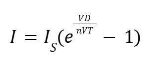
- Is: reverse saturation current
- n: ideality factor, 1 to 2 for real diodes
- VT: thermal voltage, ≈25.85mV at 25°C
- VD: voltage across the diode
The equation shows current rising exponentially with voltage. For most design work, the fixed approximation or the datasheet curve is enough.
Method 3: Using Diode Datasheet Curves
The most accurate value comes from the part datasheet.
- Identify the diode
- Find its datasheet
- Locate the Vf vs If graph
- Read Vf at your operating current
- Adjust for temperature
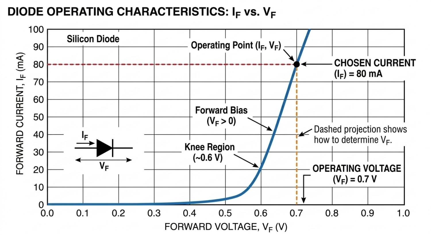
Figure: Diode Datasheet forward-current versus forward-voltage graph showing how to determine operating Vf.
Case Study: 1N4007 vs. 1N5819 Datasheet Values
Real parts give concrete numbers instead of round approximations:
- 1N4007: Vf = 1.1V at If = 1A
- 1N5819: Vf ≈ 0.45V at If = 1A
Forward-voltage specifications around 1.1V at 1A are common in 1N4007 datasheets. Same current, very different drop, because the 1N5819 is a Schottky.
How to Measure Diode Voltage Drop With a Multimeter
Warning
Power off the circuit and discharge capacitors before testing. For accurate in-circuit readings, isolate one diode lead.
- Turn the power off
- Discharge capacitors
- Set the meter to diode mode
- Connect the red probe to the anode
- Connect the black probe to the cathode
- Read displayed Vf
- Reverse probes to verify OL (open line)
Diode test mode applies a small test current, typically in the microamp to milliamp range, depending on the meter, so readings sit below the nominal 0.7V. A healthy diode reads a forward value one way and OL when reversed. The same reading in both directions means a shorted diode.
| Diode Type | Typical Reading |
|---|---|
| Silicon | 0.5–0.8V |
| Schottky | 0.15–0.45V |
| Germanium | 0.2–0.4V |
| LED | 1.5–3.5V |
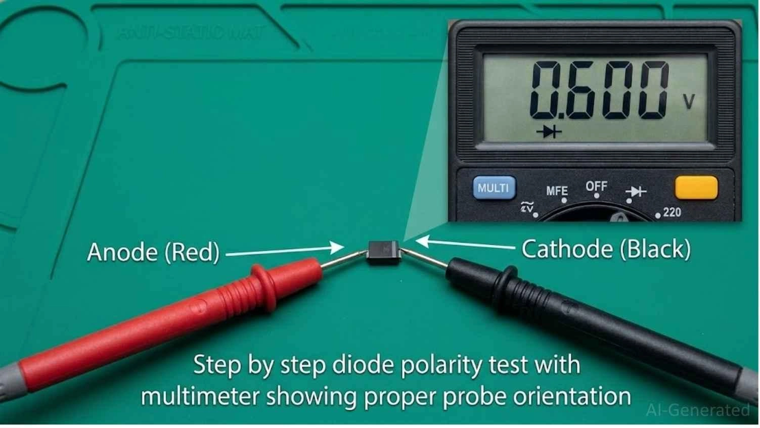
Figure: Digital multimeter in diode test mode measuring a silicon diode with probes connected in forward bias.
Why Diode Voltage Drop Matters in Circuit Design
Power Dissipation of Diode
Every conducting diode burns power as heat:
P = Vf * If
| Current | 0.7V Diode Loss |
|---|---|
| 100mA | 70mW |
| 1A | 0.7W |
| 5A | 3.5W |
At higher currents, heat forces a heatsink or a lower-Vf part.
Rectifier Diode Efficiency
- Half-wave: one diode drop
- Full-wave (center-tap): one drop in the path
- Bridge: two drops in the conducting path
A bridge rectifier typically introduces two diode drops in the conducting path, which hurts efficiency on low-voltage supplies.
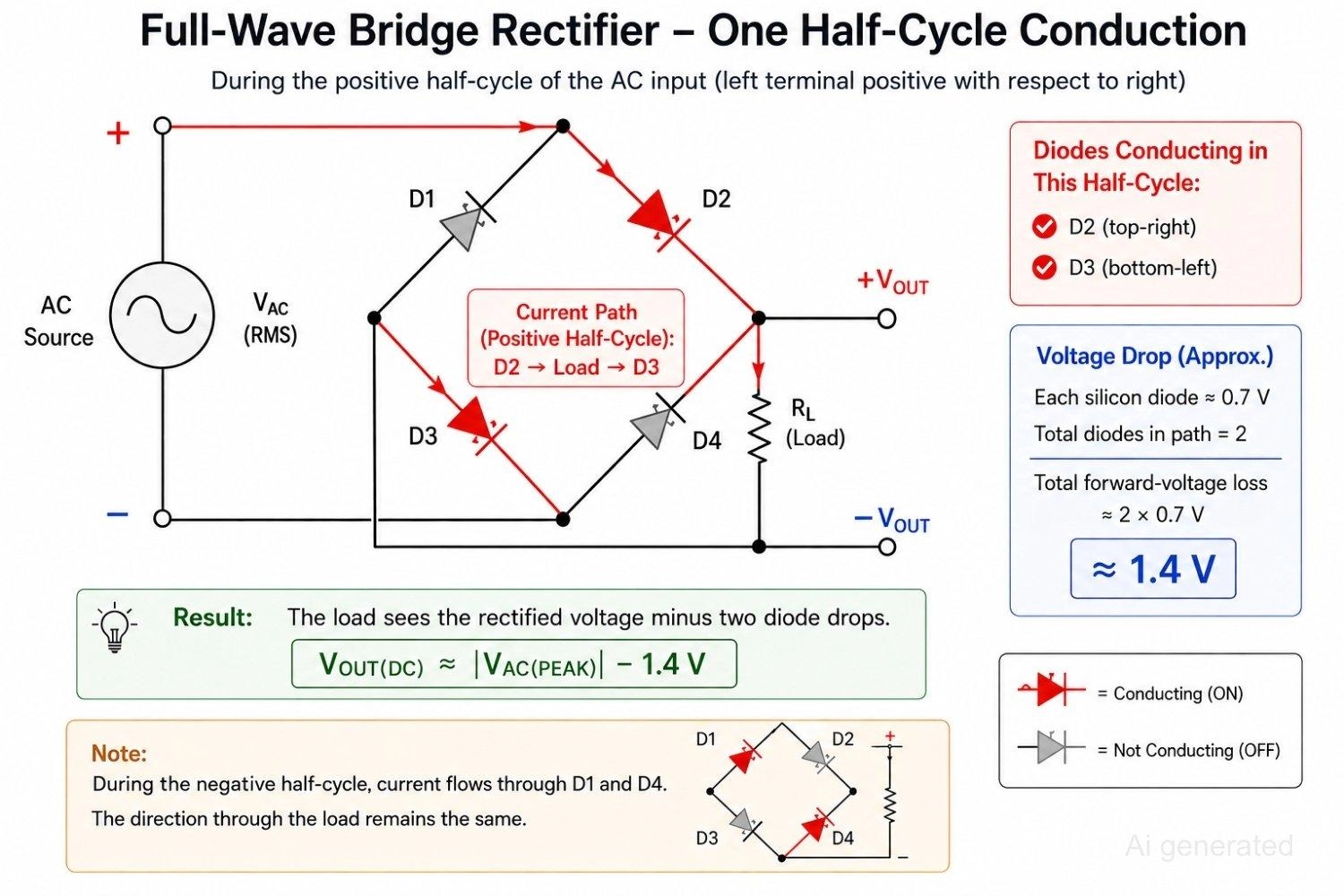
Figure: Bridge rectifier circuit showing current flowing through two conducting diodes and resulting forward-voltage loss.
Diode Voltage Drop in Reverse Polarity Protection
Lower drop means less wasted voltage and heat in the protection path.
| Method | Voltage Loss |
|---|---|
| Silicon Diode | High |
| Schottky Diode | Lower |
| Ideal Diode MOSFET | Minimal |
Note
Picking a low-Vf Schottky from a verified assembly parts library, such as the one from JLCPCB Parts Library, keeps the protection loss small.
Diode in Low-Voltage Electronics
Diode drop hurts most where the supply is small:
- 3.3V systems
- Battery-powered devices
- IoT nodes
- USB-powered circuits
On a 3.3V rail, a 0.7V silicon drop wastes over a fifth of the supply. A Schottky or ideal-diode MOSFET recovers most of it. Making these selections during early-stage PCBA vs PCB design considerations prevents voltage sag and layout issues down the road.
FAQs about Diode Voltage Drop
Q: What is the voltage drop across a diode?
The forward voltage drop (Vf) is the amount of electrical potential lost when current travels from anode to cathode. It typically ranges from 0.6V to 0.8V for silicon PN diodes and is much lower (0.15V to 0.45V) for Schottky devices.
Q: Why is a silicon diode voltage drop about 0.7V?
The 0.7V threshold is a standard engineering approximation representing the potential barrier of the PN junction depletion region. Under real-world operation, this value changes dynamically based on the operating current and temperature.
Q: What is the voltage drop of a Schottky diode?
Schottky diodes typically drop between 0.15V and 0.45V. Because they utilize a metal-semiconductor junction rather than a traditional PN junction, they achieve higher power efficiency and faster switching.
Q: What is the voltage drop of an LED?
A light-emitting diode's drop correlates directly to its color: red LEDs hover around 1.8V to 2.2V, while green, blue, and white LEDs require up to 3.0V to 3.8V to fully conduct.
Q: How do you calculate the voltage drop across a diode?
For rapid estimations, use standard values like 0.7V for silicon or 0.3V for Schottky. For precise engineering calculations, consult the datasheet for the forward current versus forward voltage curve or apply the Shockley diode equation.
Q: Does diode voltage drop increase with current?
Yes, Vf rises gradually as current increases. This non-linear relationship is logarithmic, meaning higher currents yield greater forward voltage losses across the semiconductor junction.
Q: Does temperature affect diode forward voltage?
Yes. Silicon has a negative thermal coefficient of approximately -2mV/°C. As the junction heats up, the potential barrier decreases, causing the forward voltage drop to fall.
Q: How do you measure diode voltage drop with a multimeter?
Power down the circuit, discharge capacitors, set your meter to the diode setting, and place the red probe on the anode and black on the cathode to read the active Vf. Reverse the probes to confirm OL (open line).
Q: What is the voltage drop across a bridge rectifier?
A full-wave bridge rectifier introduces two diode drops in series within the active current path. For standard silicon diodes, this results in a cumulative voltage loss of roughly 1.4V.
Conclusion
Diode voltage drop is the forward voltage a diode loses while conducting, and it varies by technology: silicon near 0.7V, Schottky much lower, LEDs much higher. Current, temperature, and device construction all shift the value, so datasheet curves give the most accurate figure. Measuring Vf with a multimeter in diode mode is a fast, reliable check for troubleshooting and part selection.
Popular Articles
• How to Create a Bluetooth-Controlled Car With Arduino: A Step-by-Step Guide
• How to Design and Assemble a Reliable ESP32 Module PCB on a 2-Layer Board
• The Ultimate Guide to Relay Symbol: Coil, Contacts, Diagrams, and Circuit Applications
• How to Identify SMD LED Polarity: Markings, Testing, and PCB Tips
• The Ultimate Guide to PCBA: Process,Types and Techniques for the Electronics Enthusiast
Keep Learning
How to Design an ESP32-S3 Development Board from Scratch: A 4-Layer PCB Design Tutorial
Designing your own ESP32-S3 development board gives you complete control over your hardware architecture while preparing your IoT projects for commercial production. Instead of relying on bulkier, off-the-shelf boards, building a custom design allows you to optimize the board space, expose only the required GPIO pins, and integrate peripherals directly onto a single substrate. In this tutorial, we will design a 4-layer ESP32-S3 development board from scratch. We will walk through the entire hardware d......
Arduino LED Driver Tutorial: Control More LEDs with 74HC595 and MAX7219
Arduino GPIO pins run out quickly in larger LED projects. By utilizing dedicated LED drivers and expansion ICs, you can drastically reduce pin usage, eliminate processor-heavy multiplexing loops, and simplify display wiring. In this guide, you will learn the operational architecture, wiring configurations, cascading techniques, and optimization strategies for the 74HC595 shift register and the MAX7219 LED driver. Why Arduino Projects Need LED Driver ICs Arduino GPIO and Current Limitations An ATmega32......
How to Create a Bluetooth-Controlled Car With Arduino: A Step-by-Step Guide
This tutorial walks through the complete engineering and implementation of a two-wheel Bluetooth RC car with an Arduino Nano module on a specially designed PCBA (Printed Circuit Board Assembly). While many hobbyists start by wiring motors and Bluetooth modules with jumper cables on a breadboard, this approach is prone to disconnection and signal noise. This guide upgrades that process by teaching you how to design a professional mainboard. Key Design Features Controller: Arduino Nano used as a plug-in......
Fiducial Marks in PCB and SMT Assembly: A Complete Guide to Accuracy and Design Rules
Modern Printed Circuit Boards (PCBs) are complex, integrating high-density components like 0.4mm pitch Ball Grid Arrays (BGAs), 0201 passives, and fine-pitch Quad Flat No-Lead (QFN) packages. In this advanced manufacturing environment, achieving placement accuracy measured in micrometers is crucial. A significant challenge in automated manufacturing is how pick-and-place machines, which handle thousands of components per hour, precisely locate the PCB. A board on a conveyor system is never in the perf......
Alternating Current vs Direct Current (AC vs DC): What's the Difference?
Electric current flows in two primary forms: alternating current (AC) and direct current (DC). AC periodically reverses direction, while DC flows steadily in one direction. AC powers the industrial and residential electrical grids, while DC powers batteries, electric vehicles, and nearly all modern consumer electronics. Understanding the core differences between AC and DC matters when designing power supplies, selecting electronic components, or laying out printed circuit boards (PCBs). This guide com......
Arduino LED Multiplexing Tutorial: Control More LEDs with Fewer Pins
The Arduino Uno is a powerful tool for prototyping, but driving multiple LEDs directly quickly exhausts its 20 GPIO pins and its 200 mA absolute maximum package current limit. To bypass these hardware bottlenecks, engineers and hobbyists use LED multiplexing to scale display outputs efficiently without upgrading the microcontroller. In this guide, you will learn the core principles of LED matrix scanning, Charlieplexing, refresh timing, ghosting fixes, and practical Arduino code without relying on any......