
How to Read Resistor Color Code: Complete Guide with Chart and Examples
6 min
- 4-Band Resistor Color Code Explained
- 5-Band Resistor Color Code Explained
- 6-Band Resistor Color Code Explained
- Common Mistakes When Reading Resistor Color Codes
- FAQ
4-Band Resistor Color Code Explained
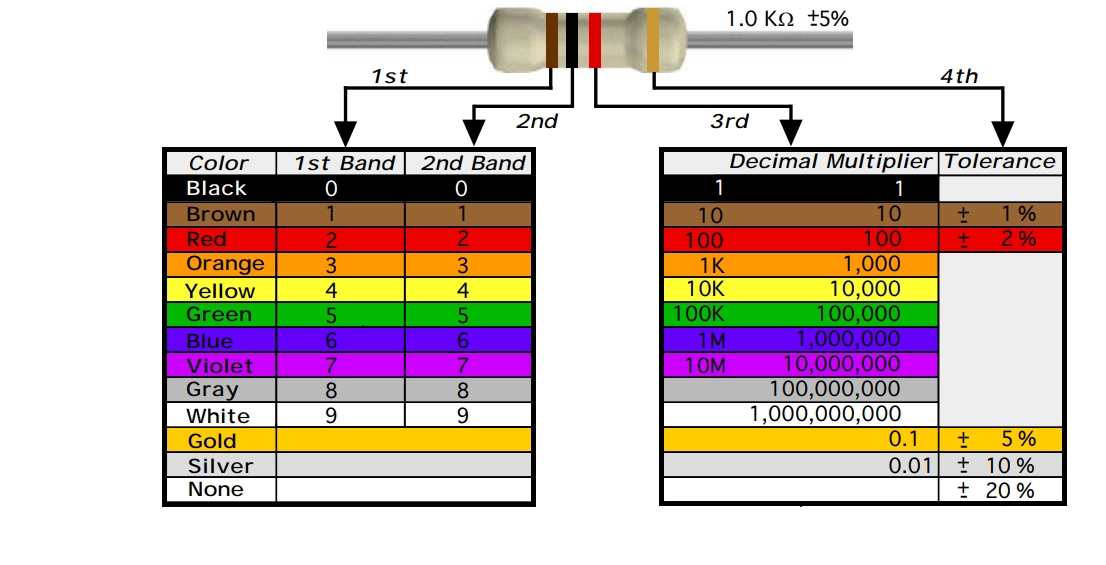
A 4-band resistor color code is one of the most common methods used to indicate resistance values in electronic components. It is widely used to help engineers and hobbyists quickly determine resistance values without using a resistor color code calculator.
In a standard 4-band resistor:
- First Band (Digit 1): Represents the first significant digit
- Second Band (Digit 2): Represents the second significant digit
- Third Band (Multiplier): Indicates the factor by which the first two digits are multiplied
- Fourth Band (Tolerance): Specifies the allowable deviation from the nominal resistance value
How to Read a 4-Band Resistor Color Code
Preparation: Hold the resistor so the band with the largest gap (or the gold/silver band) is on the right. Read from left to right.
- First & Second Bands (Digits): Match the colors to the chart to get the first two numbers.
- Third Band (Multiplier): This tells you how many zeros to add to the first two digits.
- Fourth Band (Tolerance): This represents the precision of the resistor (e.g., Gold = ±5%).
Example: 1kΩ Resistor (4-Band)
This is one of the most commonly used resistors, often found in pull-up circuits and basic LED applications.
- 1st Band: Brown (1)
- 2nd Band: Black (0)
- Multiplier: Red (×100)
- Tolerance: Gold (±5%)
Calculation:
10 × 100 = 1,000Ω (1kΩ)
5-Band Resistor Color Code Explained
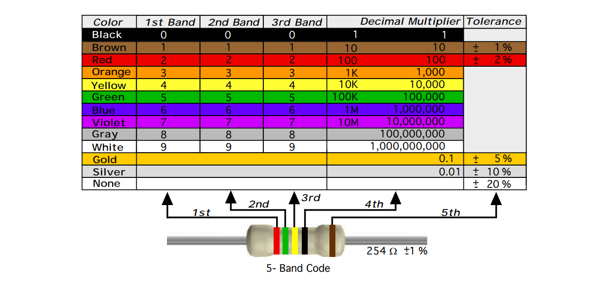
A 5-band resistor color code is typically used for high-precision resistors. Compared to a 4 band resistor color code, the 5-band version provides higher accuracy by including an additional significant digit.
In a standard 5-band resistor:
- First Band (Digit 1): First significant digit
- Second Band (Digit 2): Second significant digit
- Third Band (Digit 3): Third significant digit
- Fourth Band (Multiplier): Multiplies the three-digit value
- Fifth Band (Tolerance): Indicates the allowable deviation from the nominal resistance
How to Read a 5-Band Resistor Color Code
Preparation: To find the first band, look for the side where the color bands are closer together. The larger gap or the wider band should be on your right (this is the tolerance).
Follow these steps from left to right:
- First 3 Bands (Digits): Read the first three colors as the three significant digits of the resistance value.
- 4th Band (Multiplier): Multiply the first three digits by the value of this band (usually represented by the number of zeros).
- 5th Band (Tolerance): This band indicates the precision of the resistor (e.g., Brown = ±1%).
Example: 4.7kΩ Precision Resistor (5-Band)
- 1st Band: Yellow (4)
- 2nd Band: Violet (7)
- 3rd Band: Black (0)
- Multiplier: Brown (×10)
- Tolerance: Brown (±1%)
Calculation:
470 × 10 = 4,700Ω (4.7kΩ)
6-Band Resistor Color Code Explained
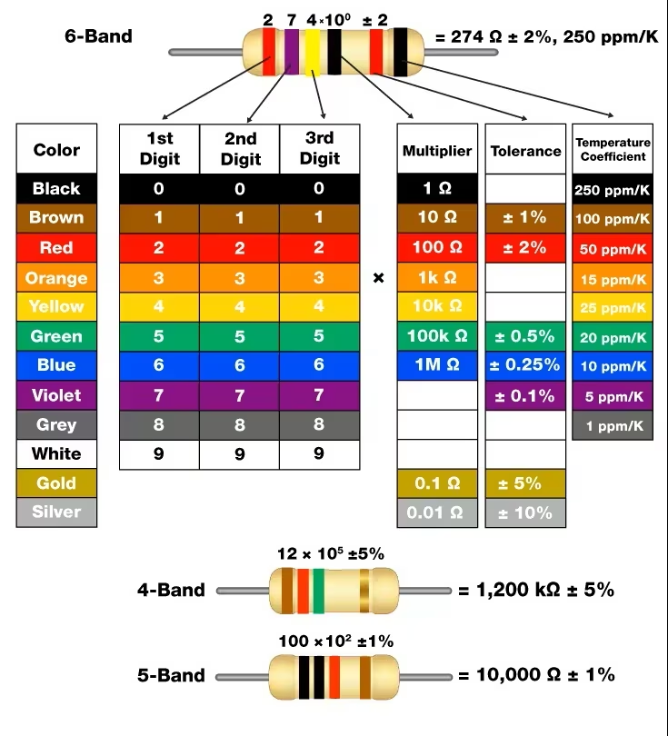
A 6 band resistor color code is used for high-precision resistors, adding an extra band to indicate the temperature coefficient, which describes how the resistance value changes with temperature.
In a standard 6-band resistor:
- First Band (Digit 1): First significant digit
- Second Band (Digit 2): Second significant digit
- Third Band (Digit 3): Third significant digit
- Fourth Band (Multiplier): Multiplies the three-digit value
- Fifth Band (Tolerance): Indicates the allowable deviation from the nominal resistance
- Sixth Band (Temperature Coefficient): Specifies how resistance changes with temperature (ppm/°C)
How to Read a 6-Band Resistor Color Code
Preparation:
To orient the resistor correctly, look for a larger gap between the 5th and 6th bands. This gap indicates that the 6th band is the Temperature Coefficient and should be on the right.
To read a 6-band resistor color code, follow these steps: (Read from Left to Right):
- First 3 Bands (Digits): Identify the first three colors to determine the three significant digits.
- 4th Band (Multiplier): Multiply the digits by this value (e.g., Orange = × 1,000).
- 5th Band (Tolerance): Indicates the precision (e.g., Brown = ±1%).
- 6th Band (Temperature Coefficient): Represents how much the resistance changes with temperature, expressed in ppm/°C (parts per million per degree Celsius).
Example: 10kΩ High-Precision Resistor (6-Band)
Common in temperature-sensitive and high-reliability applications such as medical and aerospace systems.
- 1st–3rd Bands: Brown (1), Black (0), Black (0) → 100
- Multiplier: Red (×100)
- Tolerance: Brown (±1%)
- Temp. Coefficient: Blue (10 ppm/°C)
Calculation:
100 × 100 = 10,000Ω (10kΩ)
Common Mistakes When Reading Resistor Color Codes
1. Reading the Resistor Backwards
One of the most frequent mistakes is starting from the wrong end.
Tip: Always identify the tolerance band first (gold/silver) and read from the opposite side.
2. Confusing Similar Colors
Colors like:
- Red vs Orange
- Brown vs Red
- Blue vs Violet
can look similar under poor lighting.
Tip: Use a reference chart or digital tool when in doubt.
3. Miscounting the Number of Bands
Confusing a 5-band resistor with a 4-band one can lead to 10× or 100× errors.
Tip: Always count carefully before decoding.
4. Ignoring the Multiplier Band
Some users correctly read the digits but forget to apply the multiplier.
Tip: This results in completely incorrect resistance values.
5. Assuming All Resistors Use Color Codes
Not all resistors use color bands.
- SMD resistors use numeric codes
- Zero-ohm resistors may not follow standard rules
Tip: Always identify the resistor type first.
6. Overlooking Tolerance
Tolerance affects circuit performance, especially in precision applications.
Tip: A 1kΩ resistor with ±5% tolerance can range from 950Ω to 1050Ω
FAQ
Q: What Is a "Reliability" Band on a Resistor?
In a 6-band resistor color code, the sixth band is known as the reliability band. It indicates the resistor’s failure rate, typically expressed as a percentage per 1,000 hours of operation. Not present in standard 4-band or 5-band resistors. This band is mainly used in high-reliability applications, such as aerospace, and industrial electronics, where long-term performance is critical. Rarely used in consumer electronics.
Q: How Do You Identify and Read SMD Resistor Codes?
SMD resistors (surface mount resistors) are typically small, black rectangular components without color bands. Instead of color coding, they use 3-digit, 4-digit, or alphanumeric markings to represent resistance values. Learn how to decode them step by step here: An Ultimate Guide to Read SMD Resistor Codes
Q: What Is a Zero-Ohm Resistor?
A zero-ohm resistor is a resistor with approximately 0Ω resistance, used primarily as a jumper or bridge on a PCB rather than for limiting current.
Although they are called “resistors,” their main function is to act as a low-cost, surface-mountable connection. Unlike standard resistors, zero-ohm resistors may use a single black band or be marked with “0” or “000” (in SMD form) and do not follow standard resistor color code rules. Zero-ohm resistors are commonly used for circuit routing and configuration, PCB design flexibility and automated assembly instead of wire jumpers.

- JLCPCB offers fast, high-quality PCB fabrication and assembly with a wide range of components—all in one place.
- Whether you're prototyping or scaling to production, get started with JLCPCB and bring your designs to life.
Popular Articles
• How to Identify SMD LED Polarity: Markings, Testing, and PCB Tips
• How to Create a Bluetooth-Controlled Car With Arduino: A Step-by-Step Guide
• How to Design and Assemble a Reliable ESP32 Module PCB on a 2-Layer Board
• The Ultimate Guide to Relay Symbol: Coil, Contacts, Diagrams, and Circuit Applications
• The Ultimate Guide to PCBA: Process,Types and Techniques for the Electronics Enthusiast
Keep Learning
How to Design an ESP32-S3 Development Board from Scratch: A 4-Layer PCB Design Tutorial
Designing your own ESP32-S3 development board gives you complete control over your hardware architecture while preparing your IoT projects for commercial production. Instead of relying on bulkier, off-the-shelf boards, building a custom design allows you to optimize the board space, expose only the required GPIO pins, and integrate peripherals directly onto a single substrate. In this tutorial, we will design a 4-layer ESP32-S3 development board from scratch. We will walk through the entire hardware d......
Circuit Breaker Symbols Explained: IEC, ANSI, MCB, and Pole Configuration Symbols
Electrical schematics are the universal language of power systems, control circuits, and printed circuit boards. Within these diagrams, the circuit breaker symbol is one of the most critical elements. Getting it right is essential for safety, troubleshooting, and manufacturing. An error as simple as mixing up a circuit breaker with a manual switch or an isolator can lead to catastrophic misinterpretations on the factory floor or during field maintenance. This guide provides a complete, technically acc......
How to Identify SMD LED Polarity: Markings, Testing, and PCB Tips
Surface-mount LED components are ubiquitous in electronics design, serving as everything from simple power indicators to complex lighting arrays. Unlike standard resistors, LEDs are polarized diodes. Identifying SMD LED polarity correctly is critical for prototype troubleshooting and high-volume PCB assembly. A reversed LED results in no light output, broken circuit paths, and potential diode breakdown if the reverse voltage exceeds the component's maximum rating (typically 5V or less for most indicat......
Arduino LED Driver Tutorial: Control More LEDs with 74HC595 and MAX7219
Arduino GPIO pins run out quickly in larger LED projects. By utilizing dedicated LED drivers and expansion ICs, you can drastically reduce pin usage, eliminate processor-heavy multiplexing loops, and simplify display wiring. In this guide, you will learn the operational architecture, wiring configurations, cascading techniques, and optimization strategies for the 74HC595 shift register and the MAX7219 LED driver. Why Arduino Projects Need LED Driver ICs Arduino GPIO and Current Limitations An ATmega32......
How to Create a Bluetooth-Controlled Car With Arduino: A Step-by-Step Guide
This tutorial walks through the complete engineering and implementation of a two-wheel Bluetooth RC car with an Arduino Nano module on a specially designed PCBA (Printed Circuit Board Assembly). While many hobbyists start by wiring motors and Bluetooth modules with jumper cables on a breadboard, this approach is prone to disconnection and signal noise. This guide upgrades that process by teaching you how to design a professional mainboard. Key Design Features Controller: Arduino Nano used as a plug-in......
Fiducial Marks in PCB and SMT Assembly: A Complete Guide to Accuracy and Design Rules
Modern Printed Circuit Boards (PCBs) are complex, integrating high-density components like 0.4mm pitch Ball Grid Arrays (BGAs), 0201 passives, and fine-pitch Quad Flat No-Lead (QFN) packages. In this advanced manufacturing environment, achieving placement accuracy measured in micrometers is crucial. A significant challenge in automated manufacturing is how pick-and-place machines, which handle thousands of components per hour, precisely locate the PCB. A board on a conveyor system is never in the perf......