How Beveled Edges Improve Reliability and Performance in Card Edge Connectors
12 min
- Understanding Bevel Edge in PCB Manufacturing
- Key Benefits of Using Beveled Edges
- Design Considerations for Effective Bevel Edges
- Manufacturing Challenges and Precision Solutions
- JLCPCB's Expertise in High-Quality Bevel Edge Processing
- FAQ about PCB Bevel Edge
- Conclusion
Key Takeaways
- Beveled edges enable smooth insertion and protect gold fingers from wear in card edge connectors.
- Use 30° or 45° angles (45° is standard for most designs) with depth of 1/3 to 1/2 board thickness.
- They reduce insertion force, prevent plating damage, and improve long-term contact reliability.
- Proper beveling is critical for high-cycle applications like DDR modules and PCIe cards.
Bevel edges came into my attention the first time a memory module that I designed scratched its own gold fingers upon insertion. The board worked, but after several dozen mating cycles, the contacts began to show signs of being chewed up, and sporadic problems began to occur. The solution is embarrassingly easy; I completely missed the chamfer on the card edge. You've actually used a beveled edge if you have ever inserted a graphics card into a PCIe slot or inserted a DDR module into its slot. The slanted cut on the edge of the contact is responsible for the ability of the board to slide in smoothly, preventing it from jamming and causing gouging or peeling of its own plating.
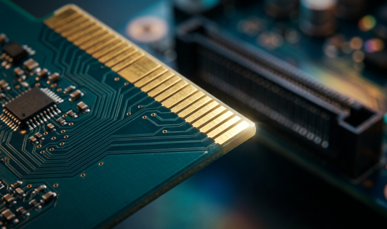
One of those things, when it works, you don't see it, and when it doesn't, you can't stop banging your head. With this article, I'd like to describe what a beveled edge is, why it's so important for Gold Finger connectors and Gold Card Edge connectors, and how to specify it correctly. We will be discussing bevel angles, depth control, design compromises for board strength, and manufacturing tolerances required to make it work. At the end, you will have a good idea of what to request from your fabricator.
Understanding Bevel Edge in PCB Manufacturing
What a Beveled Edge Is and Its Primary Purpose
A beveled edge is the angled edge (chamfer) of a PCB (where the gold fingers are) that is cut. The board is not 90° at the edge; it tapers off at a controlled angle to make the leading edge thinner than the board. Mechanical guidance is the main function. The chamfer serves as a ramp to gently create a lift and distribute spring contacts within the slot when the board is inserted into an edge connector. Otherwise, the square edge of the board will slam into those contacts. That's how it translates in practice:
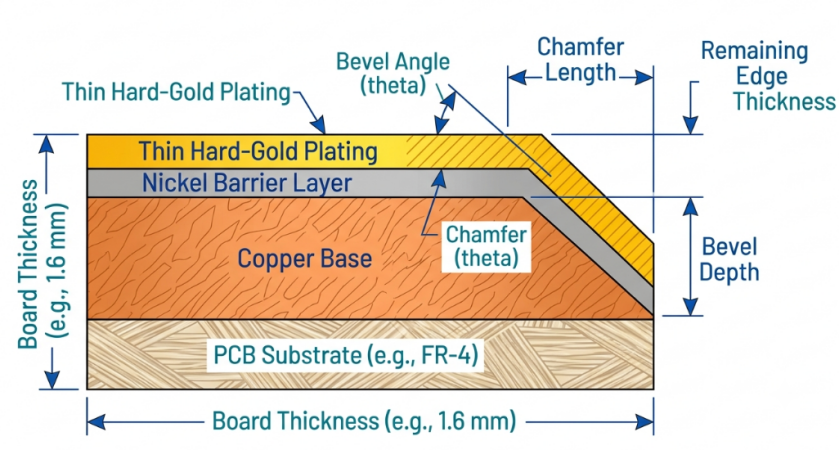
- Smooth insertion: Tapered edge for smooth insertion under the connector springs, rather than butting against them.
- Plating protection: Contacts do not scrape along the flat gold surface, but are lifted up the bevel.
- Alignment guidance: This is guidance to self-center the board in the slot.
- Reduced insertion force: Less stress on the board and the connector housing due to reduced insertion force.
Common Applications in Gold Finger and Card Edge Designs
Beveling appears at all the places where a bare-board edge is making a direct connection with a mating connector. The gold fingers are called contacts, and the slot into which they fit is called the card edge connector. Typical applications include:
- Memory modules are DDR DIMM and SO-DIMM boards that can mate hundreds of times during their lifetime.
- Add-on cards (PCIe graphics, network, storage cards) are added to motherboards.
- Backplane edge connectors: Boards that fit in the backplane of a rack or chassis.
- ISA/PC/104 edge finger and instrumentation cards and Legacy cards.
All of these need to have a gold finger, which provides power and high-speed signals, so the integrity of the contact is not an option. A beveled edge ensures that those contacts remain clean and well-mated cycle after cycle. That's why every standard memory and add-in card specification assumes that one exists.
Key Benefits of Using Beveled Edges
Smoother Insertion, Reduced Wear, and Extended Connector Life
The first and most obvious advantage is that the insertion force and wear are dramatically reduced. A square edge will be a sharp angle against the spring contacts of the connector, and high local pressure will exist, and a scraping action across the Gold will occur. With a beveled edge, that geometry gets turned upside down. The contacts slide along a gentle slope so that the force is distributed and the movement is a slide and not a scrape. This means that less metal is removed in the gold finger plating and the connector contacts on each cycle.
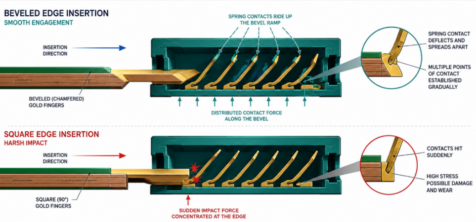
That is important because for high-cycle connectors, the hard gold plating over nickel is thin, in the 0.76 to 1.27 micron (30 to 50 microinches) range. With each aggressive insertion, a bit is shaved off. If you can protect that layer, you have protected the whole connection:
- Fewer mating cycles lead to less wear through to the nickel barrier.
- Reduced peeling and flaking of gold on the leading edge.
- Connector springs retain their contact force for a longer period of time.
- The socket and board counter is used up to its stated cycle count.
Improved Mechanical Stability and Contact Reliability
The bevel not only makes the board easier to wear, but it also enhances the secure fit of the board. Chamfer snaps the card in place as it slides in, bringing the fingers into perfect alignment with their counterpart contacts in the slot's centerline. Good seating equals reliability of electrical connections. When a board is inserted cleanly and centered, it will ensure full contact by all of its fingers, keeping contact resistance low and constant. A crooked board may result in some under-engaged contacts. This is particularly important when working with high-speed interfaces. At the PCIe and DDR edges, the finger not being seated correctly results in an impedance discontinuity (or an intermittent open), and that is a miserable thing to debug. The bevel is a low-cost way to safeguard against any marginal contacts on the signals you're interested in.
Design Considerations for Effective Bevel Edges
Angle Selection, Depth Control, and Gold Finger Layout
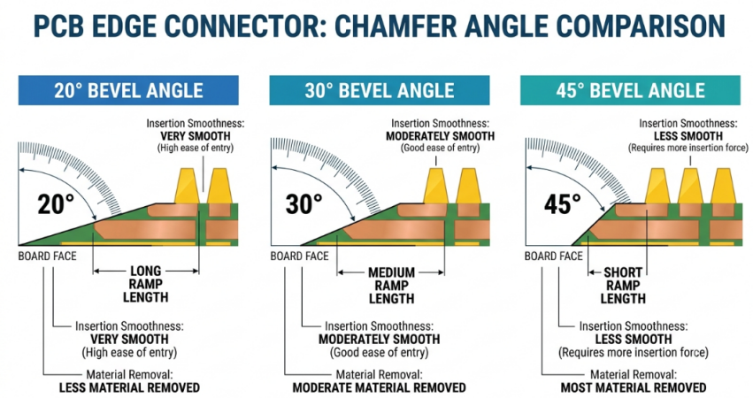
There are two numbers that make up a bevel: angle and depth. The angle is measured from the face of the board, and a few standard angles are the most popular possibilities.
| Bevel Angle | Typical Use | Insertion Feel | Notes |
|---|---|---|---|
| 20 degrees | Thicker boards, long lead-in | Very smooth, gradual | Removes more material; needs longer chamfer length |
| 30 degrees | General-purpose, most common | Smooth, balanced | Good default for standard 1.6 mm boards |
| 45 degrees | Standard card edge / PCIe-style | Firm but clean | Most widely specified; balances guidance and strength |
| 60 degrees | Thin boards, minimal lead-in | Shorter ramp | Less aggressive material removal |
In reality, 30 and 45 degrees are the most popular, with 45 degrees being the standard for PCIe and memory-style edges. The choice interacts with board thickness; a shallower angle means that a thick board will have a longer, gentler ramp, a steeper angle means a shorter, gentler ramp. Just like angle, depth control is also important.
Balancing Bevel Requirements with Overall Board Strength
The depth number is, in fact, a real trade-off. A larger bevel will provide a more seamless insertion; however, it will also take material from the most stressed edge of the board. It's that thin edge that bears insertion and extraction forces. If it is cut too deeply, it could lead to an eventual chipped leading edge, delamination, and/or cracking. The aim is to cut enough laminate to remove the direct contacts, yet keep a strong spine of laminate in place. A sensible bevel is to bevel the board down to about 1/3 to 1/2 of its thickness (for a standard 1.6 mm board). Thinner boards require shallower bevels since there isn't as much that can be sacrificed.
Manufacturing Challenges and Precision Solutions
Controlling Bevel Quality and Consistency
A repeatable and consistent outcome requires a number of steps to happen in a particular sequence. Quality issues are primarily:
- Angle accuracy: The wheel and fixture would need to be within a very close tolerance of the specified angle along the entire edge of the wheel.
- Depth uniformity: The chamfer must be the same depth from one end of the finger array to the other.
- Edge finish: The cut should be smooth and free of burrs, fraying, or fiberglass splintering that may snag a contact.
- Plating integrity: Beveling exposes the laminate at the tip, and the process must not lift or peel the adjacent gold.
Process Optimization for Different Board Thicknesses
Not all boards are 1.6 mm, and the bevel process needs to accommodate this. Even if the connector family is the same, a 0.8 mm card requires different feeds, angles, and depths compared to a 2.4 mm backplane edge. Some of the important optimization levers are:
- Angle scaling: the boards are often thinner and require steeper angles to maintain a usable lead-in, whilst not cutting away too much material.
- Feed rate tuning: Thick FR4 requires lower feeds to avoid splintering; thin stock can be fed at higher rates.
- Depth setpoints per thickness: the remaining-tip target is recalculated for each stackup.
- Wheel selection: grinding grit and profile adjusted according to the thickness of the laminate and the amount of copper on the edge.
JLCPCB's Expertise in High-Quality Bevel Edge Processing
Advanced Beveling Equipment and Tight Tolerance Control
JLCPCB uses special edge-beveling equipment that maintains the angle and depth throughout the entire contact edge. This includes standard chamfer angles of 30 and 45 degrees, and the cut is produced to provide a clean, burr-free edge to preserve the adjacent gold plating.

That tight control is what matters; it's consistency. Keeping the angle and depth within tolerance between boards allows your gold fingers to mate the same way each time. Which is what high-cycle connectors and high-speed interfaces are all about.
Comprehensive DFM Review for Edge Connector Designs
A good DFM (Design for Manufacturing) review identifies problems before they are too costly to correct. That review focuses on the things designers often overlook in edge connector designs. Good DFM pass:
- Bevel angle and depth that contravenes board thickness or connector spec.
- Gold finger geometry that does not provide a clean chamfer.
- Paying and tolerance interaction at the final fingertips.
- Edge clearances that could potentially cut into features you were looking to preserve.
It is a lot better to do this than to do it after the boards are delivered – otherwise you will have a respin and delay. The end product is boards with gold-finger edges that have been beveled correctly, and are available with fast turnaround and instant online quoting. Controlled chamfer angles, prototype-friendly pricing, and hard gold plating are available to help you obtain a card-edge design without a reliability tax.
FAQ about PCB Bevel Edge
Q: What is a beveled edge on a PCB, and why is it needed?
A beveled edge is an angled chamfer cut along the contact edge where the gold fingers sit, so the board can slide smoothly into an edge connector. It reduces insertion force, protects the gold plating from scraping, and helps the board self-align in the slot.
Q: What bevel angle should I use for a card edge connector?
The two most common angles are 30 and 45 degrees, with 45 degrees being the typical default for PCIe and memory-style edges. The right choice depends on board thickness and the connector standard, so a shallower angle on thicker boards and a steeper one on thin boards is a reasonable rule of thumb.
Q: Does beveling weaken the edge of the board?
It removes material at the contact edge, so an overly deep bevel can risk cracking or delamination. The goal is to leave a robust amount of laminate at the tip — often around a third to a half of the board thickness on a standard 1.6 mm board — balancing smooth insertion against edge strength.
Q:When in the manufacturing process is the bevel cut?
The chamfer is machined after routing and gold-finger plating, using a dedicated beveling machine with an angled cutting wheel. Because it is done on a finished, plated edge, the process must be burr-free and controlled so it does not peel the adjacent gold.
Q: Do all gold-finger boards need a beveled edge?
Boards whose fingers plug directly into an edge connector, such as memory modules and add-in cards, almost always need one for smooth, low-wear insertion. Gold fingers used only as contact pads that are not repeatedly inserted into a slot may not require a bevel at all.
Conclusion
Among the many little things that make a card-edge connection "a winner" or "something I don't want to keep doing" is a beveled edge. It converts destructive square edge collision into a controlled glide, ensuring that thin hard-gold plating is protected, insertion force is reduced, and the board self-aligns to ensure that each finger seats cleanly. None of this is glamorous, but all of these come through in the long-term reliability.
It is largely about conscious specification of a sensible angle (typically 30 or 45 degrees), depth to guide the contacts without compromising the edge, and a fabricator with the ability to maintain that angle throughout the thickness of your board. To ensure the edges of gold-finger boards are beveled properly and well controlled, JLCPCB's beveling capability, DFM review, and fast and cheap production make it easy to implement these principles and keep the contact edges smooth and reliable cycle after cycle.
Keep Learning
How Laser-Made PCBs Are Used in Rapid Prototyping
Key Takeaways Speed & Precision: Digital lasers enable 24-hour quick-turn HDI and FPC prototyping without mechanical tooling. LDI Patterning: Replaces physical photo-films to deliver precise circuit traces down to 2/2 mil. HDI Microvias: UV/CO2 lasers drill 0.075–0.15 mm blind vias (1:1 aspect ratio) for 1+N+1 to 3+N+3 stackups. Laser Profiling & Stencils: Achieves ±0.05 mm FPC cut accuracy and ±0.003 mm LPKF stencil aperture precision. Laser DFM: Maintain ≥ 0.30 mm copper clearance on FPCs and ≥ 0.07......
A Beginners Guide to Tented vs Untented Vias
Via’s are important, If working at high speed design and HDI boards then they become super important. Choosing a type of via during PCB manufacturing matters. Via’s are basically joining two or more layer traces together. Shape, size and track length guidelines became more interesting at high frequency and high speed signals. Today in this article we will explore a fabrication side, the decision to use tented or untented vias. This beginner-friendly guide explains what tented vias are, the differences......
Understanding SMT PCB Boards Technology: An Essential Component of Modern Electronics
Surface Mount Technology (SMT) has changed manufacturing of modern electronics. It has made designs and assembly methods more efficient. Many modern electronics depend on SMT PCB boards, which make it possible for circuit designs to be small and efficient. This is what today's technology needs. This article discuss about many types of SMT PCB boards, their uses, and the best methods for designing and assembling them. 1. What is an SMT PCB Board? Printed circuit boards called SMT PCB boards, use surfac......
How to Choose the Right Prepreg Material for Reliable Multilayer PCB
Have you ever wondered what makes all those copper layers stick to a cross-section of a multilayer PCB? Prepreg material is the answer, and it is of much more importance than most engineers think it is. Choose the prepreg selection wrong, and you are predetermined to delamination, impedance drift, and long-term reliability problems. Prepreg is not only glue. It is a designed composite that determines your dielectric separation, dictates your impedance, affects signal loss, and determines your board be......
Via Filling Explained: Key Techniques, Benefits, and Solutions for High-Performance PCBs
Key Takeaways Via filling completely fills plated through-holes and microvias with epoxy or conductive copper paste, followed by planarization and copper capping (POFV). It eliminates voids, solder wicking, and thermal/mechanical issues while enabling reliable via-in-pad designs. Benefits include superior heat dissipation (up to 8 W/m·K), better signal integrity, higher mechanical strength, and improved assembly yields. JLCPCB provides free non-conductive filling + POFV on 6+ layer boards. Ideal for H......
How Fiducial Markers Guarantee Perfect Alignment in Professional PCB Fabrication
Today, the most sophisticated pick-and-place machine can place a 0.5 mm pitch QFP on its footprint, board after board, thousands of times, and never miss. It is not only a matter of expensive cameras or high-quality servos, but it begins with a little, very small copper dot, simply hanging there in the corner of your PCB. That dot represents a fiducial marker, and without it, even the smoothest SMT line would be laying components in the dark. The unrecognized heroes of automated assembly are the fiduc......