
Inductor Symbol Guide: Different Types & Circuit Diagram Examples
9 min
- What Is an Inductor Symbol in Circuit Diagrams
- Inductor Types and Symbols
- How to Read an Inductor Symbol in Circuit Diagrams
- Common Mistakes When Identifying Inductor Symbol
- Real Examples of Inductor Symbol in Circuit Diagrams
- Inductor Symbol vs Other Circuit Symbols
- How an Inductor Works (Magnetic Field & Energy Storage)
- Inductor Dot Convention & Phase Relationship
- Inductor Symbol in PCB Design & Real Manufacturing Considerations
- FAQs about Inductor Symbol
- Conclusion
In electronics, an inductor symbol is the standard graphical representation of a coil used to visualize schematics. Technically, it denotes a passive two-terminal component that resists changes in electric current by storing energy within a magnetic field. Understanding the inductor symbol meaning is crucial, whether you are designing a complex buck converter or diagnosing a simple radio circuit.
What You Will Learn
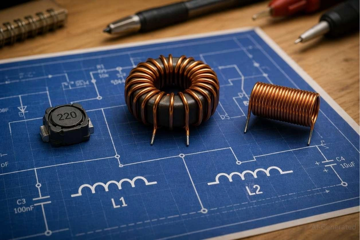
Figure: Various physical inductors placed on a circuit schematic showing different inductor symbol diagrams.
What Is an Inductor Symbol in Circuit Diagrams
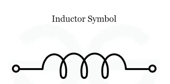
Figure: Standard inductor symbol diagram drawn as a wire coil representing inductance in a circuit.
The inductor schematic symbol is universally drawn as a series of connected semi-circles or loops. This coil representation mirrors the physical wire wound around a core, with its inductance value measured in Henrys (H) and denoted by the letter "L".
Key Functions of Inductor Symbol:
- Stores energy in a magnetic field
- Opposes rapid changes in current
- Used in power conversion, RF, and filters
Why Inductor Symbol Is Used in Circuit Diagrams
- Represents electromagnetic energy storage
- Shows the filtering role for high-frequency noise
- Indicates inductive behavior within a specific sub-circuit
Where Inductor Symbols Are Used (Power, RF, Filter Circuits)
- Power supplies (switching regulators)
- RF circuits (tuning and matching networks)
- Filters (low-pass, high-pass, band-pass)
Inductor Types and Symbols
The most common electronic inductor symbols used in circuit diagrams include variations based on the core material (air, iron, ferrite) and adjustability (fixed, variable, pre-set). Understanding the air core vs iron core inductor symbol is crucial for proper component identification.
The most common types of inductor symbols in circuit diagrams include:
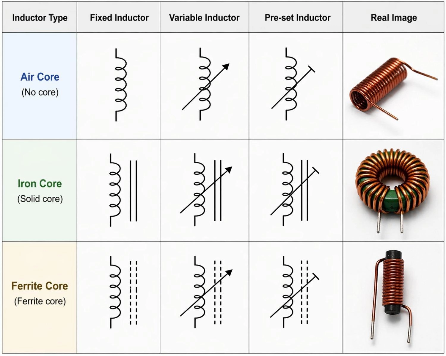
Figure: Showing schematic symbols for fixed, variable, and pre-set inductors across air core, iron core, and ferrite core types, alongside real component photos.
Air-Core Inductor Symbol
- No core lines
- Used in RF circuits
Iron-Core Inductor Symbol
- Solid parallel lines
- Used in power circuits
Ferrite Core Inductor Symbol
- Dashed lines
- High-frequency use
Variable Inductor Symbol
- Diagonal arrow
- Allows tuning
Pre-set Inductor Symbol
- Diagonal line ending in a flat "T-bar"
- Used for one-time calibration
Tapped Inductor Symbol
- Intermediate wire tap
- Used in voltage stepping
| Inductor Type | Symbol Feature | Common Application |
|---|---|---|
| Air-Core Inductor | No core lines drawn alongside the coil. | High-frequency RF applications. |
| Iron-Core Inductor | Two solid parallel lines above or next to the coil. | Low-frequency, high-power circuits. |
| Ferrite Core Inductor | Dashed parallel lines alongside the coil. | High-frequency, minimized eddy current losses. |
| Variable Inductor | An arrow drawn diagonally across the standard coil. | Adjustable inductance, radio tuning. |
| Tapped Inductor | A coil with one or more intermediate wire connections (taps) branching off. | Voltage step-up/down, impedance matching. |
| Pre-set Inductor | A diagonal line ending in a flat bar across the coil. | Factory-calibrated tuning, rarely adjusted by end-users. |
| Coupled Inductor | Two coils drawn side-by-side, separated by core lines. | Transformers, isolated flyback power supplies. |
How to Read an Inductor Symbol in Circuit Diagrams
Follow these steps when learning how to read inductor symbol diagram schematics quickly:
Step 1: Identify coil shape
Look for the classic looping wire drawing and the "L" reference designator to confirm it is an inductor rather than a resistor.
Step 2: Check core lines
Observe if there are solid lines (iron core), dashed lines (ferrite core), or no lines (air core) to quickly determine the magnetic material used.
Step 3: Look for arrow (variable)
A diagonal sweeping arrow across the symbol indicates that the component's inductance value is manually or electronically adjustable.
Step 4: Analyze circuit role
Examine surrounding components to determine if it acts as a power choke, a high-frequency filter, or an energy storage element.
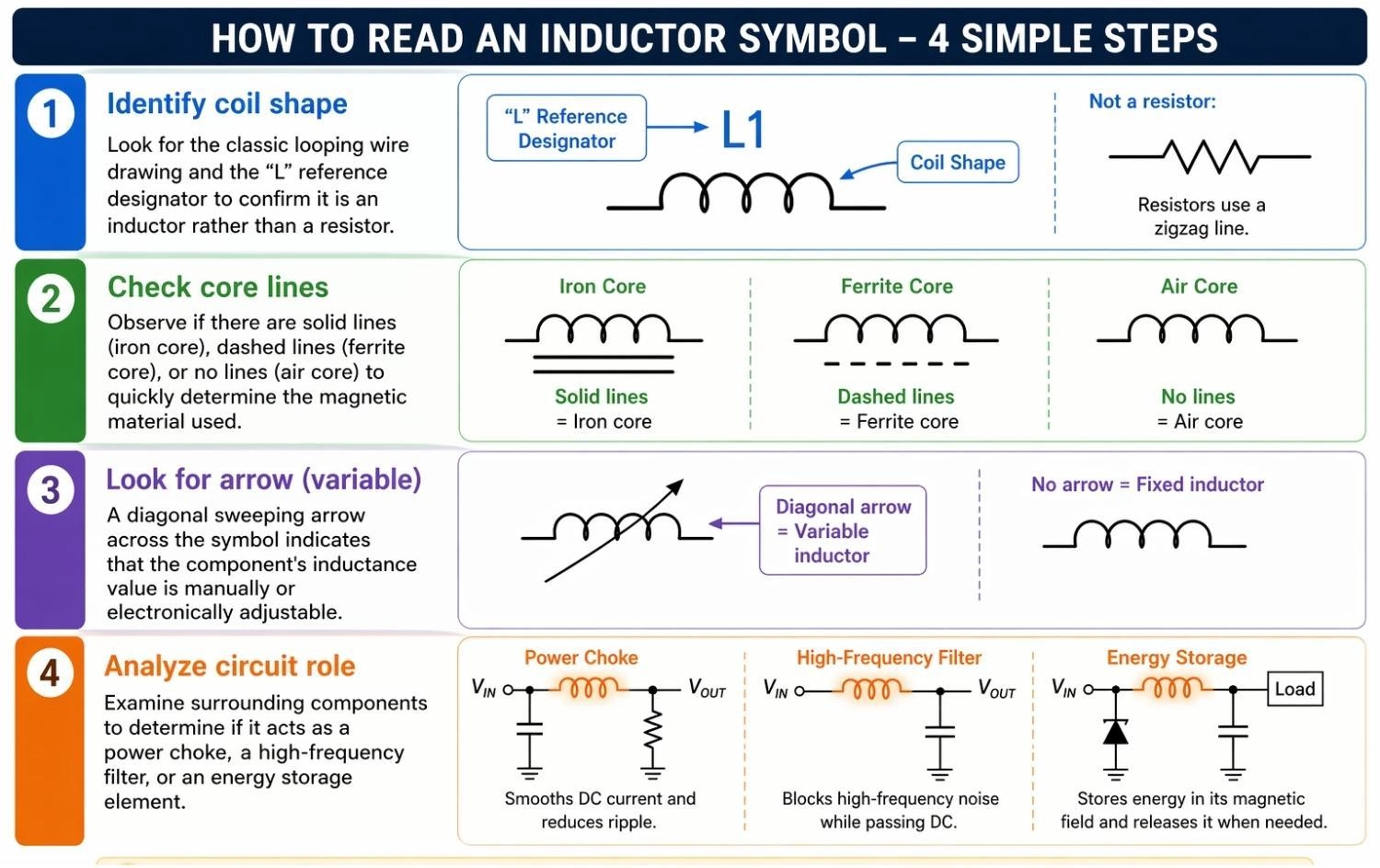
Figure: Showing how to identify the coil shape, check core lines, look for variable arrows, and analyze the circuit role of an inductor symbol.
Common Mistakes When Identifying Inductor Symbol
1. Confusing a transformer symbol with a standard coupled inductor symbol.
2. Ignoring core lines, leading to the wrong component selection in high-power applications.
3. Missing the inductor dot convention, causing inverted phases in switching converters.
Real Examples of Inductor Symbol in Circuit Diagrams
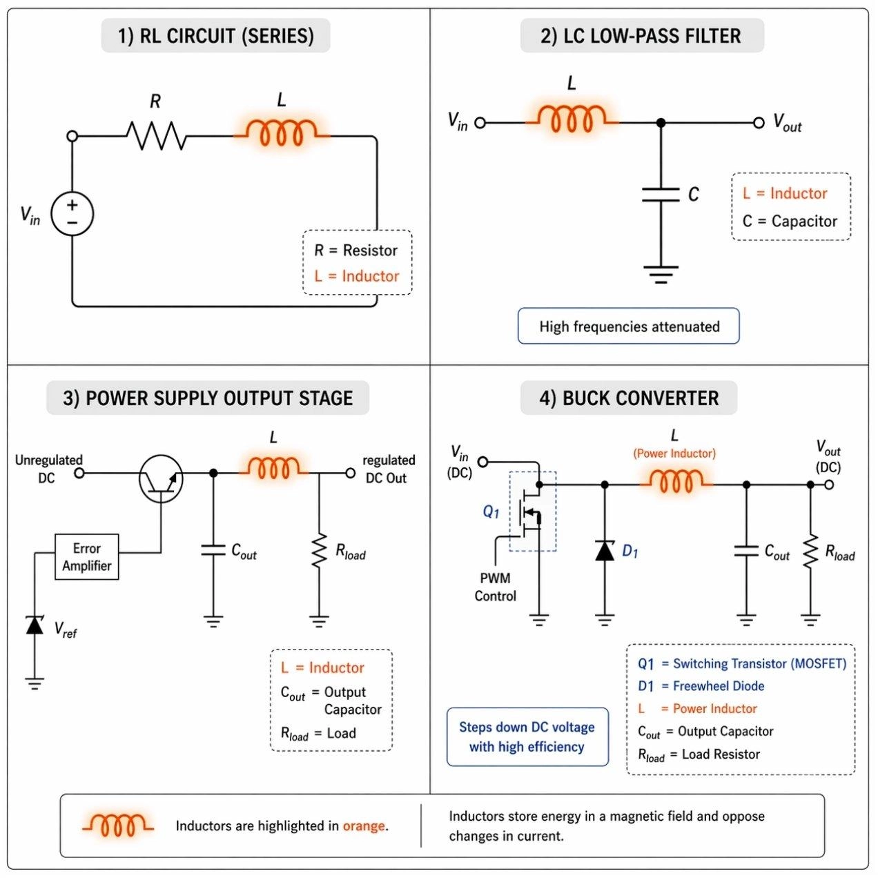
Figure: Examples of inductor symbols used in RL circuits, LC filters, and buck converter schematics.
These examples show how the inductor symbol diagram is utilized in real-world circuit designs:
1. RL Circuit Diagram
- Smooths current spikes by resisting rapid changes.
- Introduces a calculated timing delay in signal processing.
2. LC Filter
- Blocks high-frequency EMI noise from reaching sensitive ICs.
- Pairs tightly with a capacitor to create a specific resonance frequency.
3. Power Supply
- Stabilizes final DC output voltage against sudden load fluctuations.
- Acts as a choke to limit and filter out high-frequency AC ripple.
4. Buck Converter
- Stores magnetic energy during the switching transistor's "on" state.
- Releases energy to smoothly step down DC voltage with high efficiency.
Inductor Symbol vs Other Circuit Symbols
Comparing the inductor symbol vs capacitor symbol helps prevent costly schematic reading errors during PCB design.
Inductor vs Capacitor
Inductor Symbol
- Coil shape
- Stores magnetic energy
Capacitor Symbol
- Parallel plates
- Stores electric charge
Further read: The Engineering Guide to Capacitor Symbols: Schematic Standards and Polarity
Inductor vs Resistor
Inductor Symbol
- Rounded loops
- Opposition depends on AC frequency
- Zig-zag shape
- Limits current regardless of frequency
Inductor vs Transformer
Inductor Symbol: Single coil
Transformer Symbol: Two coupled coils
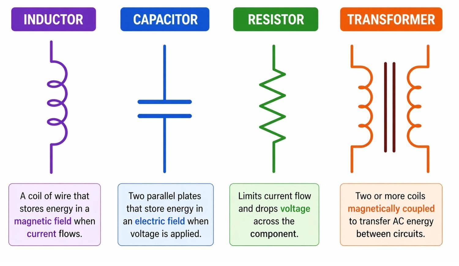
Figure: Comparison of basic electronic symbols showing an inductor, capacitor, resistor, and transformer.
How an Inductor Works (Magnetic Field & Energy Storage)
Why the Inductor Symbol is Drawn as a Coil in Circuit Diagrams
The visual coil design directly mimics the physical construction of an inductor. It represents a copper wire wound into loops, a structure specifically designed to maximize magnetic coupling and inductance.
Magnetic Field Behavior in an Inductor
When current flows through the component represented by the inductor symbol, it generates a proportional magnetic field around the coil. This field dynamically grows and collapses as the alternating current (AC) changes state.
How Inductors Affect Current Flow
The inductor resists sudden current changes. If the current shifts rapidly, the coil creates a reverse voltage (back EMF). It acts as a temporary energy buffer, storing power in its magnetic field and releasing it to maintain steady current flow.
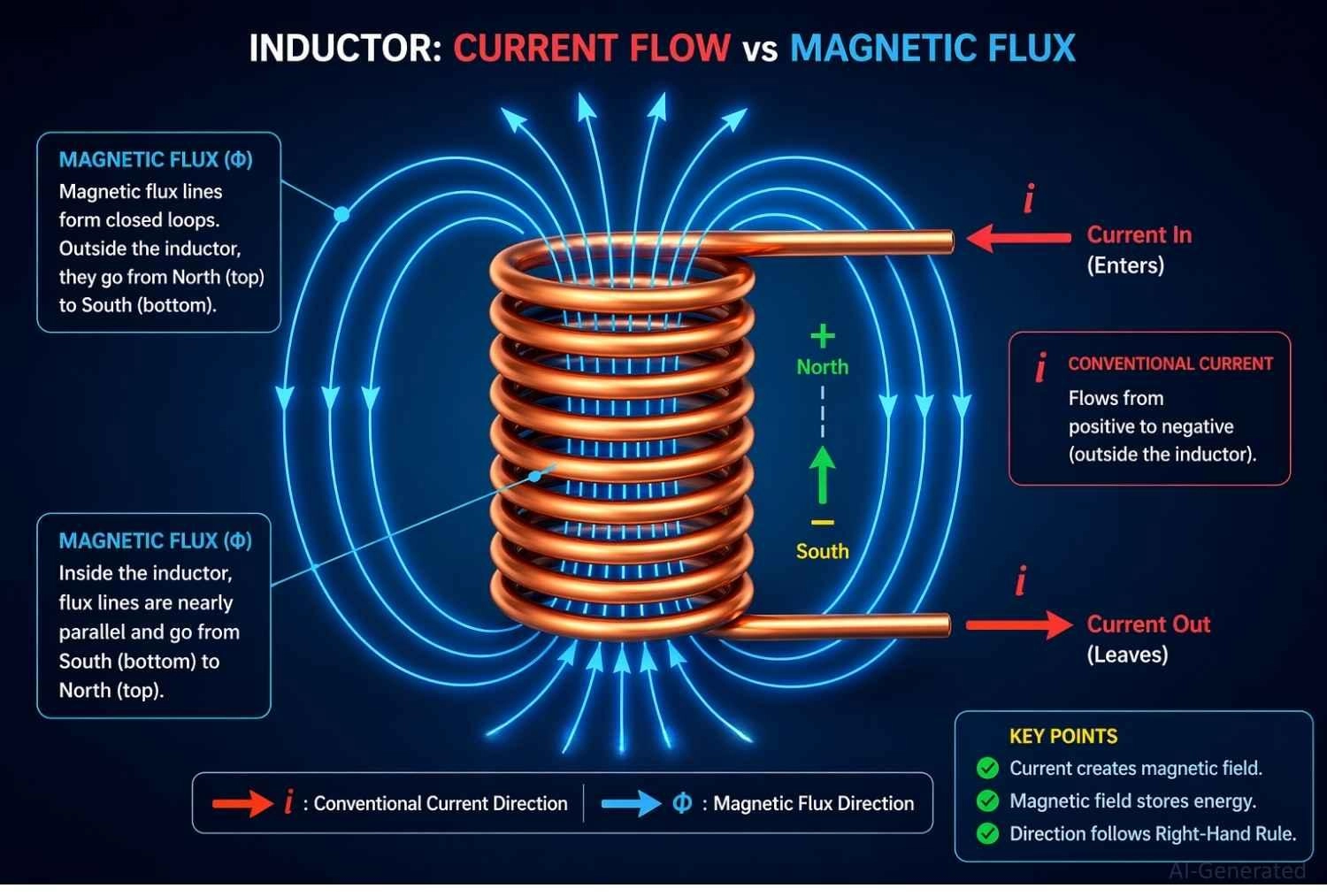
Figure: An inductor's magnetic field formation as electric current flows through the component.
Inductor Dot Convention & Phase Relationship
Inductor Dot Convention Explained in Circuit Diagrams
The inductor dot convention is a standard marking used in complex schematics involving magnetic coupling. These small, solid dots placed near the coil terminals show the phase relationship between mutually coupled coils, indicating exactly how their magnetic fields interact - whether they add together or cancel each other out.
Current Direction and Dot Convention Rule
According to Faraday's Law of Induction:
- If currents enter the dotted terminals of both coils, the resulting magnetic fluxes are additive (in-phase)
- If current enters the dotted terminal of one coil and leaves the dotted terminal of the other, the fluxes oppose (out-of-phase)
This rule defines the induced voltage polarity between coupled windings.
When Dot Convention Matters in Circuit Design
- Transformers requiring exact AC phase alignment (such as audio and RF signal transformers)
- Coupled inductors in isolated flyback power supplies (dictating when energy is stored versus when it is transferred to the load)
- Common-mode chokes used for filtering EMI noise, where coils must be wound in specific opposing directions
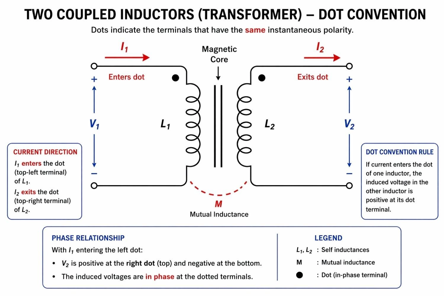
Figure: Inductor dot convention diagram showing two coupled inductors with phase dots indicating current flow direction and phase relationship.
Inductor Symbol in PCB Design & Real Manufacturing Considerations
When translating an inductor symbol in circuit diagram to a physical board layout, precision is paramount. Incorrect inductor selection can cause overheating, noise issues, or power instability in real PCB designs.
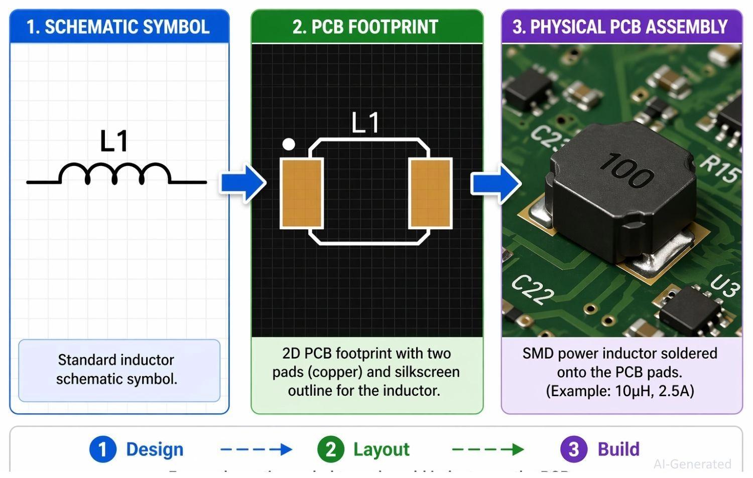
Figure: Showing an inductor schematic symbol translating to a PCB footprint and finally to a soldered physical SMD component.
Schematic to PCB Conversion
- Convert inductor symbol to footprint: Ensure the logical symbol in your schematic software is accurately linked to a physical footprint (like an 0805 SMD package).
- Verify pin connections: Double-check your netlist to ensure schematic symbol pins map perfectly to physical PCB pads.
Selecting Inductor Footprints
- Match inductance and current rating: Select a physical component that handles peak saturation current without overheating.
- Check SMD vs through-hole: Choose Surface Mount Devices (SMD) for compact, automated assembly, or through-hole for mechanical stability.
PCBA Manufacturing for Inductors
When your schematic is finalized and you're ready to move from design to production, JLCPCB provides a fast and reliable solution for both PCB fabrication and assembly:
- Upload Gerber files: Generate and upload your final Gerber and Drill files for rapid and precise bare-board fabrication.
- Use PCB Assembly services: Save time and ensure high-quality, consistent solder joints by utilizing automated SMT assembly for accurate inductor placement
- Extensive Component Library:
Access a wide range of in-stock inductors, helping you reduce sourcing time and accelerate your project timeline.
FAQs about Inductor Symbol
Q: What does an inductor symbol represent?
It represents a passive component that stores energy in a magnetic field when electric current flows through it.
Q: Why is an inductor drawn as a coil?
The symbol mimics the physical construction of an inductor, which is typically a wound copper wire.
Q: Do inductors have polarity?
Standard inductors do not have polarity. However, coupled inductors use a dot convention to indicate phase polarity.
Q: What do lines on an inductor symbol mean?
Solid lines indicate an iron core, while dashed lines mean a ferrite core. No lines indicate an air core.
Q: What is the difference between inductor and transformer symbol?
An inductor symbol shows a single coil, while a transformer symbol displays two or more coils separated by core lines.
Conclusion
The inductor symbol explained in this guide serves as the foundation for reading and designing electronic schematics. From identifying an air core vs iron core inductor symbol to mastering the precise phase relationships of the dot convention, these visual cues dictate hardware behavior.
Whether you are filtering noise in an RF module or stabilizing a power supply, correctly interpreting these symbols ensures your physical board matches your theoretical design.
Popular Articles
• How to Identify SMD LED Polarity: Markings, Testing, and PCB Tips
• How to Create a Bluetooth-Controlled Car With Arduino: A Step-by-Step Guide
• How to Design and Assemble a Reliable ESP32 Module PCB on a 2-Layer Board
• The Ultimate Guide to Relay Symbol: Coil, Contacts, Diagrams, and Circuit Applications
• The Ultimate Guide to PCBA: Process,Types and Techniques for the Electronics Enthusiast
Keep Learning
How to Design an ESP32-S3 Development Board from Scratch: A 4-Layer PCB Design Tutorial
Designing your own ESP32-S3 development board gives you complete control over your hardware architecture while preparing your IoT projects for commercial production. Instead of relying on bulkier, off-the-shelf boards, building a custom design allows you to optimize the board space, expose only the required GPIO pins, and integrate peripherals directly onto a single substrate. In this tutorial, we will design a 4-layer ESP32-S3 development board from scratch. We will walk through the entire hardware d......
Circuit Breaker Symbols Explained: IEC, ANSI, MCB, and Pole Configuration Symbols
Electrical schematics are the universal language of power systems, control circuits, and printed circuit boards. Within these diagrams, the circuit breaker symbol is one of the most critical elements. Getting it right is essential for safety, troubleshooting, and manufacturing. An error as simple as mixing up a circuit breaker with a manual switch or an isolator can lead to catastrophic misinterpretations on the factory floor or during field maintenance. This guide provides a complete, technically acc......
How to Identify SMD LED Polarity: Markings, Testing, and PCB Tips
Surface-mount LED components are ubiquitous in electronics design, serving as everything from simple power indicators to complex lighting arrays. Unlike standard resistors, LEDs are polarized diodes. Identifying SMD LED polarity correctly is critical for prototype troubleshooting and high-volume PCB assembly. A reversed LED results in no light output, broken circuit paths, and potential diode breakdown if the reverse voltage exceeds the component's maximum rating (typically 5V or less for most indicat......
Arduino LED Driver Tutorial: Control More LEDs with 74HC595 and MAX7219
Arduino GPIO pins run out quickly in larger LED projects. By utilizing dedicated LED drivers and expansion ICs, you can drastically reduce pin usage, eliminate processor-heavy multiplexing loops, and simplify display wiring. In this guide, you will learn the operational architecture, wiring configurations, cascading techniques, and optimization strategies for the 74HC595 shift register and the MAX7219 LED driver. Why Arduino Projects Need LED Driver ICs Arduino GPIO and Current Limitations An ATmega32......
How to Create a Bluetooth-Controlled Car With Arduino: A Step-by-Step Guide
This tutorial walks through the complete engineering and implementation of a two-wheel Bluetooth RC car with an Arduino Nano module on a specially designed PCBA (Printed Circuit Board Assembly). While many hobbyists start by wiring motors and Bluetooth modules with jumper cables on a breadboard, this approach is prone to disconnection and signal noise. This guide upgrades that process by teaching you how to design a professional mainboard. Key Design Features Controller: Arduino Nano used as a plug-in......
Fiducial Marks in PCB and SMT Assembly: A Complete Guide to Accuracy and Design Rules
Modern Printed Circuit Boards (PCBs) are complex, integrating high-density components like 0.4mm pitch Ball Grid Arrays (BGAs), 0201 passives, and fine-pitch Quad Flat No-Lead (QFN) packages. In this advanced manufacturing environment, achieving placement accuracy measured in micrometers is crucial. A significant challenge in automated manufacturing is how pick-and-place machines, which handle thousands of components per hour, precisely locate the PCB. A board on a conveyor system is never in the perf......