
Top 5 PCB Soldering Defects and How to Prevent Them
9 min
- What Are the Most Common PCB Soldering Defects And Why They Happen?
- Soldering Iron vs. Solder Paste Stencil: Choosing the Right Tool for the Job
- Pro Tips: How to Use a Stencil to Achieve Flawless Hand Soldering?
- How to Order Your High-Precision Stencil from JLCPCB in 5 Minutes?
- Fixing Mistakes: Essential Rework Tools for Every Maker
- Conclusion: Professional Quality Is Closer Than You Think
- Q: What is the finest pitch a laser-cut stencil handles reliably?
- Q: Does solder flux type matter for SMD work?
- Q: Why do solder balls appear even when I use a stencil?
- Q: Solder wick or solder sucker, which is better for SMD rework?
PCB design takes hours of careful work. You verify every trace and check every footprint. However, a single solder bridge or a brittle cold joint can ruin the entire project. Soldering defects like these can be an immense frustration for every engineer out there.
While a good soldering iron is essential, manual assembly has limits as components get smaller. That's where you have to approach the whole thing with strategy. Identifying the common defects isn't rocket science once you know what to look for.
In this guide, you get the 5 common PCB soldering defects and ways to prevent them. Let's get into it.
What Are the Most Common PCB Soldering Defects And Why They Happen?
Nearly every defect traces back to three variables: heat, volume, and alignment. Here is a diagnostic breakdown of what you will most likely encounter and what is actually driving each failure.
Solder Bridge:
A PCB solder bridge; This consists of two electrically isolated pads that are connected by excess solder. Mostly affected by them are fine-pitch packages such as QFN, TQFP, and 0201 passives, where pad gaps may be less than 0.2 mm. Slight paste excess or uneven reflow pulls molten metal sideways into that gap. These bridges are invisible to the naked eye but lethal to circuit function.
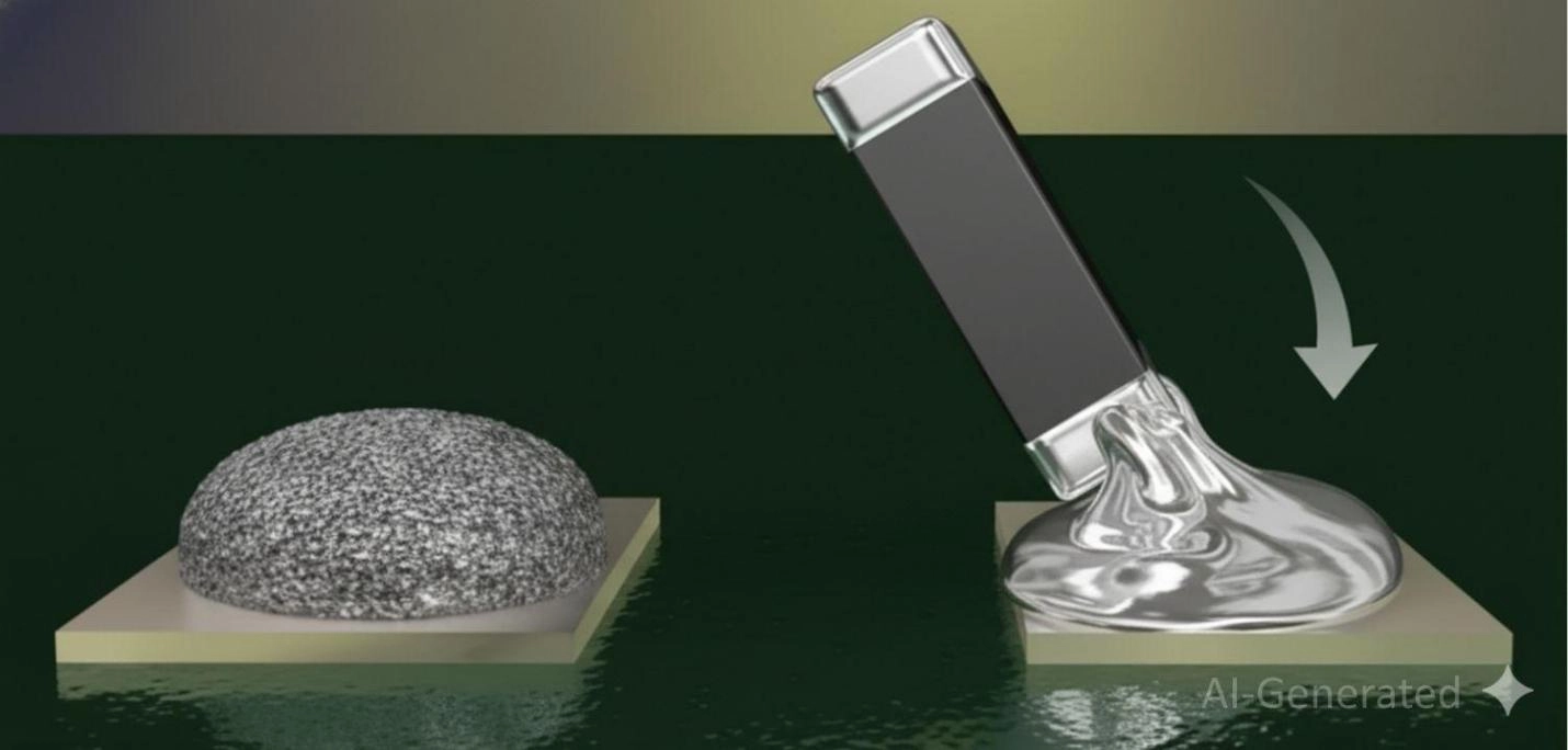
Cold Solder Joint:
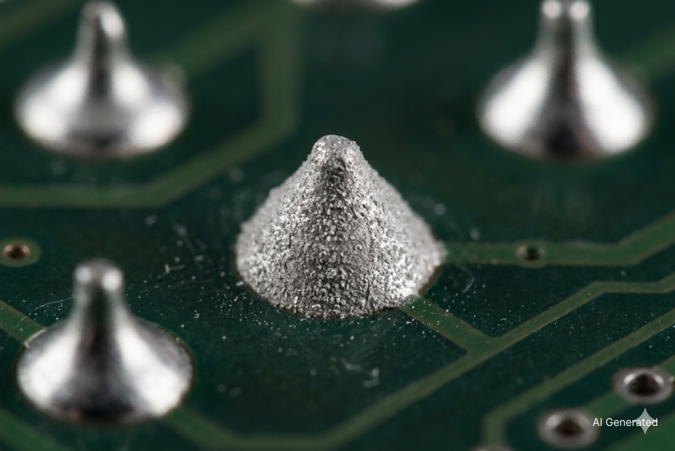
The iron or the oven does not reach a high temperature of reflow, and the solder does not completely melt, thus adhering to the pad and the lead before wetting. It has a dull, grainy surface instead of a smooth and shiny one, is brittle to vibration, and unstable to thermal cycling. Poor solder flux coverage makes it worse: surface oxides block wetting even when the heat is technically adequate.
Tombstoning:
If one pad of a small passive reaches liquidus first, surface tension yanks the component upright. Tombstoning solder defects hit 0402 and 0201 components hardest. The cause is almost always asymmetric thermal loading from uneven paste deposits, mismatched pad sizes, or off-center placement.
Solder Balls:
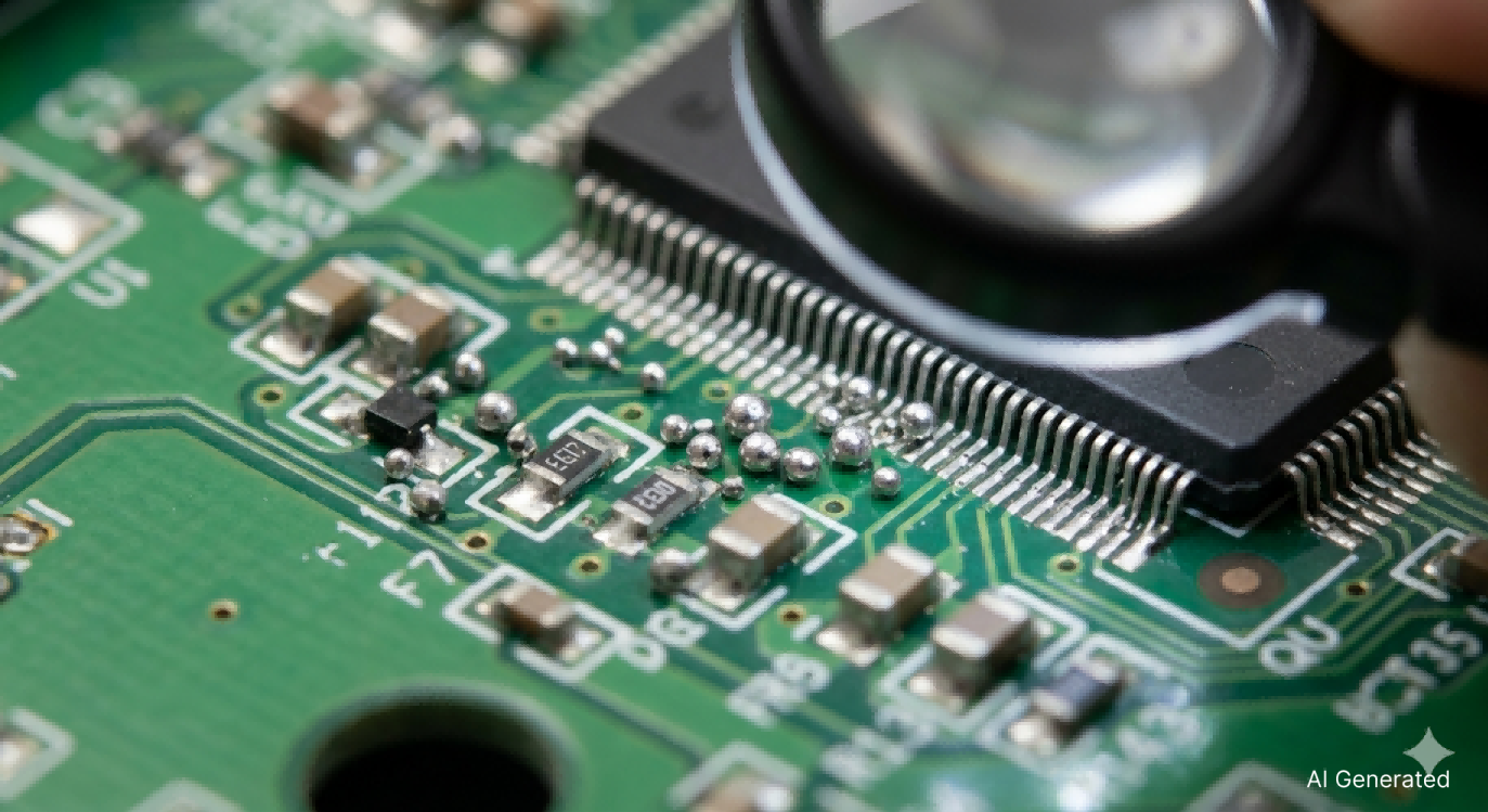
Tiny beads scattered near a joint are not cosmetic. Anyone sitting between fine-pitch pins is a potential short. Solder balls form when moisture in the paste vaporizes during reflow preheat, spattering molten droplets outward. Paste that absorbed humidity, an aggressive ramp rate, or paste outside the pad boundary all produce them.
Insufficient or Excessive Solder:
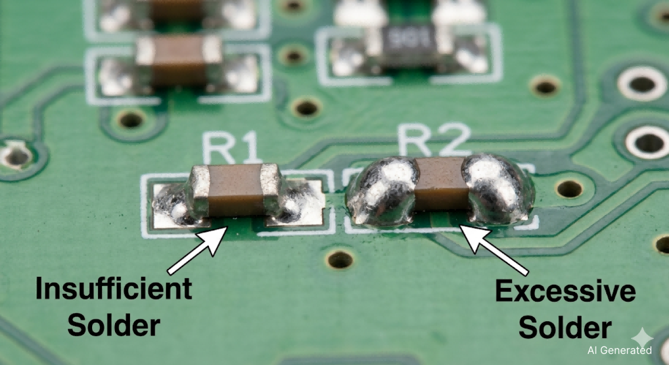
Under-wetted pads pass initial testing, then fail after a few thermal cycles. Too many solder bridges adjacent to pads or bury the lead. On through-hole boards, excessive solder is the classic hand-soldering mistake. Feeding wire until the joint looks shiny instead of watching the fillet form correctly.
Soldering Iron vs. Solder Paste Stencil: Choosing the Right Tool for the Job
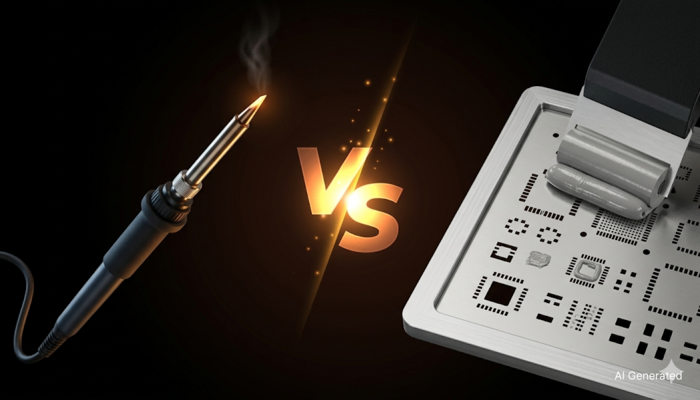
You need both. The question is knowing which one to reach for.
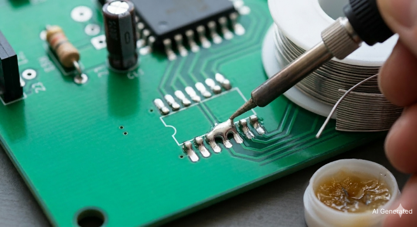
The Soldering Iron: The Versatile Classic
A temperature-controlled iron is irreplaceable for through-hole parts, wire connections, edge connectors, and spot rework. Nothing replaces the tactile feedback of drag-soldering 0.5 mm pitch leads.
Where it breaks down is scale and consistency. Applying identical paste volumes to 60 SMD pads by hand is genuinely difficult. Dwell time, tip angle, and wire feed rate drift subtly from pad to pad until rework starts eating more time than assembly.
The Solder Paste Stencil: The Precision Professional
A PCB stencil is a laser-cut stainless steel sheet with apertures that match exactly to every SMD pad. Place and trace solder paste using a squeegee over the board, then lift the pads in order to form a metered deposit on the pads. That gets rid of the two primary causes of SMT soldering defects, inconsiderate volume and misregistration.
Reflow and the paste collapses into clean, repeatable joints across the entire surface at once. First-pass yield climbs and rework time drops, whether you're building one unit or fifty. Take a look at our custom JLCPCB stencils to get a better idea.
Pro Tips: How to Use a Stencil to Achieve Flawless Hand Soldering?
Tip 1: Let the Aperture Control Volume
A well-designed SMT stencil sizes apertures using the area ratio formula. The aperture opening relative to the wall surface area governs how cleanly the paste transfers. Because every aperture is machined identically, every pad gets the same deposit. That uniformity makes solder bridging rare.
One catch: rough aperture walls cause smearing instead of clean release. This is addressed at the microscopic level using electropolished stencils, which visually enhances the quality of the deposit on small-pitch pads.
Tip 2: Hold the Squeegee at 45 Degrees
Angle matters more than pressure. At 45 degrees, the blade pushes paste into apertures while keeping the surface clean. Steeper and paste rolls ahead without filling; shallower and it smears. One smooth, continuous stroke outperforms short passes. Repeated strokes drag paste back out of apertures already filled.
Tip 3: Build a Quick Alignment Jig
Holding a stencil still while squeegeeing freehand is nearly impossible. Tape scrap PCB offcuts of matching thickness around three sides of your board to form a snug pocket. The board can't shift mid-stroke, and the stencil stays coplanar. Three minutes to set up, immediately visible improvement on 0402 and smaller.
Tip 4: Solder Flux Is Never Optional
Fresh paste contains solder flux, but for iron-based rework, adding flux before heat makes a real difference. It strips the oxide layer that blocks wetting. Afterwards, clean residue with flux remover. On high-frequency boards or anywhere leakage current matters, skipping that step is a slow route to reliability failures.
How to Order Your High-Precision Stencil from JLCPCB in 5 Minutes?
JLCPCB is producing stencils using 304 HTA stainless steel, of laser precision to +-0.003 mm. The cost starts at $3 USD, and it can take as fast as 12 hours to produce the parts, with no minimum order.
Now, let's get through the ordering process.
Three Ordering Methods:
There are three ways for you to order a stencil from JLCPCB.
Method A: Order with a PCB
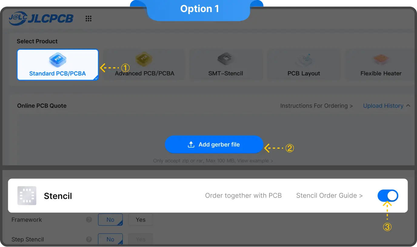
You can simply order a stencil along with your base PCB order. It works like an add-on option with the base PCB order. After selecting the PCB parameters, simply scroll down, and you will see a button on the right side of “Stencil”. Toggle it, to get the options for inputting all the details.
Method B: Order the stencil individually
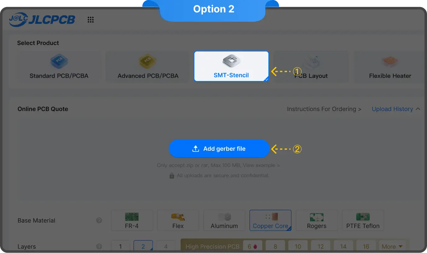
Another method is to order the stencil solely. Here, you simply go to the order now page and choose SMT-stencil from there. It will give you the option to upload gerber file, upload it, set the required parameters, and you are done.
Method C: Order from the PCB order history

If you already have a previous PCB order from JLCPCB, then you can use that to order a new stencil as well. To do that, just go to the order history and select the previous order. There, you will see a show all dropdown; click on that. Then, you will see a “Need stencil” option. Click on that to add your desired stencil.
Fixing Mistakes: Essential Rework Tools for Every Maker
Even a clean stencil-and-reflow workflow leaves finishing work. Connectors, through-hole parts, and the occasional shifted component all need manual attention.
Soldering Iron:
Still essential after reflow. Through-hole components, power terminals, and USB connectors do not go through the oven. A fine chisel tip handles drag-soldering fine-pitch leads and touching up bad solder joints that slipped through inspection.
Solder Wick:
Rosin-flux-impregnated braid pressed against a joint and heated draws molten solder out through capillary action. For clearing a solder bridge on fine-pitch pins, wick gives more control than a vacuum pump and won't lift a pad if used carefully.
Hot Air Rework Station:
Indispensable for removing SMD ICs, reflowing a cold joint cluster, or recovering tombstoned passives. Keep airflow low, apply flux first, and move heat slowly in circles around the component perimeter.
Flux Remover:
Rework leaves residue. On most boards, 99% isopropyl alcohol on a lint-free cloth handles it. On high-frequency paths or near fine-pitch ICs, purpose-formulated flux remover is more thorough. Some residues absorb moisture and create leakage paths exactly where you least want them.
Conclusion: Professional Quality Is Closer Than You Think
Soldering defects are no longer a matter of guesswork. A bridge means too much paste, while a tombstone indicates thermal issues. Using a precision stencil eliminates these variables and prevents most of these from even happening in the first place.
And when we speak of precision stencil, we have to mention JLCPCB. They offer high-quality, laser-cut stencils starting at just $1. With 304 HTA stainless steel and ultra-fast 12-hour production, you get industrial-grade results at an unbeatable price. Get a $11 stencil coupon and try it JLCPCB yourself.
Frequently Asked Questions:
Q: What is the finest pitch a laser-cut stencil handles reliably?
Electropolished stainless handles down to 0.3 mm pitch reliably. Below that, nano-coated or step stencils are the right tool. JLCPCB’s ±0.003 mm precision covers essentially every fine-pitch SMD package in current production.
Q: Does solder flux type matter for SMD work?
Significantly. No-clean flux leaves a non-corrosive residue convenient for production. Water-soluble requires extensive rinsing. Rosin is also beneficial in hand-soldering; it is always good to wash with the flux remover afterwards. Acid-core flux should not be used on electronics, as it causes copper corrosion.
Q: Why do solder balls appear even when I use a stencil?
Three causes: paste that absorbed humidity, a preheat ramp that climbs too fast, or paste deposited outside the pad boundary. Store paste at 0–10°C in a sealed container, use a proper reflow soak zone, and verify stencil alignment. Solve all three, and solder balls essentially stop.
Q: Solder wick or solder sucker, which is better for SMD rework?
Wick wins for fine-pitch SMD. It gives precise control and applies no mechanical force that could lift a pad. A solder sucker is faster for clearing through-hole barrels. On SMD pads, one careless pump stroke can peel the pad off the substrate
Keep Learning
Manual Pick and Place: A Cost-Effective SMT Alternative
Key Takeaways for Manual Pick and Place Manual pick and place uses a hand-held vacuum wand and positioning stage to place SMD components by hand, replacing tweezers in prototype assembly. It is most cost-effective for production runs of 1 to 50 boards, where an automated SMT pick-and-place machine cannot justify its $10,000+ setup cost. A complete manual workstation runs $300 to $500, compared with $10,000+ for an entry-level automated pick and place machine. SMT stencil quality is the single largest ......
Hot Air Surface Mount Soldering: A Step-by-Step Guide
Key Takeaways Heat Control Is Everything: Hot air SMD soldering delivers uniform heat across all pads simultaneously, eliminating the lifted pads and cold joints common with iron-based soldering of fine-pitch components. Airflow Kills Small Parts: Set airflow to just 10–20% for 0402/0201 passives to avoid the Bernoulli Effect that turns tiny resistors into projectiles. Stencil Precision Prevents Tombstoning: A precision-cut SMT stencil deposits equal paste volume on both pads, balancing surface tensio......
Solder Paste Printing Defects: How Precision Stencils Prevent Assembly Failures
Key Takeaways 70% Rule: Approximately 70% of SMT defects originate from the solder paste printing stage, making it the most critical process to optimize. Root Causes: Defects like bridging, insufficient paste, misalignment, and slumping are caused by stencil tension, process parameters (pressure, speed), and paste chemistry/environment. Area Ratio Matters: Maintaining an aperture Area Ratio (AR) above 0.66 (per IPC-7525) is essential to ensure proper paste transfer efficiency and prevent chronic insuf......
Best Manual Pick and Place Tools for Precise PCB Assembly
While fully automated robotic SMT lines handle mass production efficiently, every hardware innovation begins on a workbench. Engineers shifting from soldering large through-hole components to microscopic surface-mount devices (SMD) by hand quickly realize that precision and control are everything. Achieving factory-level assembly on your desk is absolutely possible with the right setup. This guide reviews the essential tool categories needed to build an effective prototyping workbench, covering precis......
How to Use a BGA Stencil for SMT Assembly and Reballing (Design & Process Guide)
Anyone who's spent time in a lab knows the look. You flip over a BGA chip and stare at the bottom. Flat. Featureless. No legs. No leads. Just a grid of tiny silver bumps. First thought? How the hell am I supposed to solder this? The Ball Grid Array (BGA) package is a trade-off. You get insane I/O density in a tiny footprint. But every single connection is hidden. You can't see them, and you can't poke them with an iron. Here's the thing I learned after lifting more pads than I'd like to admit: learnin......
Solder Bead Prevention: How PCB Stencil Design & Process Control Deliver Defect-Free Reflow Soldering
In modern SMT assembly, solder joint quality is determined long before the reflow oven starts—at the solder paste printing stage. When this step is not properly controlled, the consequences appear after reflow as tiny spherical solder particles scattered around component pads: solder beads. For engineers working with high-density assemblies, these defects are familiar and frustrating because they reappear whenever a process variable drifts outside its optimum range. This guide takes an engineering-fir......