FPC vs FFC: Understanding the Key Differences Between Flexible Circuit Technologies
15 min
- Understanding FPC and FFC in Modern Electronics
- FPC vs FFC: Structural and Design Differences
- Comparing FPC and FFC Performance and Design Capabilities
- Choosing Between FPC and FFC for Different Electronic Applications
- Advanced Flexible Circuit Manufacturing Solutions at JLCPCB
- Conclusion
- FAQs About FPC vs FFC
The FPC vs FFC decision is really a question about how the copper was made. An FFC consists of flat copper strips laminated between two PET films. Every conductor runs straight from end to end at one fixed pitch, because nothing in that process can make a trace turn or branch. An FPC starts as copper-clad polyimide and is etched exactly like a rigid board. Traces can turn, taper, split onto a second layer, and land under a soldered component. The finished circuit can be as thin as 0.1 mm (4 mil).
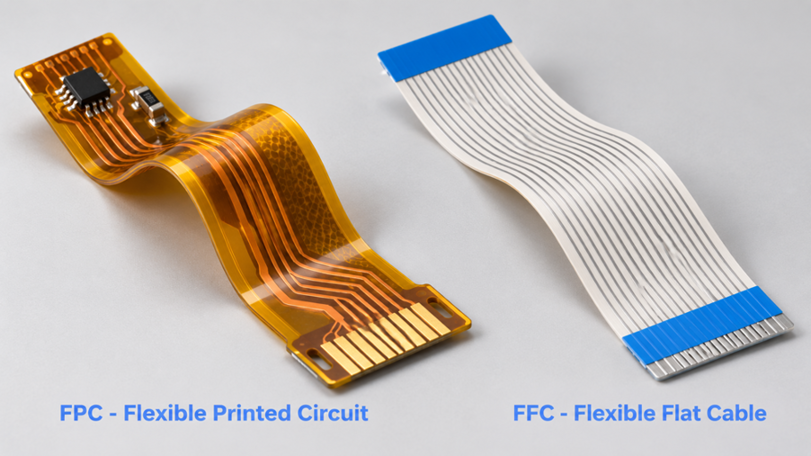
Figure 1: An FPC tail and an FFC ribbon side by side at the same scale
It also costs more, because etching and coverlay lamination are real process steps that a flat cable never needs. Once you see the two as different manufacturing routes rather than two grades of cable, the choice stops being about price alone. This guide covers how each is built, where the pitch and layer limits sit, and which one belongs in your next enclosure.
Understanding FPC and FFC in Modern Electronics
Both parts do the same job of moving signals across a hinge, so from the outside they look interchangeable. What separates them is whether the copper was etched into a circuit or simply laid down in parallel.
What Is an FPC (Flexible Printed Circuit) and How Does It Work?
FPC stands for flexible printed circuit, and it is a printed circuit board whose substrate bends. The base is polyimide film, usually 25 or 50 microns (1 or 2 mil) thick, clad with copper foil. That copper is etched into whatever pattern the design needs so that an FPC can carry a real circuit rather than only a set of wires.
Copper choice decides how many bends the part survives:
- Rolled annealed copper has an elongated grain structure that resists fatigue cracking, so it belongs in anything that flexes in service.
- Electrodeposited copper is cheaper, but its columnar grains crack sooner. That makes it fine for a part folded once during assembly and then left alone.
The coverlay replaces the solder mask on a flex circuit. It is a polyimide film with adhesive, laminated over the finished copper. Because it is a film rather than a cured liquid, it survives repeated bending. Windows are cut in it wherever a pad must be exposed, so pad openings are drawn as their own CAD layer.
What Is an FFC (Flexible Flat Cable) and Where Is It Used?
FFC stands for flexible flat cable. It is a ribbon of parallel copper conductors sealed between two PET films. The conductors are flat rolled strips rather than round wires, so the finished cable stays under about 0.3 mm (12 mil) thick. Both ends are stripped and tinned to slide into a ZIF connector.
You find FFC wherever two boards face each other and only need a bus between them. The link from a laptop's mainboard to its display panel is one common case. An FFC cannot host a component or change conductor count partway along, because every strip is identical from end to end. An FPC is a flexible circuit designed to bend. An FFC is a flat cable designed mainly to carry signals.
FPC vs FFC: Structural and Design Differences
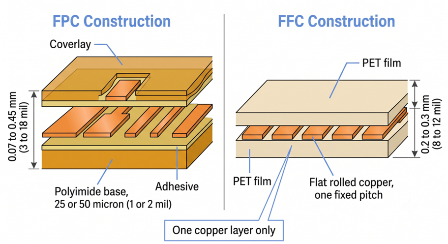
Figure 2: Cross-section comparison of an FPC stackup and an FFC laminate
The structural gap between the two technologies shows up clearly in cross-section. An FFC has one copper layer and no way to add a second, while an FPC can stack copper, adhesive, and polyimide into a four-layer sandwich.
Printed Circuit Traces vs Parallel Flat Conductors
An FPC trace is subtractive, meaning copper is etched away until only the pattern remains. An FFC conductor is additive in effect, because pre-cut copper strips are simply laid down and laminated. That one process difference decides what geometry is possible on each part.
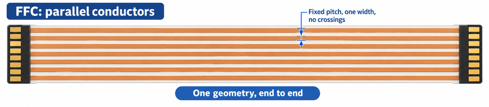
Figure 3: Top-down view of parallel FFC conductors
Etching lets a trace be any width the current needs, so a 2 mm (79 mil) power rail can sit beside a 0.1 mm (4 mil) signal. Traces can also fan out, converge, and cross on a second layer through vias. An FFC gets none of that, and its impedance is whatever the fixed strip geometry gives. That is why USB and MIPI links run on flex rather than flat cable.
| Pitch | Conductor Width | Current per Conductor | Typical Way Count | What This Fits |
| 0.30 mm (12 mil) | 0.15 mm (6 mil) | 0.2 A | 21 to 61 | Phone camera modules |
| 0.50 mm (20 mil) | 0.30 mm (12 mil) | 0.5 A | 4 to 80 | Laptop and tablet display panels |
| 1.00 mm (39 mil) | 0.60 mm (24 mil) | 1.0 A | 4 to 60 | Printers and scanners |
| 1.25 mm (49 mil) | 0.80 mm (31 mil) | 1.0 A | 2 to 40 | Industrial and automotive panels |
| 2.54 mm (100 mil) | 1.50 mm (59 mil) | 2.0 A | 2 to 26 | Legacy IDE ribbons, prototyping |
Current per conductor tracks pitch almost directly, so a 0.5 mm (20 mil) cable tops out at about 0.5 A per line. A rail above that either moves to a coarser pitch or gets doubled across two conductors.
Custom Circuit Layouts vs Standardized Cable Configurations
An FFC is a catalog part, so you choose from a list rather than draw one. Pitch, way count, length, and end type are the only variables, and the rest is fixed by the supplier. An FPC is drawn from scratch in your CAD tool. Outline, bend zones, stiffener positions, and pad geometry are all yours to define.
Customization is the whole reason an FPC costs more. Every design needs its own tooling: an etch pattern, a coverlay opening set, a profile cut, and often a stiffener press. Those setups are charged against your order, whereas an FFC supplier spreads tooling across millions of meters of identical cable. An FFC is selected from a catalog in five minutes. An FPC is designed instead, so the design time is what buys you geometry that no cable can offer.
Comparing FPC and FFC Performance and Design Capabilities
Performance here means three things: how much circuit fits, how the part survives motion, and how it joins the rest of the product. FPC wins the first and third outright, while the second depends entirely on material choice.
| Property | FFC | FPC | What It Means for Your Design |
| Conductor layers | 1 only | 1, 2, or 4 | Crossing signals need an FPC |
| Base film | PET | Polyimide, 25 or 50 micron (1 or 2 mil) | Polyimide survives reflow, PET does not |
| Finished thickness | 0.2 to 0.3 mm (8 to 12 mil) | 0.07 to 0.45 mm (3 to 18 mil) | FPC fills the gaps that a cable cannot |
| Trace geometry | One fixed pitch, one width | 3 mil (0.076 mm) minimum trace and space | Power and signal share one part |
| Components | None | SMT parts, vias, stiffeners | An FPC can be the board itself |
| Termination | ZIF connector on both ends | Solder, ZIF, or rigid flex | FPC can delete two connectors |
Everything about cost and availability favors FFC, while everything about geometry and integration favors FPC. The decision, therefore, comes down to one question: does your link need a circuit, or only a bus?
Circuit Complexity, Routing Flexibility, and Space Utilization
Layer count is the hard boundary. An FFC has exactly one conductor layer and will never have two, because lamination has no way to interconnect them. An FPC runs one, two, or four copper layers, and JLCPCB builds all three. A dense sensor head can therefore route signals over the flex's ground plane.
- An FFC needs a connector at each end, and the connector is often the larger part. A 30-way 0.5 mm (20 mil) ZIF socket takes roughly 17 mm (0.67 in) of board edge, on both boards. An FPC can be soldered directly down instead, removing two connectors and their mating tolerance from the assembly.
- An FPC folds into a Z shape or wraps around a battery, and the designer places every one of those bends. Copper can therefore be routed away from each crease. An FFC bends too, but only across its width, because a flat ribbon cannot turn a corner in a plane.
Customization, Mechanical Requirements, and Integration Potential
The bend radius sets mechanical life for flexible PCBs, and IPC-2223 gives the multipliers. A static bend is one that the part takes once at assembly, so it needs only 6 times the total thickness on a single-layer flex. Multilayer flex needs 12 times. A dynamic bend that moves in service needs 100 times or more.
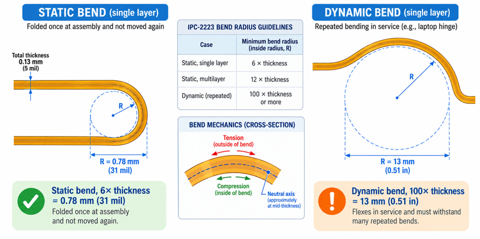
Figure 4: Static and dynamic bend radius calculated from total flex thickness
A single-layer flex on 25-micron (1 mil) polyimide with 0.5 oz copper and a coverlay lands at near 0.13 mm (5 mil) thick. Six times that gives a 0.78 mm (31 mil) static bend radius, which any fold inside a handset clears. The same part, flexing in service, needs 13 mm (0.51 in) of clearance, but that much clearance rarely exists inside a wearable.
Choosing Between FPC and FFC for Different Electronic Applications
Three questions settle most of these decisions, so the choice is rarely as close as it looks. They are whether the link carries a plain bus, whether the connectors have room, and whether anything must be mounted on the flexible part itself.
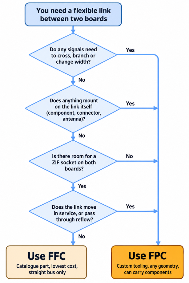
Figure 5: Decision flow for choosing between an FPC and an FFC
When FFC Is Suitable for Simple Internal Connections
FFC is the right answer when the link is a straight bus between two fixed boards, and nothing has to sit on the cable. Display panels, printer carriages, keyboard matrices, and control panel fronts all fit that description. It stays the right answer as long as four conditions hold:
- Signals run parallel end to end. No conductor crosses, branches, or changes width.
- Both ends land on a connector. A ZIF socket sits on each board, or there is room to add one.
- Current per line stays modest. A 0.5 mm (20 mil) pitch cable is limited to roughly 0.5 A per conductor.
- The cable only folds during assembly. PET handles gentle static bends, but it is not a flow-capable material.
Thirty conductors at 0.5 mm (20 mil) pitch carry the eDP pairs, backlight power, and an EDID line between a laptop mainboard and its panel. The cable folds once through the hinge channel at assembly and never moves again, so PET insulation is enough.
When FPC Is Better for Compact and Customized Electronic Designs
FPC becomes the answer the moment the link has to do more than carry a bus. That includes any part with a component soldered on it. It also covers any part that folds into a shape rather than a simple arc, and any part where two connectors will not fit. Camera modules, smartwatch antennas, and fingerprint sensors are all in that group.
PET softens well below reflow temperature, so an FFC can never pass through an oven. Polyimide retains its shape above 260 °C (500 °F). That is why an FPC can be populated on the same SMT line as your rigid boards. A flat cable has to be plugged in afterward by hand. Choose FFC when the link is a bus, and both boards have room for a socket. Choose FPC when the link is part of the circuit, because deleting two connectors often pays back the tooling charge.
Advanced Flexible Circuit Manufacturing Solutions at JLCPCB
JLCPCB builds FPC rather than FFC, which follows from what each part is. A flat cable is a commodity you buy by the reel, whereas a flexible printed circuit is fabricated to your file like any other board.
Custom FPC Fabrication for Complex Layouts and Space-Constrained Designs
JLCPCB fabricates 1-, 2-, and 4-layer polyimide flex on 25- or 50-micron (1- or 2-mil) dielectric film. Finished thickness runs from 0.07 mm to 0.45 mm (3 to 18 mil), far below the usual rigid board thickness options. Copper comes at 0.33 oz, 0.5 oz, or 1 oz, so one part can carry a power rail and fine signal routing together.
| Parameter | JLCPCB FPC Capability | What It Lets You Build |
| Layer count | 1, 2, and 4 layers | Impedance-controlled pairs over a ground plane |
| Base film | Polyimide, 25 or 50 micron (1 or 2 mil) | Flex that survives 260 C (500 F) reflow |
| Copper weight | 0.33 oz (12 micron) to 1 oz (35 micron) | Power and signal on one tail |
| Trace and space | 3 mil (0.076 mm) minimum at 0.33 oz | Fine pitch fan out in a narrow arm |
| Stiffener | PI, FR4 up to 1.6 mm (63 mil), or steel | Rigid pads for connectors and screws |
| EMI shielding film | 18 micron (0.7 mil) black film | Shielded runs without a braid |
A minimum trace and space of 3 mil (0.076 mm) is what makes an FPC worth its tooling cost. That is tight enough to fan out a 0.4 mm (16 mil) pitch camera connector directly on the flex. Etch resolution comes from photolithography, whereas an FFC conductor is cut by a slitting blade.
Reliable FPC Prototyping and Manufacturing for Product Development
Flex prototyping fails most often at the file stage, not the fab stage. A flex order needs a few things that standard PCB design rules never ask for, so leaving them out turns a two-day build into a week of review. Five steps cover what the fab needs from you.
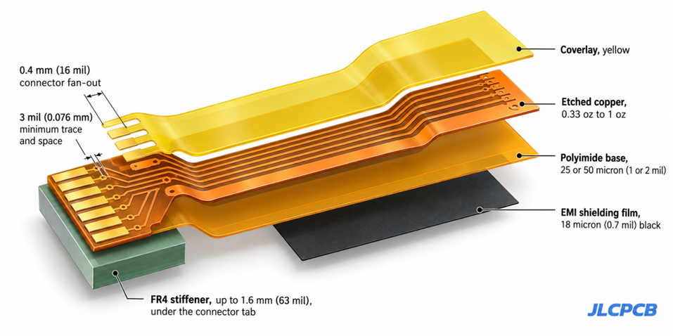
Figure 6: JLCPCB FPC build showing coverlay, stiffener, and EMI shielding film
- Set the stackup before you route: Choose layer count, polyimide thickness, and copper weight first, because bend radius follows the finished total.
- Draw the coverlay as its own layer: Mark every pad opening, and keep the coverlay edge back from any bend line.
- Keep copper out of the bend zone: Route traces perpendicular to the bend axis, and replace solid copper pours with a cross-hatch.
- Put stiffeners on a separate layer: Name the material and thickness for each, since PI, FR4, and steel are pressed differently.
- Send the outline as a closed profile: Flex is laser- or die-cut to that outline so that an open contour will stop the job.
Flex sits on the same quote page as rigid boards, so the price updates as you adjust layer count or copper weight. Parts for a populated assembly come from the same component library, so one order covers both. Order a small batch first and fold it the way the enclosure will. A bend radius that passes in CAD can still crack on the bench.
Conclusion
The FPC vs FFC question sorts itself once you stop comparing them as two kinds of cable. One is a manufactured circuit that happens to bend, and the other is a manufactured cable that happens to be flat. Every difference in cost, thickness, layer count,t, and thermal limit traces back to that. Flexible circuits are taking a larger share of the work as products get thinner, because a folded FPC removes connectors, solder joints, and board area at once. If your next link is starting to look like a small board, it probably is one, and JLCPCB builds 1, 2, and 4-layer polyimide flex straight from your Gerber files.

FAQs About FPC vs FFC
Q: Can I plug an FPC tail into an FFC connector?
Ans: Usually yes, because a ZIF connector grips on thickness and pitch rather than on material. Match the pitch, the contact side, and the insertion thickness the connector expects, which is commonly 0.3 mm (12 mil).
Q: What does FFC stand for, and how is it different from an old ribbon cable?
Ans: FFC stands for flexible flat cable. A classic ribbon cable holds round conductors in molded insulation at a 1.27 mm (50 mil) pitch, whereas an FFC uses flat, rolled copper strips laminated in a film. That is why an FFC is thinner and folds flat.
Q: How many conductors can an FFC have before I should switch to an FPC?
Ans: There is no hard limit, since 0.5 mm (20 mil) cables are made up to roughly 80 ways. The switch happens when signals stop being parallel: once two lines must cross or one needs a different width, no conductor count will help.
Q: Is an FFC ever the better choice for high current?
Ans: Yes. A 2.54 mm (100 mil) pitch FFC carries about 2 A per conductor as an off-the-shelf part, whereas pushing that current through thin flex needs wide copper and 1 oz foil, which raises cost and stiffness.
Q: Does every FPC need a stiffener?
Ans: No, only where something mechanical happens. Connector insertion areas, screw holes, and SMT pad clusters need local rigidity, while a plain routing tail does not. Adding stiffener everywhere defeats the point of using flex.

Popular Articles
• Understanding the Basics of Electronic Devices and Circuits
• Understanding Digital Circuit Timing: Setup Time, Hold Time, Contamination Delay & Clock Skew
• PCBs Explained: A Simple Guide to Printed Circuit Boards
• Guide to the Top 10 Commonly Used Electronic Components
• Digital 101: Fundamental Building Blocks of Digital Logic Design
Keep Learning
Polyimide Flex PCB: A Complete Guide for Engineers
A polyimide flex PCB can be folded about 285,000 times when the base film is 25 µm (1 mil) thick. Make that film 75 µm (3 mil), and the same MIT fold test gives up near 6,000 cycles. Bending is a strain problem, not a material problem. Copper sits above the center of the stack, so a bend forces it to stretch around the longer outer path. Figure 1: A polyimide flex circuit folded tight, with a stiffener holding the connector A thicker stack places the copper farther out, resulting in more stretch at th......
Flex PCB Bend Radius: Calculation, Minimum Radius & Design Guidelines
Flex PCB bend radius is the one dimension on an FPC that no design rule check will catch. Bend the circuit tighter than its material allows; the outer copper stretches from its elongation limit, and then it cracks. Figure 1: A flex circuit formed around a mandrel, with bend radius and stack thickness A flex circuit bends around a neutral axis near the middle of its stack. Copper below that line is squeezed, and copper above it is pulled. So the further a layer sits from the line, the harder it is to w......
Flexible Circuit Connector: Types, Features & Selection Guide
A flexible circuit connector clamps onto the bare copper at the end of a flex circuit, so nothing is soldered at that joint. The tail slides into the housing, and an actuator presses a row of spring contacts onto the pads. Every connector is built around one tail thickness. TE's 0.5 mm pitch 2328702 family expects 0.30 mm (12 mil) of flex, because the contact beams are deflected by exactly that dimension. Figure 1: Cross-section of a 0.5 mm pitch FPC connector with the tail inserted Feed it a bare sin......
FPC vs FFC: Understanding the Key Differences Between Flexible Circuit Technologies
The FPC vs FFC decision is really a question about how the copper was made. An FFC consists of flat copper strips laminated between two PET films. Every conductor runs straight from end to end at one fixed pitch, because nothing in that process can make a trace turn or branch. An FPC starts as copper-clad polyimide and is etched exactly like a rigid board. Traces can turn, taper, split onto a second layer, and land under a soldered component. The finished circuit can be as thin as 0.1 mm (4 mil). Figu......
A Comprehensive Guide to Capacitor ESR: What It Is, Good Values, and How to Measure It
Key Takeaways Definition: Capacitor ESR (equivalent series resistance) is the single resistance that represents the losses inside a real capacitor, from its electrodes, terminations, electrolyte, and dielectric. Why It Matters: Ripple current flowing through the ESR produces a ripple-voltage step on the supply rail and I²R heating in the capacitor, which limits the capacitor's ripple-current rating and service life. Conditions Matter: ESR varies with frequency, temperature, capacitance, case size, and......
Understanding IPC-6012 Standards for High-Reliability Rigid PCB Fabrication
Key Takeaways IPC-6012 vs. IPC-A-600: IPC-6012 is the binding specification, while IPC-A-600 is only for visual reference. Class 2 vs. Class 3: Class 3 requires thicker copper (25μm vs. 20μm) and zero plating voids. Coupon Verification: Quality is tested by microsectioning panel coupons after thermal stress. Upfront Callout: Specify the class on drawings upfront; boards cannot be upgraded later. IPC-6012 is the line on your fabrication drawing that decides what your supplier is allowed to ship. Most d......