A Comprehensive Guide to Capacitor ESR: What It Is, Good Values, and How to Measure It
14 min
- What Is Capacitor ESR?
- Why Does Capacitor ESR Matter?
- How Does Capacitor ESR Change with Frequency and Temperature?
- What Is a Good ESR Value for a Capacitor?
- How to Find ESR of a Capacitor from a Datasheet
- How to Measure Capacitor ESR
- What Are the Symptoms of a High-ESR Capacitor?
- Conclusion
- FAQs About Capacitor ESR
Key Takeaways
- Definition: Capacitor ESR (equivalent series resistance) is the single resistance that represents the losses inside a real capacitor, from its electrodes, terminations, electrolyte, and dielectric.
- Why It Matters: Ripple current flowing through the ESR produces a ripple-voltage step on the supply rail and I²R heating in the capacitor, which limits the capacitor's ripple-current rating and service life.
- Conditions Matter: ESR varies with frequency, temperature, capacitance, case size, and technology, so an ESR figure is meaningful only when the test frequency and temperature are stated with it.
- How to Measure: An ESR meter suits quick checks, while an LCR meter with four-wire Kelvin leads checks a part against its datasheet. A standard multimeter cannot measure ESR.
- Lower Is Not Always Better: Some linear regulators rely on the output capacitor's ESR for loop stability and specify a minimum ESR, so check the regulator datasheet before substituting a low-ESR part.
Capacitor ESR (equivalent series resistance) is the resistive component of a real capacitor's impedance, which converts ripple current into ripple voltage and heat. It is a common reason a power supply runs hot or shows more output ripple than the design predicted, even when every capacitor measures the correct capacitance.
In this guide, you will learn:
- What capacitor ESR is and where it comes from
- Why ESR sets ripple voltage, self-heating, and regulator stability
- What a good ESR value looks like for each capacitor technology
- How to find ESR on a datasheet and measure it with an ESR or LCR meter
- How to recognize the symptoms of high ESR
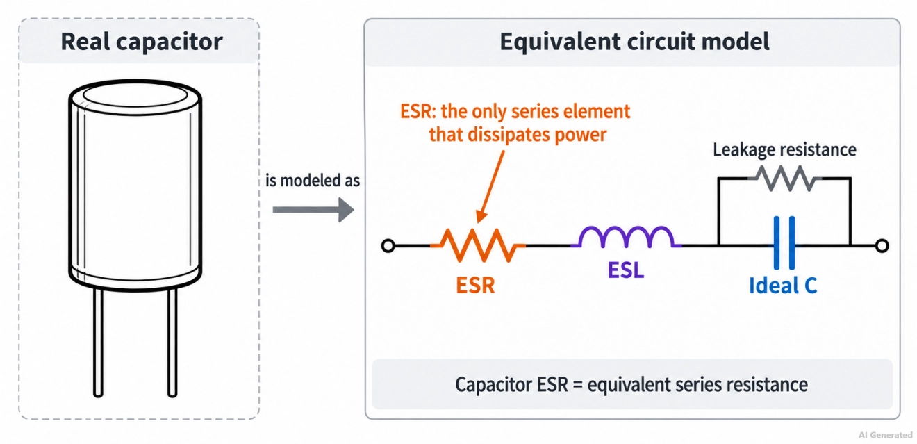
Figure: Ideal capacitor ESR equivalent circuit with ESR and ESL in series
What Is Capacitor ESR?
A real capacitor can be modeled as an ideal capacitance in series with equivalent series resistance (ESR) and equivalent series inductance (ESL), with leakage resistance represented in parallel with the capacitor. ESR is expressed in ohms or milliohms and represents the resistive losses in the capacitor's series path.
ESR comes from several sources:
- Electrode and termination resistance: Metal foils, internal tabs, electrodes, and terminals all contribute to the capacitor's series resistance.
- Electrolyte resistance: In wet aluminum electrolytic capacitors, the electrolyte's ionic resistance can be a major contributor to ESR, and its conductivity changes significantly with temperature.
- Dielectric loss: Energy is also dissipated through dielectric losses, which contribute to the capacitor's overall ESR and dissipation factor.
Capacitor ESR vs. ESL, Impedance, and Dissipation Factor
Each of these datasheet terms describes a different part of the capacitor's behavior:
| Parameter | What It Represents | Unit | Where It Dominates |
|---|---|---|---|
| ESR | Resistive losses in the series path | Ω or mΩ | At SRF,capacitive and inductive reactances cancel, so the impedance magnitude reaches a minimum that is approximately determined by the resistive losses, including ESR. |
| ESL | Inductance of the terminals and internal structure | nH | Above the self-resonant frequency |
| Capacitive reactance (Xc) | Ideal capacitance, Xc = 1 / (2πfC) | Ω | Below the self-resonant frequency |
| Impedance (Z) | Total opposition to AC: ESR, Xc, and the ESL reactance combined | Ω | All frequencies |
| Dissipation factor (DF, tan δ) | Ratio of loss to reactance, DF = ESR / Xc | Dimensionless | Quoted at low frequency, often 120 Hz |
Why Does Capacitor ESR Matter?
Capacitor ESR matters because every ampere of ripple current that flows through it produces a voltage drop and heat. In a power supply, ESR contributes to the output ripple, limits the ripple current the capacitor can carry, and can affect regulator stability.
How ESR Affects Ripple Voltage
In a buck converter operating in continuous conduction mode (CCM), the capacitor's ESR produces a voltage-ripple component approximately equal to the capacitor ripple current multiplied by the ESR.
A simplified estimate of the total output-voltage ripple is:
ΔV ≈ ΔI × ESR + ΔI / (8 × f × C)
where:
- ΔI is the inductor ripple current, peak to peak
- f is the switching frequency
- C is the output capacitance
For example: Assume a 100 µF output capacitor in a 100 kHz buck converter with 0.5 A peak-to-peak ripple current. The capacitive ripple term is about 6.25 mV. Using example ESR values measured at the same 100 kHz frequency:
| Output Capacitor (100 µF) | ESR at 100 kHz | ESR Ripple Term (0.5 A) |
|---|---|---|
| Wet aluminum electrolytic, low-ESR type | 300 mΩ | 150 mV |
| MnO2 tantalum | 100 mΩ | 50 mV |
| Polymer aluminum | 10 mΩ | 5 mV |
This example shows how a higher ESR can make the ESR component of output ripple much larger than the capacitive component.
Adding low-ESR ceramic or polymer capacitors in parallel can reduce the effective ESR and impedance of the output capacitor bank, provided their frequency characteristics and PCB layout are suitable for the application.
Self-Heating and the Ripple Current Rating
Ripple current also dissipates power inside the capacitor:
P = I²rms × ESR
A 1 A rms ripple current dissipates 100 mW in a 100 mΩ ESR, but only 10 mW in a 10 mΩ ESR. The ripple current rating on a datasheet is derived from the permissible internal temperature rise at a stated frequency and ambient temperature. For wet aluminum electrolytic capacitors, higher internal temperature also shortens service life.
Can Capacitor ESR Be Too Low?
Yes, in some linear regulators. Some LDO regulators, especially older designs with a PNP pass transistor, use the zero formed by the output capacitor's ESR to keep the control loop stable. These regulators specify both a minimum and a maximum ESR.
Replacing a tantalum output capacitor with a very low-ESR ceramic capacitor in such a design can make the regulator oscillate. Check the regulator datasheet for its stable ESR range before substituting a lower-ESR part.
How Does Capacitor ESR Change with Frequency and Temperature?
Capacitor ESR is not a fixed value. Typically, ESR varies with frequency, and its frequency characteristic depends on the capacitor technology and construction.
It generally decreases as frequency approaches the self-resonant frequency, and in wet aluminum electrolytic capacitors, it rises sharply as temperature decreases.
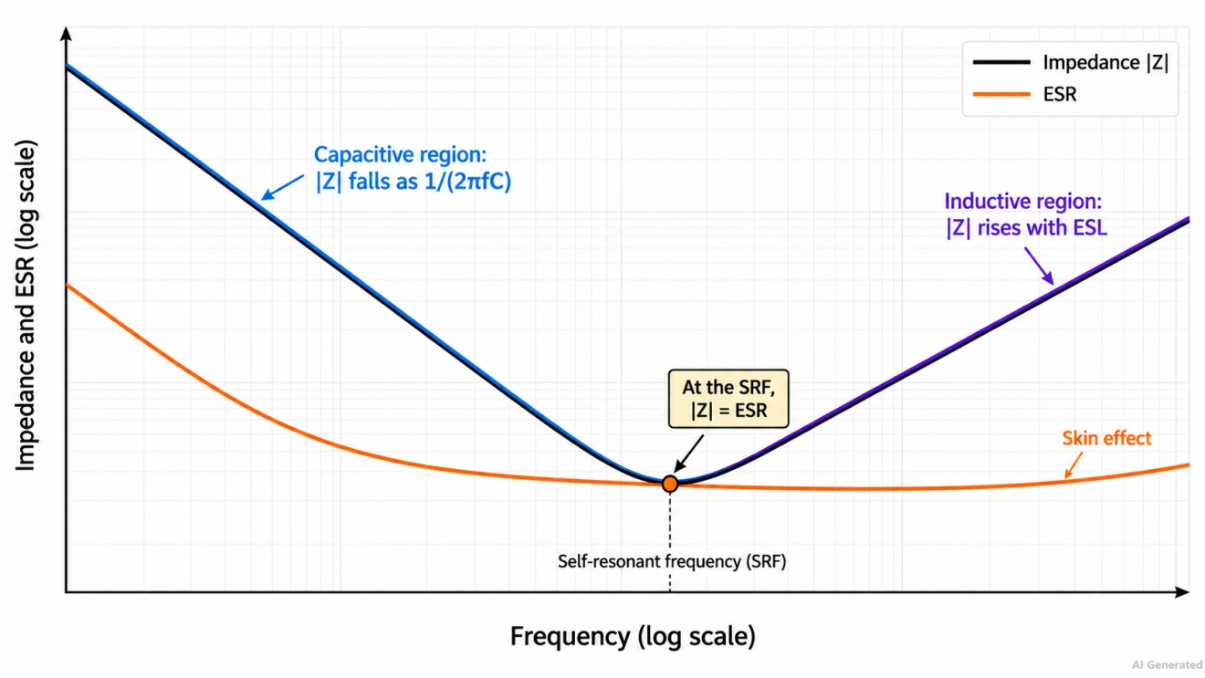
Figure: Capacitor ESR Chart: Capacitor ESR and impedance versus frequency
- Low frequencies: Dielectric losses dominate, so ESR is typically highest.
- Mid frequencies: Electrolyte and construction effects set the ESR, and the curve flattens.
- High frequencies: Electrode and termination resistance dominates, and the skin effect can raise ESR again at very high frequencies.
- Self-resonant frequency: At the self-resonant frequency (SRF), capacitive and inductive reactances cancel out, leaving the impedance equal to the ESR.
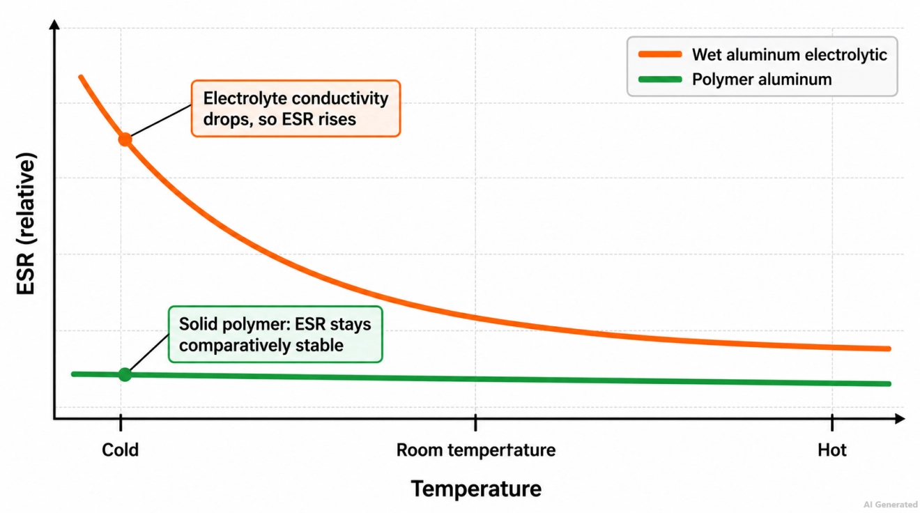
Figure: Capacitor ESR Chart: Capacitor ESR vs. temperature for a wet aluminum electrolytic and a polymer aluminum capacitor.
Temperature affects technologies differently:
- Wet aluminum electrolytic: ESR decreases with temperature and increases at low temperatures due to reduced electrolyte conductivity. Many datasheets state this as a maximum impedance ratio, such as Z(−25 °C) / Z(+20 °C) at 120 Hz.
- Polymer aluminum and polymer tantalum: The solid conductive polymer keeps ESR comparatively stable across the rated temperature range.
- Ceramic (MLCC): ESR stays low with temperature, although Class II dielectrics such as X7R have a higher dissipation factor than Class I (C0G) dielectrics, especially at low frequency.
Selection rule: Compare ESR values only at the same frequency and temperature, and use the frequency at which your circuit operates.
What Is a Good ESR Value for a Capacitor?
A good ESR value is one at or below the datasheet maximum for that part, at the stated frequency and temperature. No single threshold applies to every capacitor, because ESR depends on technology, capacitance, voltage rating, and case size.
The technology sets the order of magnitude. This comparison uses capacitor types of the same rating, 100 µF and 10 V, with each part's datasheet maximum at 100 kHz and room temperature (20 °C or 25 °C, depending on the manufacturer).
The case sizes also differ slightly; see our guide to SMD capacitor sizes for package dimensions.
Note: The following capacitor ESR value table compares example ESR or impedance values across common capacitor technologies.
| Technology | Example Part | Case Size | Specified ESR or Impedance at 100 kHz | Rated Ripple Current at 100 kHz |
|---|---|---|---|---|
| Wet aluminum electrolytic, low-impedance series | Rubycon 10ZL100MEFC5X11 (ZL) | 5 × 11 mm radial | 300 mΩ (impedance) | 250 mA at 105 °C |
| MnO2 tantalum, low-ESR series | KEMET T495D107K010ATE100 | 7.3 × 4.3 × 2.8 mm (D, 7343-31) | 100 mΩ | 1,225 mA at 25 °C |
| Polymer tantalum | KEMET T520D107M010ATE018 | 7.3 × 4.3 × 2.8 mm (D, 7343-31) | 18 mΩ | 3,500 mA at 45 °C |
| Polymer aluminum | KEMET A700X107M010ATE010 | 7.3 × 4.3 × 4.0 mm (X, 7343-43) | 10 mΩ | 4,700 mA |
Table: Capacitor ESR table
The ripple current ratings follow the ESR: the polymer parts are rated for many times the ripple current of the wet aluminum part.
Manufacturers state these ratings at different ambient temperatures, so apply each datasheet's temperature correction before comparing them.
Ceramic (MLCC) capacitors typically have the lowest ESR among common technologies, often a few milliohms at their self-resonant frequency. That low ESR, combined with low ESL, is why MLCCs are the standard choice for decoupling capacitors close to IC power pins.
Selection rule: Choose the technology whose datasheet ESR, at your operating frequency and lowest operating temperature, keeps both the ripple voltage and the ripple current within your limits.
Compare polymer, tantalum, and MLCC options, along with their package information, before finalizing your BOM and SMT assembly order.
How to Find ESR of a Capacitor from a Datasheet
Where do I find ESR on a datasheet?
Capacitor ESR appears on a datasheet as an ESR value, usually at 100 kHz and 20 °C or 25 °C, as a maximum impedance at 100 kHz, or indirectly as a dissipation factor (tan δ), usually at 120 Hz or 100 Hz. When only tan δ is given, you can calculate ESR from it.
Polymer and tantalum series usually list ESR at 100 kHz. Low-impedance aluminum series often list maximum impedance at 100 kHz, which approximates ESR when the capacitive reactance at that frequency is small.
General-purpose aluminum electrolytic series often list only tan δ and a ripple current rating.
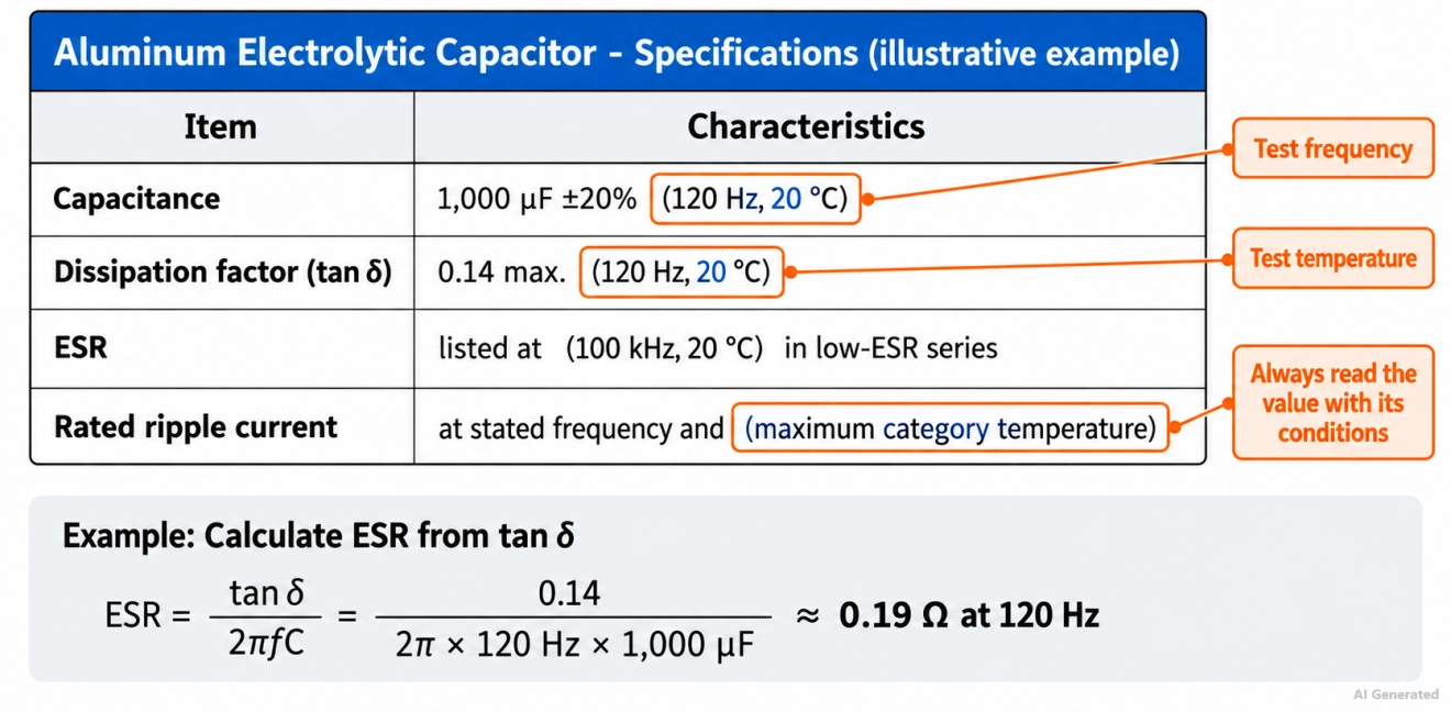
Figure: Datasheet excerpt with ESR, dissipation factor, and ripple current test conditions
To convert a dissipation factor to ESR, use:
ESR = tan δ / (2πfC)
For example, a 1,000 µF capacitor with a maximum tan δ of 0.14 at 120 Hz has a capacitive reactance of about 1.33 Ω at 120 Hz. Its maximum ESR at 120 Hz is therefore about 0.14 × 1.33 Ω, or 0.19 Ω. At switching-converter frequencies, the ESR of the same part is typically lower, so use the 100 kHz value or the manufacturer's frequency correction data where available.
How to Measure Capacitor ESR
Capacitor ESR is measured by driving a small AC test signal through the capacitor at a frequency where its reactance is low, then measuring the resulting voltage and current.
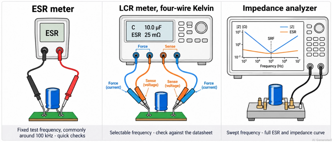
Figure: Three ways to measure capacitor ESR: ESR meter, four-wire Kelvin LCR meter, and impedance analyzer.
| Method | Test Frequency | In-Circuit Use | Best For |
|---|---|---|---|
| Handheld ESR meter | Fixed, commonly around 100 kHz | Often possible, because the test voltage is too low to turn on semiconductor junctions | Quick health checks of electrolytic capacitors |
| LCR meter with four-wire Kelvin leads | Selectable, such as 120 Hz, 1 kHz, 10 kHz, or 100 kHz | Out of circuit preferred | Checking a part against its datasheet at the specified frequency |
| Impedance analyzer | Swept across a wide frequency range | Out of circuit | Full ESR and impedance curves, including the self-resonant frequency |
| Digital multimeter | DC only | Not applicable | Not suitable: it measures DC resistance or capacitance, not ESR |
On an LCR meter, use series mode (Cs–Rs) for large capacitances, where the impedance is low. The four-wire Kelvin connection separates the current and voltage leads, so lead and contact resistance do not add to a milliohm reading.
How to Check ESR of Capacitors with an ESR Meter
To check a capacitor with a handheld ESR meter:
- Remove power and discharge the capacitor, then confirm with a multimeter that the voltage across it is close to zero.
- Short the meter probes together and zero the reading to remove the probe resistance.
- Connect the probes across the capacitor terminals and read the ESR.
- Compare the reading with the datasheet maximum at the same frequency, or with a new capacitor of the same part number, measured the same way.
- If an in-circuit reading looks low but the circuit still shows symptoms, remove the capacitor and measure it again, because parallel capacitors on the board lower the reading.
Note: An ESR meter can be damaged if it is connected to a charged capacitor or a powered circuit.
What Are the Symptoms of a High-ESR Capacitor?
How do I know my capacitor has high ESR?
High capacitor ESR most often appears in aging wet aluminum electrolytic capacitors. The capacitance can still be measured within tolerance, even as the ESR has risen enough to increase ripple, raise the capacitor temperature, and destabilize the power supply.
The liquid electrolyte is gradually lost through the seal by evaporation and diffusion. High temperature and ripple-current heating accelerate that loss, which raises the ESR.
Common symptoms include:
- Increased ripple and noise: The supply rail shows higher ripple than when the board was new.
- A warm capacitor: The capacitor runs noticeably hotter than it did when new, or hotter than the same part on a known-good board.
- Unstable power supply behavior: A switching supply fails to start, restarts repeatedly, or drops out under load.
- Physical damage: A bulging vent or electrolyte leakage is late-stage evidence, and many failing capacitors show no visible change.
When to Replace a High-ESR Capacitor
Many aluminum electrolytic capacitor datasheets specify endurance limits, such as a capacitance change within ±20% and a tan δ no more than 200% of its initial specified value. Limits vary by manufacturer, so always check your part’s datasheet. At a fixed frequency and capacitance, ESR is directly proportional to tan δ.
When a capacitor measures well above its datasheet maximum, or clearly higher than a new part measured the same way, replace it with a part whose ESR is at or below, and whose ripple current rating is at or above, the original part's datasheet values; on an LDO output, stay within the regulator's stable ESR range.
Conclusion
Capacitor ESR is the series resistance that turns ripple current into ripple voltage and heat, so it matters as much as capacitance in any power circuit. Compare ESR only at the same frequency and temperature, choose a part whose datasheet ESR meets your ripple, heating, and stability limits, and measure with an ESR or LCR meter rather than a multimeter.
Checking ESR early helps keep ripple low, capacitors cool, and power supplies reliable. Once your design is ready, upload your files to JLCPCB and get an instant quote for PCB fabrication and assembly.
FAQs About Capacitor ESR
Q: Is a Capacitor's ESR the Same as Its Impedance?
No. ESR is only the resistive part of impedance. Impedance also includes capacitive reactance and ESL, and it equals the ESR at the self-resonant frequency.
Q: Can You Measure Capacitor ESR with a Multimeter?
No. A standard multimeter measures DC resistance or capacitance. ESR must be measured with an AC test signal, using an ESR meter, an LCR meter, or an impedance analyzer.
Q: Do Ceramic Capacitors Have ESR?
Yes. Ceramic capacitors have ESR, but it is typically the lowest of the common technologies, often a few milliohms near their self-resonant frequency.
Q: What Does "Low ESR" Mean on a Capacitor?
It means the series is designed and specified for low ESR and high ripple current, with ESR (impedance) listed at 100 kHz. Compare the actual values, since "low ESR" is not a standardized threshold.
Q: Can I Replace a Capacitor with a Lower-ESR Type?
Usually, yes for filtering and decoupling, provided the capacitance, voltage, and ripple current ratings fit. On an LDO output, check the regulator datasheet first, because some LDOs require a minimum ESR for stability.
Popular Articles
• Understanding the Basics of Electronic Devices and Circuits
• Understanding Digital Circuit Timing: Setup Time, Hold Time, Contamination Delay & Clock Skew
• PCBs Explained: A Simple Guide to Printed Circuit Boards
• Guide to the Top 10 Commonly Used Electronic Components
• Digital 101: Fundamental Building Blocks of Digital Logic Design
Keep Learning
A Beginner's Guide to Printed Circuit Board Repair: Common Issues, Methods, and Solutions
Key Takeaways Understand PCB structures, components, and common failure causes to identify repair challenges effectively. Follow a systematic PCB repair process, from fault diagnosis and component replacement to testing and verification. Know when PCB repair is practical and when remanufacturing a new PCB provides a more reliable solution. A printed circuit board (PCB) is a critical part of almost every electronic device. When a board fails, the problem may come from damaged components, broken copper ......
The Hardware Development Process: From Concept to a Finished Electronic Product
Key Takeaways A structured hardware development process turns concepts into functional products through key development stages. Proper PCB design balances performance, manufacturability, and reliability. Early manufacturing considerations help reduce risks and improve prototype success. A reliable PCB partner enables smoother transitions from design to production. Every electronic device you have ever used began as a single idea. A desk lamp that brightens with a tap, a wireless earbud, a controller i......
Demystifying Bare PCB Quality for Reliability-Critical Applications
Key Takeaways Early Defect Catching: Catching faults at the bare board stage costs only the PCB, avoiding wasted components and rework later. Perfboard Risks: Zero PCBs lack reference planes and plated holes, causing signal noise above 10–20 MHz and pad lifting. Critical Material Specs: Reliability depends on hole barrel copper (20–25 µm), Tg, Td, and CTI ratings matching your operating environment. Finish & Shelf Life: HASL and ENIG last ~12 months, while OSP and Immersion Silver/Tin expire in ~6 mon......
A Comprehensive Guide to Capacitor ESR: What It Is, Good Values, and How to Measure It
Key Takeaways Definition: Capacitor ESR (equivalent series resistance) is the single resistance that represents the losses inside a real capacitor, from its electrodes, terminations, electrolyte, and dielectric. Why It Matters: Ripple current flowing through the ESR produces a ripple-voltage step on the supply rail and I²R heating in the capacitor, which limits the capacitor's ripple-current rating and service life. Conditions Matter: ESR varies with frequency, temperature, capacitance, case size, and......
Understanding IPC-6012 Standards for High-Reliability Rigid PCB Fabrication
Key Takeaways IPC-6012 vs. IPC-A-600: IPC-6012 is the binding specification, while IPC-A-600 is only for visual reference. Class 2 vs. Class 3: Class 3 requires thicker copper (25μm vs. 20μm) and zero plating voids. Coupon Verification: Quality is tested by microsectioning panel coupons after thermal stress. Upfront Callout: Specify the class on drawings upfront; boards cannot be upgraded later. IPC-6012 is the line on your fabrication drawing that decides what your supplier is allowed to ship. Most d......
Mastering PCB Plating Types and Process Control in High-Yield Fabrication
Key Takeaways Two-Step Plating: Chemical seed layer comes first, electrolytic copper adds structural strength. Process Choice: Pattern plating enables fine tracks; panel plating suits heavy copper. Via Integrity: Keep aspect ratio ≤ 10:1 to prevent thinnest-point barrel cracking. Surface Finishes: Use ENIG for flat BGA pads and hard gold for high-wear contacts. IPC Standards: Class 2 mandates 20μm copper wall thickness; Class 3 requires 25μm with zero voids. PCB plating turns a stack of drilled lamina......