Flexible Circuit Connector: Types, Features & Selection Guide
16 min
- Understanding Flexible Circuit Connectors and Their Role in FPC Systems
- Types and Key Features of Flexible Circuit Connectors
- Key Specifications to Consider When Choosing an FPC Connector
- How to Match a Flexible Circuit Connector with Your FPC Design
- JLCPCB Capabilities for FPC Connector-Ready Flexible Circuits
- Flexible Circuit Connector Applications in Modern Electronics
- Conclusion
- Frequently Asked Questions About Flexible Circuit Connectors
A flexible circuit connector clamps onto the bare copper at the end of a flex circuit, so nothing is soldered at that joint. The tail slides into the housing, and an actuator presses a row of spring contacts onto the pads. Every connector is built around one tail thickness. TE's 0.5 mm pitch 2328702 family expects 0.30 mm (12 mil) of flex, because the contact beams are deflected by exactly that dimension.
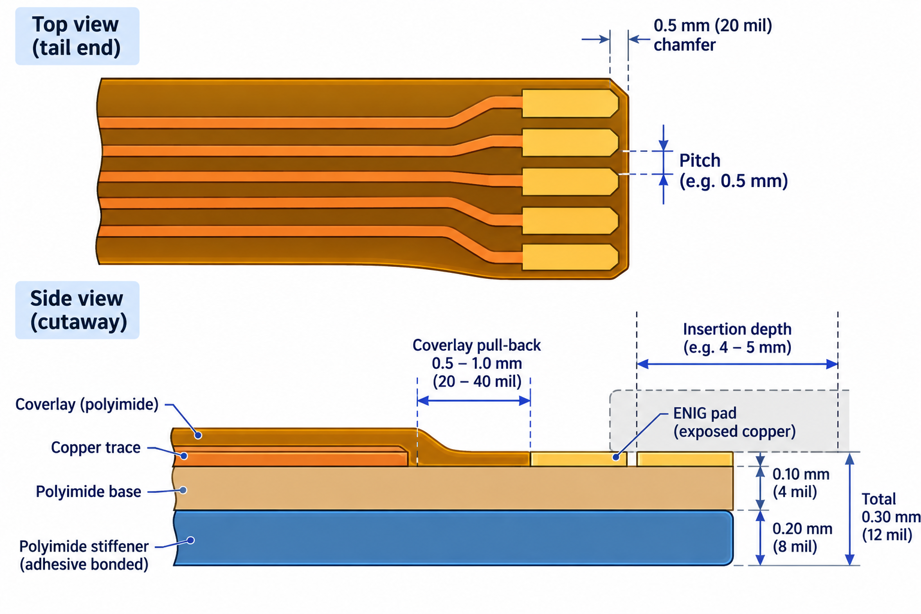
Figure 1: Cross-section of a 0.5 mm pitch FPC connector with the tail inserted
Feed it a bare single-layer flex at 0.10 mm (4 mil), and the beams barely move. Contact force collapses, so the link reads as intermittent rather than open. Go thicker, and the actuator will not latch. The connector sets that number, but your stiffener has to deliver it. This guide covers the connector types, the specifications that separate them, and the tail drawing your fabricator needs.
Understanding Flexible Circuit Connectors and Their Role in FPC Systems
A flex joint carries no solder, so the contact force has to be mechanical. The connector supplies that force, and your tail has to be built to suit it.
What Is a Flexible Circuit Connector and How Does It Work?
A flexible circuit connector is a surface-mount receptacle that grips the bare copper fingers at the end of a flexible printed circuit. Once the tail is in and the actuator closes, spring beams press onto the pads. Contact force is what makes that interface electrical. Each beam deflects by a fixed amount when the lock closes, and that deflection sets the force on the pad. Zero insertion force, or ZIF, keeps the beams clear until the actuator moves.
Why FPC Connectors Are Essential for Compact Electronic Devices
Soldering a flex tail straight to the board works, but it fixes the assembly order. A connector separates the two, so a display module can be fitted after test and a damaged flex swapped on its own. Molex's LA75 series stands 0.75 mm (30 mil) above the board, thin enough to sit under a phone display stack. Height matters because the connector, not the flex, sets the minimum gap between board and case. Solder makes a stronger joint. A connector makes the serviceable one, so in a stacked product, it usually wins.
Types and Key Features of Flexible Circuit Connectors
Three choices separate one FPC connector from another. Pitch, actuator style, and contact face decide almost everything, because those three set the mating geometry.
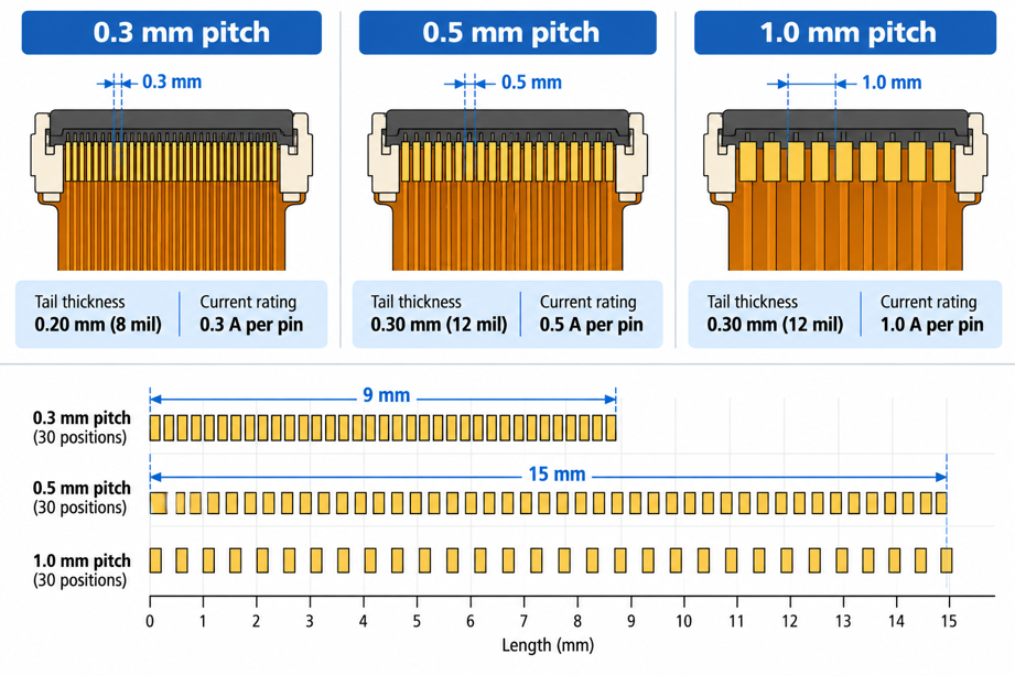
Figure 2: FPC connector pitch comparison at the same scale
FPC Connector Types by Pitch, Contact Orientation, and Mounting Direction
Pitch is the centreline spacing between contacts, and everything else scales with it. Molex's Easy-On family spans 0.20 to 2.00 mm (8 to 79 mil) across 2 to 96 circuits, while TE publishes standard ranges from 0.25 to 1.25 mm.
| Pitch | Typical Positions | FPC Tail Thickness | Max Current per Contact | What It Means for Your Design |
| 0.3 mm (12 mil) | 15 to 61 | 0.20 mm (8 mil) | 0.3 A | Signals only, on a tail built thinner than usual |
| 0.5 mm (20 mil) | 6 to 50 | 0.30 mm (12 mil) | 0.5 A | The default pitch, with the widest choice of styles |
| 1.0 mm (39 mil) | 3 to 30 | 0.30 mm (12 mil) | 1.0 A | Power rails and low pin counts, in surface mount or through-hole |
Current per contact falls with pitch. A 0.3 mm part delivers 0.3 A per pin, whereas a 1.0 mm part delivers 1.0 A per pin. The mounting direction determines where the flex goes next. A right-angle part lays the tail flat along the board. A vertical part like TE's 1734248 series takes it from above, so the flex needs clearance overhead.
Flip-Lock, Slider, and Other Actuator Mechanisms
Four actuator styles cover most of the market. They differ in where the moving part sits and how each one grips once closed.
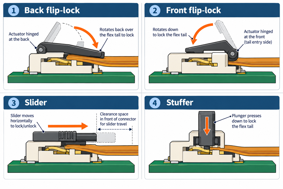
Figure 3: The four FPC connector actuator mechanisms
- Back flip-lock: the actuator hinges behind the housing and rotates back over the tail.
- Front flip-lock: the actuator hinges at the tail entry and folds down onto it.
- Slider: a bar pushes in horizontally, in the plane of the board, instead of rotating.
- Stuffer: a plunger presses straight down and then stays there as the lock.
Back flip-lock parts keep the moving piece clear of the tail entry, so you can hold the flex and close the lock at the same time. TE uses it across its 0.25 mm range, and Hirose's FH35C does the same at 0.3 mm pitch. Front flip-lock reverses that hinge, which shortens the connector but costs finger access.
Top-Contact, Bottom-Contact, and Dual-Contact Configurations
The contact position indicates which face of the tail carries the exposed pads. Getting it backward is the most common way a finished flex fails at first fit.
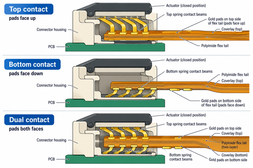
Figure 4: Top, bottom, and dual contact cross-sections
- Top contact: the beams press down from above, so the pads face up.
- Bottom contact: the beams sit in the floor of the housing, so the pads face down.
- Dual contact: beams on both faces, so the tail needs pads on both sides.
Top- and bottom-contact parts are electrically equivalent, and fine-pitch families lean towards bottom contact. TE's 0.25 mm range is bottom contact only. What changes is whether your flex has to twist before it enters, because a twist inside a 2 mm (79 mil) gap becomes a fold that cracks. Dual contact doubles the number of contact points and retention. TE's 2328702 family has a 0.30 mm (12 mil) tail on both sides at a 0.5 mm pitch.
Key Specifications to Consider When Choosing an FPC Connector
Five numbers decide whether a connector and a flex will mate: pitch, position count, tail thickness, current per contact, and temperature. All five sit on the first page, so selection is mostly reading.
Connector Pitch, Pin Count, and Contact Configuration
Work through these three in order, because each one narrows what is left.
- Pitch: the centreline spacing, set by how many signals must cross a given width.
- Pin count: the number of positions, set by signals, plus returns, power, and spares.
- Contact configuration: top, bottom, or dual, set by which face of the tail carries copper.
Thirty circuits at 0.5 mm pitch need 15 mm (590 mil) of contact span, and the same thirty at 0.3 mm need 9 mm (354 mil). If your tail has 11 mm (433 mil) of clear width, that comparison has chosen the pitch. Pin count is rarely the signal count alone, because ground returns push it up, and positions come in steps rather than continuously. Contact configuration then falls out of your stackup, since a single-layer tail rules out dual-contact parts.
FPC Thickness, Insertion Direction, and Locking Mechanism
Tail thickness is a specification you design to, because the beam deflection is built around one figure. A 0.5 mm pitch connector expects 0.30 mm (12 mil), and a 0.3 mm pitch connector expects 0.20 mm (8 mil). Tolerances are quoted near ±0.05 mm (2 mil).
Insertion direction follows the mounting style rather than the family. A right-angle housing takes the tail in along the board, and a vertical housing takes it from above, so the bend position changes with it. Locking splits in two: ZIF parts open the contacts before the tail arrives, while low insertion force parts let the tail wipe past the beams.
Electrical, Mechanical, and Environmental Requirements
Current per contact is the limit that bites first. TE rates its 1.0 mm 1734248 parts at 1 A and its 0.5 mm parts at 0.5 A. A 1.5 A rail on a fine-pitch tail therefore splits across three or four paralleled contacts.
Durability is where flex connectors differ from board-to-board parts. Amphenol, GCT, and Molex all quote 20 mating cycles on their 0.5 mm ZIF families, tested to EIA-364-09, because the beams wipe on plated copper. Operating temperature for the TE parts runs from -40 to +85 C, though some families start at -20 C. Current per contact determines how many pins your power rail needs. Durability and temperature decide whether the connector survives where the product lives.
How to Match a Flexible Circuit Connector with Your FPC Design
A connector datasheet hands you the dimensions your flex has to hit. Matching turns those numbers into a tail drawing, a stiffener callout, and a pad layout.
Matching Connector Specifications with FPC Dimensions and Layout
Tail width comes from the connector, because contact span is pitch times positions, and the housing adds an ear at each end. The recommended FPC drawing gives the width and insertion depth to cut to, so treat it like any other of your PCB design rules.
| Design Requirement | Connector Choice | Why It Works | What It Means for Your Flex |
| Over 30 signals in under 12 mm (472 mil) | 0.3 mm pitch, dual contact | 30 positions span only 9 mm (354 mil) | A two-layer tail finished at 0.20 mm (8 mil) |
| A rail drawing more than 0.5 A | 1.0 mm pitch, ZIF | Rated 1 A per contact | A wider tail, or paralleled contacts on one rail |
| Tail must exit flat under a module | Right-angle housing | The tail leaves the board plane | No bend in the first few mm of flex |
| Module replaced during service life | Back flip-lock, dual contact | Higher retention, entry stays clear | A stiffener plus exposed pads on both faces |
Designing FPC Contacts, Stiffeners, and Exposed Pads for Reliable Connection
Coverlay stops short of the tail end, leaving a window of bare copper finished with ENIG. The pads are plated rather than tinned, because a solder bump would sit proud and the actuator would ride up on it instead of closing flat.
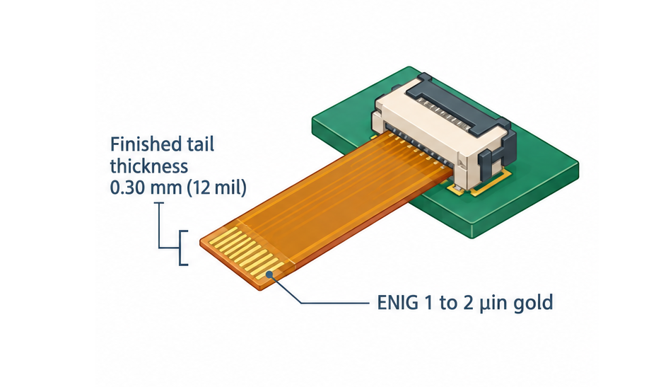
Figure 5: FPC tail construction and finished thickness
A single-layer flex on 25 µm (1 mil) polyimide with 12 µm copper finishes near 0.10 mm (4 mil). That is a third of what a 0.5-mm-pitch connector requires. Bond a 0.2 mm (8 mil) polyimide stiffener under the tail, and the stack reaches roughly 0.30 mm (12 mil). The stiffener has to cover the full insertion depth and a little beyond, so the tail stays rigid where the beams land. Chamfer the leading corners by about 0.5 mm (20 mil) so they do not catch the housing ears.
Preventing Common Connection and Assembly Problems
- Putting the pads on the wrong face survives design review, because the flex looks correct on its own and only fails when someone tries to seat it. A bottom-contact connector needs pads underneath, and flipping the tail to suit puts a permanent twist on the flex.
- Leaving the stiffener off the tail gives a joint that works on the bench and drops out under vibration. A 0.10 mm (4 mil) tail in a 0.30 mm (12 mil) connector still touches, so continuity passes while the beams sit almost undeflected.
- Giving assembly no insertion reference leaves the operator guessing how far the tail goes. Mark the insertion depth beside the footprint on your PCB silkscreen layer, outside the connector outline, so the marks survive placement.
JLCPCB Capabilities for FPC Connector-Ready Flexible Circuits
Every number above lands on the fabrication side as a material choice. Layer count, base thickness, stiffener, and coverlay are what turn a datasheet into a flex you can plug in.
Flexible PCB Manufacturing with Multiple Layer, Thickness, and Material Options
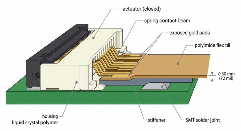
Figure 6: JLCPCB flex build under a connector tail
JLCPCB builds flexible circuits in 1 to 4 layers on polyimide. That covers the single-layer tail for a bottom-contact part and the two-layer tail for dual-contact needs. Base dielectric comes in 25 µm (1 mil) and 50 µm (2 mil), so the stiffener makes up the difference to the rated thickness.
| Parameter | Options at JLCPCB | What It Means for a Connector Tail |
| Layer count | 1 to 4 layers | Dual contact tails need two layers as a minimum |
| Base dielectric | 25 µm (1 mil), 50 µm (2 mil) | Sets how much stiffener reaches 0.30 mm (12 mil) |
| Copper weight | 12 µm (1/3 oz), 18 µm (0.5 oz), 35 µm (1 oz) | Heavier copper carries more current into each contact |
| Minimum trace and space | 0.076 mm (3 mil) at 1/3 oz, 0.10 mm (4 mil) at 1 oz | Decides whether a 0.3 mm pitch fan-out fits |
| Surface finish | ENIG, 1 or 2 µin gold | Flat-plate pads, the contact beams can wipe on |
Copper weight quietly limits pitch, since 1 oz needs 0.10 mm (4 mil) traces, where 1/3 oz gets down to 0.076 mm (3 mil).
Precision Contact, Stiffener, and Coverlay Fabrication for Connector Applications
Stiffeners are ordered as a separate layer, with a material and a thickness. Polyimide runs 0.1 to 0.25 mm (4 to 10 mil) and suits a connector tail. FR4 from 0.1 to 1.6 mm (4 to 63 mil) belongs under component areas, just as board thickness is chosen on a rigid board. Stainless steel at 0.1 to 0.3 mm (4 to 12 mil) suits a tail that gets handled repeatedly. Coverlay registration decides whether the pads sit where the beams expect them. The window is cut and laminated rather than imaged like a solder mask, so the pull-back needs real tolerance. IPC-2223 covers this class of flex detail.
Rapid FPC Prototyping and Assembly for Connector-Based Electronic Products
Flex tails are worth prototyping before the enclosure is final, because insertion depth and bend position are easier to check in your hand than in CAD. The JLCPCB flexible PCB service builds flex in about 4 to 5 days, so a second revision fits the same week.
A 0.3 mm pitch connector is not a part most people want to hand-solder. Ordering it through the JLCPCB parts library with SMT assembly puts it on the board under a proper reflow profile. You then insert a flex instead of reworking a 51-position housing. Prototyping the flex proves the drawing. Assembling the connector proves the footprint, and those are two different failures.
Flexible Circuit Connector Applications in Modern Electronics
Pitch, height, and contact style get chosen differently in a phone than in a vehicle. What changes between them is which constraint runs out first.
Consumer Electronics and Portable Devices
Phones and tablets drive the fine-pitch end, where a display module needs 30 or more signals crossing a fold in under 10 mm (394 mil). Molex's LA75 fits that many circuits into a 9 mm (354 mil) body with a 0.75 mm (30 mil) pitch. Laptop lids and folding hinges add a second demand, because the flex moves every time the product opens. The connector itself does not flex, so the stiffener has to end where the dynamic bend begins.
Automotive, Medical, Industrial, and Communication Equipment
Temperature runs out first in a vehicle, where the TE families above are rated -40 to +85 C and some start only at -20 C. Vibration pushes the choice towards dual contact and a back flip-lock, since retention comes from beams gripping both faces. Medical and industrial equipment cares more about serviceability, and 20 mating cycles are plenty for a sensor head unplugged at service intervals. Communication hardware tends to use 1.0 mm pitch on power-carrying flex, where 1 A per contact matters more than density.
High-Density and Space-Constrained Electronic Systems
Wearables and camera modules sit where pitch stops shrinking usefully. TE's 0.25 mm range uses bottom contacts, a back flip-lock, and a slanted insertion, all because a tail that thin buckles if it has to go in flat. Density has a fabrication cost as well. Fanning out 0.3 mm-pitch pads requires 0.076 mm (3 mil) trace and space, which only the lighter copper weights allow. The tail that solves your space problem, therefore caps current. Fine pitch buys you width. It spends the current budget and fabrication tolerance to get it.
Conclusion
A flexible circuit connector is easier to specify once you treat it as a clamp with a published gap. Pitch sets the width, contact style sets which face carries copper, and rated tail thickness sets your stiffener. All three belong in the flex drawing, not in a later email. Tails are getting thinner and pitches finer as devices fold, which moves the reliability burden onto fabrication tolerance rather than onto the connector itself.

Frequently Asked Questions About Flexible Circuit Connectors
Q: What is the difference between an FFC and an FPC connector?
Ans: Usually, the same part serves both. FFC means a flat flexible cable with parallel conductors, while FPC means an etched flexible printed circuit. Both end in a tail with exposed contacts, so only pitch and thickness have to match.
Q: Can I solder a flex circuit directly to the board instead of using a connector?
Ans: Yes, and it makes a stronger joint with a lower profile. You lose serviceability because the flex and board become one assembly that has to be reworked together.
Q: How do I tell whether a connector is top, bottom, or dual contact before I buy it?
Ans: The datasheet states it, and the recommended FPC drawing shows which face carries the pads. Check the drawing rather than the part number, since manufacturers share no common coding scheme.
Q: Does the FPC tail need gold plating, or will bare copper work?
Ans: Bare copper oxidizes, and contact resistance increases, so the pads are plated, typically ENIG with 1 to 2 µin of gold. The beams wipe the pad on every insertion, and gold keeps it conductive.
Q: Why does my flex slip out even though the actuator is closed?
Ans: Almost always, the tail is too thin because the stiffener was left off or specified incorrectly. A 0.5 mm pitch part needs 0.30 mm (12 mil), and a tail near 0.10 mm (4 mil) touches the beams but holds no retention force.

Popular Articles
• Understanding the Basics of Electronic Devices and Circuits
• Understanding Digital Circuit Timing: Setup Time, Hold Time, Contamination Delay & Clock Skew
• PCBs Explained: A Simple Guide to Printed Circuit Boards
• Guide to the Top 10 Commonly Used Electronic Components
• Digital 101: Fundamental Building Blocks of Digital Logic Design
Keep Learning
Polyimide Flex PCB: A Complete Guide for Engineers
A polyimide flex PCB can be folded about 285,000 times when the base film is 25 µm (1 mil) thick. Make that film 75 µm (3 mil), and the same MIT fold test gives up near 6,000 cycles. Bending is a strain problem, not a material problem. Copper sits above the center of the stack, so a bend forces it to stretch around the longer outer path. Figure 1: A polyimide flex circuit folded tight, with a stiffener holding the connector A thicker stack places the copper farther out, resulting in more stretch at th......
Flex PCB Bend Radius: Calculation, Minimum Radius & Design Guidelines
Flex PCB bend radius is the one dimension on an FPC that no design rule check will catch. Bend the circuit tighter than its material allows; the outer copper stretches from its elongation limit, and then it cracks. Figure 1: A flex circuit formed around a mandrel, with bend radius and stack thickness A flex circuit bends around a neutral axis near the middle of its stack. Copper below that line is squeezed, and copper above it is pulled. So the further a layer sits from the line, the harder it is to w......
Flexible Circuit Connector: Types, Features & Selection Guide
A flexible circuit connector clamps onto the bare copper at the end of a flex circuit, so nothing is soldered at that joint. The tail slides into the housing, and an actuator presses a row of spring contacts onto the pads. Every connector is built around one tail thickness. TE's 0.5 mm pitch 2328702 family expects 0.30 mm (12 mil) of flex, because the contact beams are deflected by exactly that dimension. Figure 1: Cross-section of a 0.5 mm pitch FPC connector with the tail inserted Feed it a bare sin......
FPC vs FFC: Understanding the Key Differences Between Flexible Circuit Technologies
The FPC vs FFC decision is really a question about how the copper was made. An FFC consists of flat copper strips laminated between two PET films. Every conductor runs straight from end to end at one fixed pitch, because nothing in that process can make a trace turn or branch. An FPC starts as copper-clad polyimide and is etched exactly like a rigid board. Traces can turn, taper, split onto a second layer, and land under a soldered component. The finished circuit can be as thin as 0.1 mm (4 mil). Figu......
A Comprehensive Guide to Capacitor ESR: What It Is, Good Values, and How to Measure It
Key Takeaways Definition: Capacitor ESR (equivalent series resistance) is the single resistance that represents the losses inside a real capacitor, from its electrodes, terminations, electrolyte, and dielectric. Why It Matters: Ripple current flowing through the ESR produces a ripple-voltage step on the supply rail and I²R heating in the capacitor, which limits the capacitor's ripple-current rating and service life. Conditions Matter: ESR varies with frequency, temperature, capacitance, case size, and......
Understanding IPC-6012 Standards for High-Reliability Rigid PCB Fabrication
Key Takeaways IPC-6012 vs. IPC-A-600: IPC-6012 is the binding specification, while IPC-A-600 is only for visual reference. Class 2 vs. Class 3: Class 3 requires thicker copper (25μm vs. 20μm) and zero plating voids. Coupon Verification: Quality is tested by microsectioning panel coupons after thermal stress. Upfront Callout: Specify the class on drawings upfront; boards cannot be upgraded later. IPC-6012 is the line on your fabrication drawing that decides what your supplier is allowed to ship. Most d......