
Alternating Current vs Direct Current (AC vs DC): What's the Difference?
11 min
- AC vs DC: Key Differences
- What Is Electric Current?
- What Is Alternating Current (AC)?
- What Is Direct Current (DC)?
- Why Is AC Used for Power Transmission?
- Why Do Electronics Use DC?
- How Is AC Converted to DC (and Vice Versa)?
- AC and DC in Everyday Devices: Real-World Examples
- Advantages and Disadvantages of AC and DC
- FAQs about Alternating Current and Direct Current
- Conclusion
Electric current flows in two primary forms: alternating current (AC) and direct current (DC). AC periodically reverses direction, while DC flows steadily in one direction. AC powers the industrial and residential electrical grids, while DC powers batteries, electric vehicles, and nearly all modern consumer electronics.
Understanding the core differences between AC and DC matters when designing power supplies, selecting electronic components, or laying out printed circuit boards (PCBs).
This guide compares current flow, voltage profiles, waveforms, power transmission, real-world applications, advantages, and conversion techniques with practical engineering insights.
AC vs DC: Key Differences
Understanding these characteristics helps engineers make informed circuit-design decisions.
| Feature | Alternating Current (AC) | Direct Current (DC) |
|---|---|---|
| Direction of Flow | Periodically reverses | Single direction only |
| Common Waveforms | Sine, square, triangle | Constant flat line, pulsating |
| Frequency | 50 Hz or 60 Hz (grid standard) | 0 Hz |
| Voltage Transformation | Easily scaled using transformers | Requires DC-DC switching converters |
| Long-Distance Transmission | Highly efficient at high voltages | High-voltage transmission requires complex HVDC systems |
| Storage Capability | Cannot be stored directly in chemical cells | Easily stored in battery systems |
| Household Availability | Standard wall outlets | Unavailable at standard household outlets |
| Electronics Powering | Requires rectification to DC | Native operating state for ICs |
| Motor Compatibility | AC induction and synchronous motors | Brushed and brushless DC motors |
| Primary Sources | Alternators, turbine generators | Batteries, solar cells, power supplies |
| Typical Applications | Grid, industrial equipment | Electronics, batteries, EVs |
Key Takeaway
AC suits transmission and grid distribution; DC suits electronics, batteries, and energy storage.
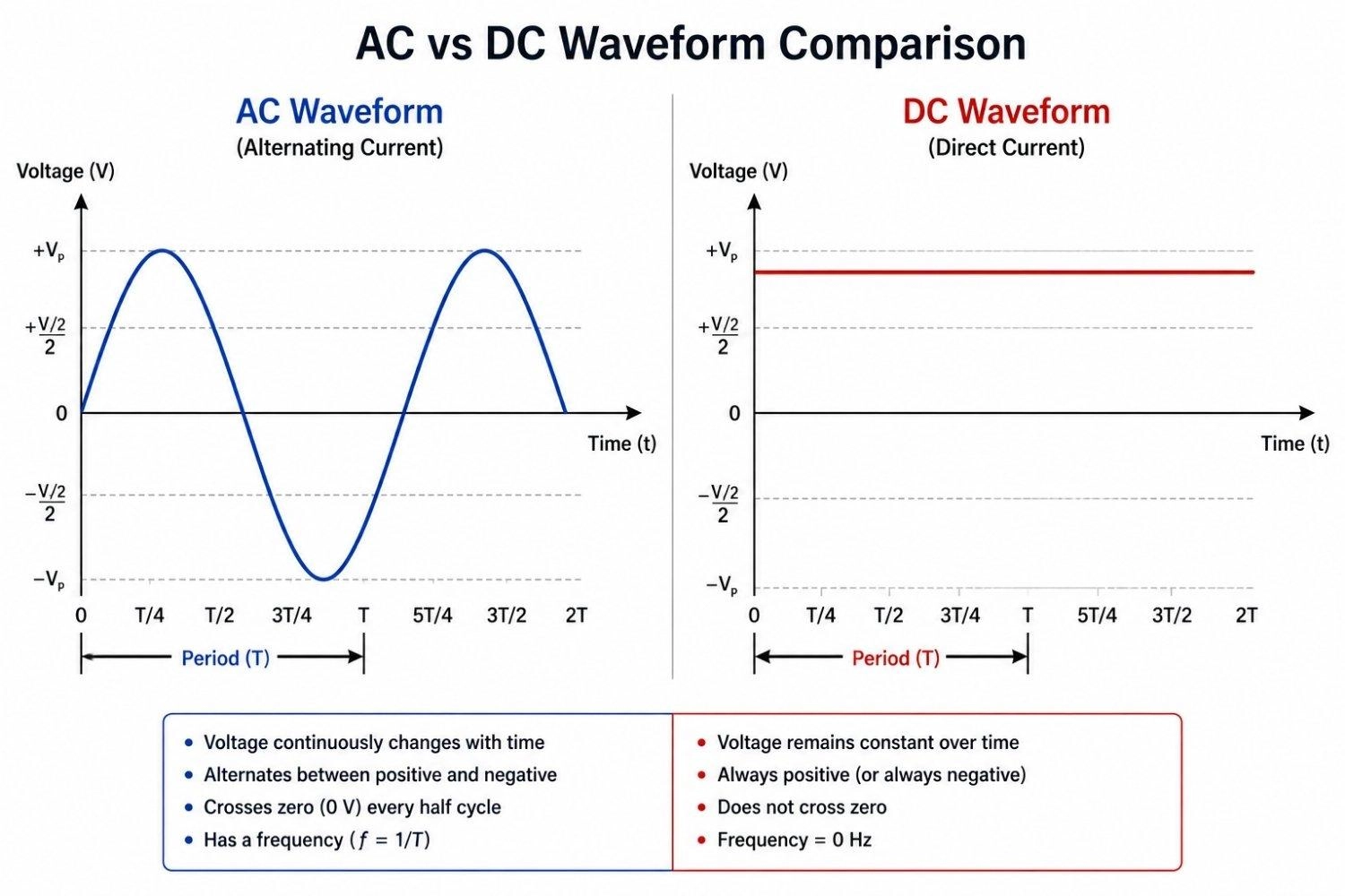
Figure: Comparison of alternating current (AC) and direct current (DC) waveforms.
What Is Electric Current?
Electric current is the net movement of electric charge (primarily electrons) through a conductor like a copper wire. A fully functional circuit requires:
- A voltage source (battery, generator, or power supply)
- A closed loop
- A conductive path
- A load (resistor, motor, or LED) to do useful work
Engineers analyze circuits using conventional current, defined as flowing from the positive terminal to the negative terminal. Although electrons move in the opposite direction, conventional current remains the standard convention used in schematics and circuit analysis.
AC and DC describe how electric current behaves over time.
Key Takeaway
Current is charge in motion. AC reverses its direction of flow periodically, while DC maintains a single, unidirectional path.
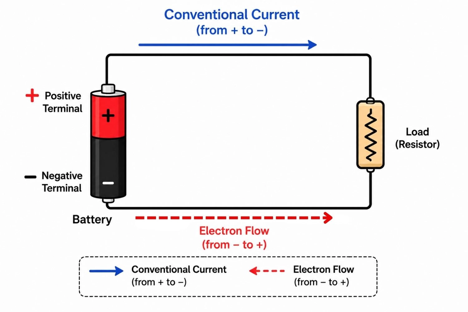
Figure: Circuit diagram showing conventional current direction versus electron flow.
What Is Alternating Current (AC)?
Alternating current (AC) is an electric current that periodically reverses its flow. Its magnitude and direction change continuously over time, cycling between positive and negative limits. The most common AC waveform is the sine wave, representing smooth, harmonic oscillation.
The key parameters defining an AC signal are:
- Frequency: Measured in Hertz (Hz), this represents the number of full cycles completed per second. Most global power grids run at either 50 Hz or 60 Hz.
- Period: The time required to complete one full cycle (1 divided by frequency).
- RMS Voltage (Root Mean Square): Because AC voltage is constantly moving, peak voltage is not a practical value for power calculations. RMS represents the equivalent DC voltage that would produce the equivalent heating effect in a resistive load. When you read "230V" on a home outlet, this is the RMS value, whereas the actual peak voltage is closer to 325V.
Engineering Note
Although utility power is sinusoidal, alternating current can also have square, triangular, or other periodic waveforms in electronic systems.
Grid power is globally distributed as AC because its voltage can be easily stepped up or down with transformers, making it highly efficient for long-distance transmission.
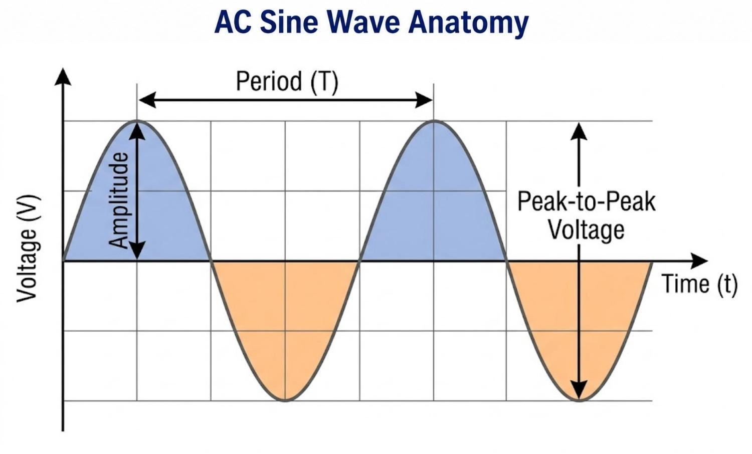
Figure: AC sine wave anatomy diagram showing positive/negative half-cycles, amplitude, and period.
Common AC Grid Standards Around the World
| Region | Frequency (Hz) | Standard RMS Voltage (V) |
|---|---|---|
| North America | 60 Hz | 120 V |
| Europe | 50 Hz | 230 V |
| Australia | 50 Hz | 230 V |
| Bangladesh | 50 Hz | 220 V to 230 V |
What Is Direct Current (DC)?
Direct current (DC) flows strictly in one direction. Since it does not repeat periodically, an ideal DC signal has a frequency of 0 Hz. DC voltage can either be completely flat and constant (as provided by a lithium-ion cell or battery) or pulsating (as seen after passing an AC waveform through a rectifier without fully smoothing it).
Despite potential fluctuations in voltage, the current never crosses the zero-voltage line to reverse direction.
DC acts as the native operating standard for energy storage and low-voltage electronics:
- Batteries and lithium cells (smartphones, laptops, power tools)
- Power banks
- USB ports and chargers
- Solar panels, before any inversion to AC
DC vs AC is therefore not just a theoretical distinction. It directly determines which devices can connect to which power source without conversion hardware.
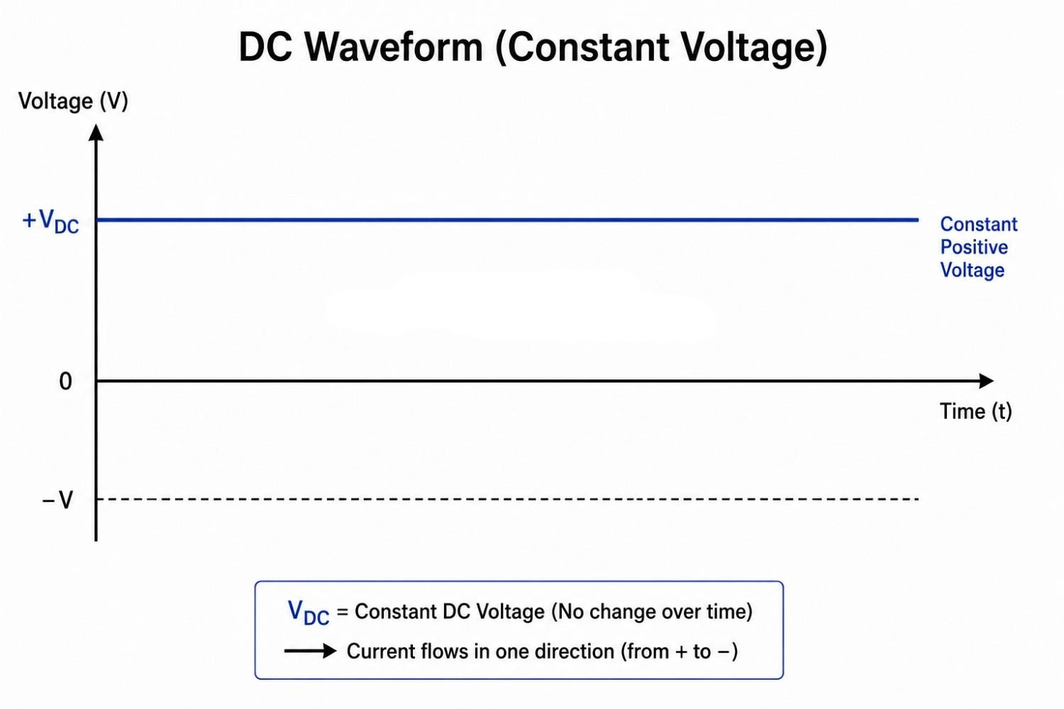
Figure: DC waveform graph showing constant voltage over time.
Why Is AC Used for Power Transmission?
AC is preferred for transmission because:
- Voltage is easily changed using transformers.
- Higher voltage lowers current.
- Lower current reduces I^2R losses.
- Transmission becomes more efficient.
Power transmission efficiency is governed by Joule's Law:
P_loss = I^2 * R
Where P_loss is power lost as heat, I is the current, and R is the resistance of the line. By stepping up the AC voltage to ultra-high levels (such as 400,000V) before transmission, the current (I) drops proportionally for the same total power output. Lowering the current reduces the heat losses dramatically, saving enormous amounts of energy.
AC dominates long-distance power transmission because step-up and step-down transformers work using magnetic induction, requiring an alternating magnetic field. Since DC is static, it cannot operate with simple passive transformers.
While AC distribution is standard, High-Voltage Direct Current (HVDC) transmission is used for specific long-distance underwater lines or when linking non-synchronized regional power grids. HVDC experiences lower capacitive losses over long paths but requires expensive, complex terminal converter stations at each end.
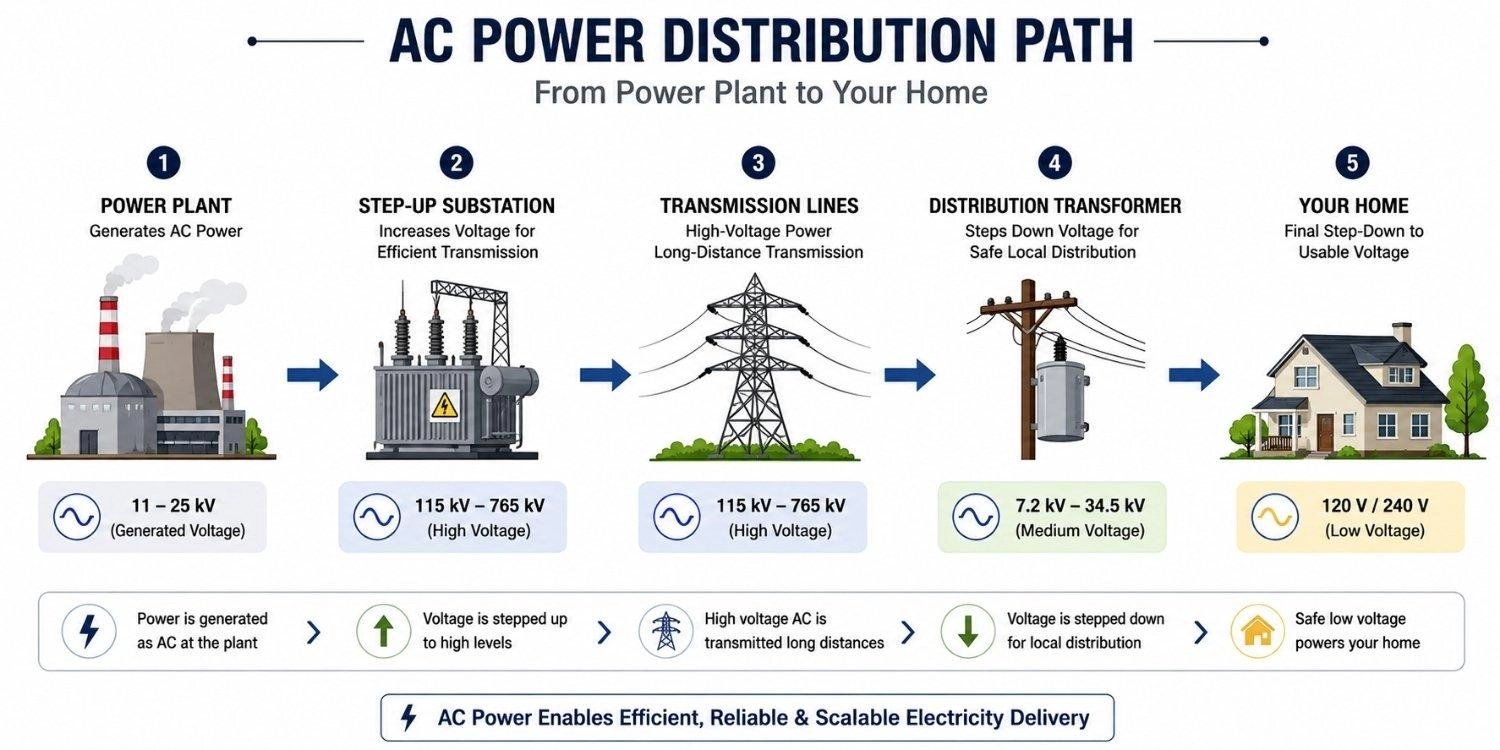
Figure: Showing step-up and step-down AC power distribution from the generator to the household.
Why Do Electronics Use DC?
Digital microcontrollers like the STM32 or ESP32, together with active sensors, processors, and flash memory, require stable DC voltages (often 5V, 3.3V, or even lower).
Examples include smartphones, laptops, Wi-Fi routers, IoT devices, and embedded systems. Microscopic transistors inside integrated circuits function as high-speed switches. To reliably distinguish between logic low (0V) and logic high (e.g., 3.3V), the voltage rails must remain flat and predictable.
If AC were applied directly to an integrated circuit, the voltage would swing continuously, preventing logic gates from functioning and potentially damaging sensitive semiconductor devices.
Because modern devices require both robust structures and compact assembly, designers must weigh their mounting configurations. Our article on surface mount vs through-hole technologies explains how these components are placed on a board to manage DC power distribution efficiently.
When designing high-speed digital boards, incorporating a decoupling strategy is critical to filter out noise on the DC power rail. You can read more about this in our comprehensive guide on bypass capacitors.
- Whether you're designing an AC power supply, a DC-powered device, or a mixed-signal system, the next step is turning your schematic into reliable hardware.
- JLCPCB provides high-quality PCB fabrication, component sourcing, and professional PCB assembly services to help you move efficiently from prototype to production.
How Is AC Converted to DC (and Vice Versa)?
AC to DC Conversion
AC-to-DC conversion typically involves four stages:
- Step-Down Transformer: Lowers high wall outlet voltage (e.g., 230V RMS) to a safe, low level (e.g., 9V RMS).
- Bridge Rectifier: Uses four diodes arranged in a loop to redirect the negative half-cycles of the AC wave, turning them into a pulsating positive waveform.
- Smoothing Filter: A large polarized filter capacitor absorbs charge during voltage peaks and discharges when the voltage drops, flattening the output. Be sure to reference our capacitor polarity guide to ensure correct orientation during assembly.
- Voltage Regulator: An IC that maintains a flat, locked output voltage (like a clean 5V DC) despite any remaining ripple or input line variations.
This rectifier and regulator chain is the same basic topology found inside USB chargers, laptop power bricks, and onboard power supplies on most PCB designs.
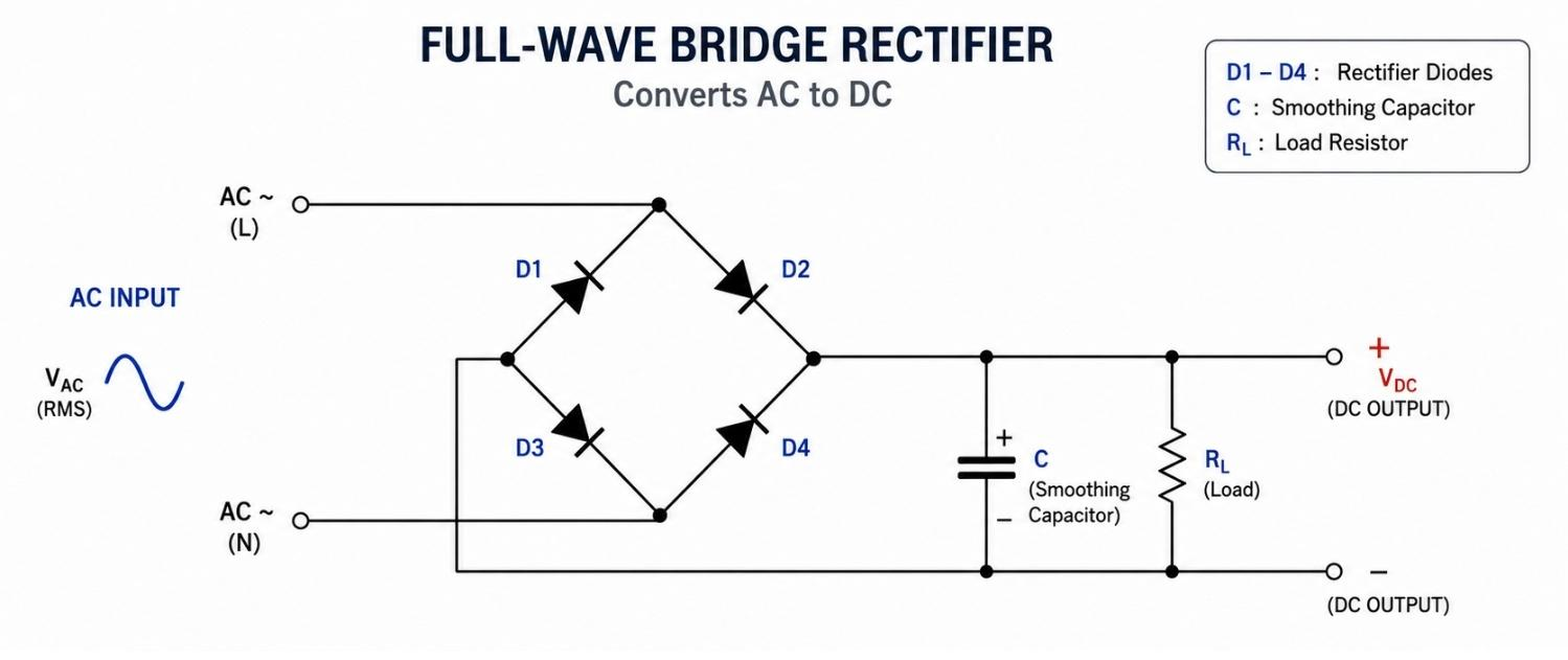
Figure: Circuit diagram of a full-bridge rectifier showing AC input conversion to a smoothed DC output.
DC to AC Conversion
A typical inverter converts DC into AC through three stages:
- High-Speed Switching: Power switches alternate the direction of DC current flowing through a load. For a deeper look at the semiconductors that perform this switching, see our technical differences between BJTs and MOSFETs.
- Pulse-Width Modulation (PWM): Microcontrollers adjust the width of switching pulses to approximate the area under a sine wave curve.
- Filtering: Inductors and capacitors smooth the pulsed high-frequency output into a clean, low-distortion sine wave.
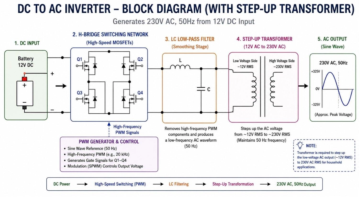
Figure: A DC-to-AC power inverter showcasing H-bridge switching, PWM modulation, and LC filter stage.
Inverters are essential for backup UPS systems, solar arrays feeding power back into the grid, and electric vehicles where battery DC must run high-power AC traction motors.
Key Takeaway
Rectifiers convert AC to DC for electronics; inverters convert DC to AC for grid-tied or AC-only loads.
AC and DC in Everyday Devices: Real-World Examples
| Device | AC or DC | Why |
|---|---|---|
| Smartphone | DC | Battery and internal circuits run on DC; the wall charger converts AC to DC |
| Washing machine | AC* | Traditional motors run directly on AC; *modern inverter/BLDC models convert to DC internally |
| Solar panel | DC | Photovoltaic cells generate DC directly from sunlight |
| Electric oven | AC | Resistive heating elements work off AC directly, no conversion needed |
| Laptop motherboard | DC | All internal chips run on low-voltage DC; the power adapter handles AC-to-DC conversion |
| Wind turbine | AC | The generator's rotating magnetic field naturally induces AC |
| EV battery | DC | Battery cells store and release DC, regardless of the charging station's input type |
Advantages and Disadvantages of AC and DC
Alternating Current (AC)
- Pros: Highly efficient over long grid lines; simple voltage changes using passive transformers; AC alternators are structurally robust.
- Cons: Cannot be stored directly in batteries; reactive impedance causes losses in transmission lines; requires conversion overhead for digital devices.
Direct Current (DC)
- Pros: Native compatibility with all microprocessors and digital electronics; quiet, constant power rails; highly efficient storage in chemical batteries.
- Cons: Harder to step up or down in voltage without switching regulators; high-voltage DC is challenging to interrupt due to persistent arcing.
FAQs about Alternating Current and Direct Current
Q: What is the difference between AC and DC?
The primary difference lies in the direction of the electric charge. Alternating current (AC) periodically reverses its direction in a repeating cycle, whereas direct current (DC) flows continuously in one constant direction. AC is ideal for utility power grids, while DC natively powers electronics and batteries.
Q: Is a battery AC or DC?
A battery is a DC source. Its internal chemical reactions drive electrons in one consistent direction through the external circuit.
Q: Is USB AC or DC?
USB always delivers DC. Standard USB ports output 5V DC, whereas advanced USB Power Delivery (USB-PD) standards dynamically negotiate voltages up to 20V or 48V DC over Type-C connections.
Q: Are solar panels AC or DC?
Solar photovoltaic cells generate DC directly via the photoelectric effect. This DC power must pass through a grid-tie or off-grid inverter to run standard AC household appliances.
Q: Why does the power grid use AC?
The main advantage of AC for power grids is that voltage can be converted up and down efficiently using transformers, which minimizes line losses over hundreds of miles.
Q: Can AC charge a DC battery?
AC must first be rectified and regulated into DC before charging a battery.
Q: Which is safer, AC or DC?
Both are hazardous at high voltages. However, AC is generally more likely to cause dangerous heart fibrillation at lower thresholds (50 Hz to 60 Hz matches the frequency range of human neuromuscular response closely), whereas DC shocks often cause a single muscular contraction that can forcibly throw a person away from the contact source.
Q: Can AC and DC work together?
Yes, this is common practice. Modern electronics rely on hybrid power structures. For instance, a smart home hub plugs into an AC wall outlet but immediately rectifies that power to run its internal DC microcontroller.
Conclusion
AC and DC are complementary systems. AC remains the premier standard for long-range power distribution, while DC is the undisputed standard for digital processing, batteries, and portable consumer electronics. Modern systems smoothly transition between both formats using efficient switching converters and rectifiers.
Popular Articles
• How to Create a Bluetooth-Controlled Car With Arduino: A Step-by-Step Guide
• How to Design and Assemble a Reliable ESP32 Module PCB on a 2-Layer Board
• The Ultimate Guide to Relay Symbol: Coil, Contacts, Diagrams, and Circuit Applications
• How to Identify SMD LED Polarity: Markings, Testing, and PCB Tips
• The Ultimate Guide to PCBA: Process,Types and Techniques for the Electronics Enthusiast
Keep Learning
How to Design an ESP32-S3 Development Board from Scratch: A 4-Layer PCB Design Tutorial
Designing your own ESP32-S3 development board gives you complete control over your hardware architecture while preparing your IoT projects for commercial production. Instead of relying on bulkier, off-the-shelf boards, building a custom design allows you to optimize the board space, expose only the required GPIO pins, and integrate peripherals directly onto a single substrate. In this tutorial, we will design a 4-layer ESP32-S3 development board from scratch. We will walk through the entire hardware d......
Arduino LED Driver Tutorial: Control More LEDs with 74HC595 and MAX7219
Arduino GPIO pins run out quickly in larger LED projects. By utilizing dedicated LED drivers and expansion ICs, you can drastically reduce pin usage, eliminate processor-heavy multiplexing loops, and simplify display wiring. In this guide, you will learn the operational architecture, wiring configurations, cascading techniques, and optimization strategies for the 74HC595 shift register and the MAX7219 LED driver. Why Arduino Projects Need LED Driver ICs Arduino GPIO and Current Limitations An ATmega32......
How to Create a Bluetooth-Controlled Car With Arduino: A Step-by-Step Guide
This tutorial walks through the complete engineering and implementation of a two-wheel Bluetooth RC car with an Arduino Nano module on a specially designed PCBA (Printed Circuit Board Assembly). While many hobbyists start by wiring motors and Bluetooth modules with jumper cables on a breadboard, this approach is prone to disconnection and signal noise. This guide upgrades that process by teaching you how to design a professional mainboard. Key Design Features Controller: Arduino Nano used as a plug-in......
Fiducial Marks in PCB and SMT Assembly: A Complete Guide to Accuracy and Design Rules
Modern Printed Circuit Boards (PCBs) are complex, integrating high-density components like 0.4mm pitch Ball Grid Arrays (BGAs), 0201 passives, and fine-pitch Quad Flat No-Lead (QFN) packages. In this advanced manufacturing environment, achieving placement accuracy measured in micrometers is crucial. A significant challenge in automated manufacturing is how pick-and-place machines, which handle thousands of components per hour, precisely locate the PCB. A board on a conveyor system is never in the perf......
Alternating Current vs Direct Current (AC vs DC): What's the Difference?
Electric current flows in two primary forms: alternating current (AC) and direct current (DC). AC periodically reverses direction, while DC flows steadily in one direction. AC powers the industrial and residential electrical grids, while DC powers batteries, electric vehicles, and nearly all modern consumer electronics. Understanding the core differences between AC and DC matters when designing power supplies, selecting electronic components, or laying out printed circuit boards (PCBs). This guide com......
Arduino LED Multiplexing Tutorial: Control More LEDs with Fewer Pins
The Arduino Uno is a powerful tool for prototyping, but driving multiple LEDs directly quickly exhausts its 20 GPIO pins and its 200 mA absolute maximum package current limit. To bypass these hardware bottlenecks, engineers and hobbyists use LED multiplexing to scale display outputs efficiently without upgrading the microcontroller. In this guide, you will learn the core principles of LED matrix scanning, Charlieplexing, refresh timing, ghosting fixes, and practical Arduino code without relying on any......