
Flex PCB Assembly Guide: Process, Challenges, and Solutions
12 min
- What is Flex PCB Assembly?
- Why Flex PCB Assembly Isn't Like Rigid-Flex PCB Assembly?
- The Full Process of Flex PCB Assembly (FPCA)
- Flex PCB Assembly Challenges: Technical Complexity and Cost Drivers
- From PCB Design to Dependability: Why JLCPCB is a Reliable Manufacturer for Flex PCB Assembly
- FAQ about Flex PCB Assembly
- Conclusion: Flex PCB Assembly
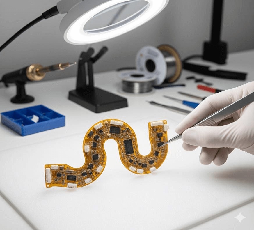
Flexible Printed Circuit Boards (Flex PCBs) are the foundational technology enabling the compact, innovative design of modern electronics. Because of their ability to bend and fold, they power devices from smart wearables to compact medical instruments where traditional rigid printed circuit boards (Rigid PCBs) can't be used.
Achieving a functional electronic circuit from the raw plastic film demands special expertise, with flexible PCB assembly (FPCA) representing the crucial final step in this transformation.
What is Flex PCB Assembly?
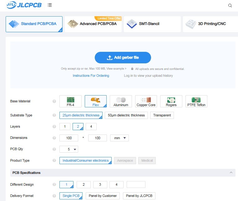
Flex PCB assembly (FPCA) is the process where electronic components are mounted, soldered, and assembled directly onto a flexible circuit substrate, which is typically a thin-film Polyimide (PI). At this stage, an incomplete circuit board becomes a fully working electronic assembly. Although the core objective is to make a reliable connection, the non-rigid nature demands significant modifications to the traditional assembly techniques.
Why Flex PCB Assembly Isn't Like Rigid-Flex PCB Assembly?
It is important to know which components we are attaching to the rigid-flex or pure flexible circuit when organizing the assembly. Stability and thermal stress control are the main differences in the assembly.
Continuous external stabilization is needed for the pure flex circuit board assembly. The circuit must be fixed to a rigid carrier pallet (jig) at every stage, from solder paste printing to component placement, because the entire circuit is floppy and composed solely of the bendy Polyimide (PI) film. This stabilization is necessary to maintain the dimensional accuracy, since it ensures the precise alignment of components on the flexible substrate.
Conversely, the rigid-flex PCB assembly has the advantage of permanent FR4 sections, which offer stability. As most assembly takes place in these rigid zones, full-board external carriers are not required for stability. But controlling the inherent thermal mismatch becomes difficult during the reflow soldering. Because the stiff and flexible sections grow unevenly when heated, the PCB manufacturer has to use an extremely careful, slow heat process. This helps reduce the chance of bubbling, layer separation, and stress fractures in the transition areas.
-
Core difficulty
Maintaining the dimensional flatness of the thin, floppy board throughout assembly.
-
Stabilization
Requires continuous external support — a rigid carrier jig at every stage.
-
Core difficulty
Precise control of stress and heat across stiff and bendy materials.
-
Stabilization
Permanent FR4 zones provide stability, but thermal mismatch risks bubbling and delamination.
The Full Process of Flex PCB Assembly (FPCA)
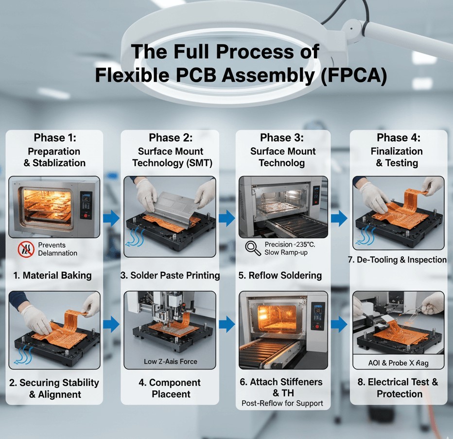
Although it includes some crucial and specialized steps, the flexible PCB assembly process largely follows the standard Surface Mount Technology (SMT) flow.
Phase 1: Preparation and Stabilization
-
Incoming Quality Control (IQC) and Material Baking
Since flexible materials are hygroscopic, they absorb moisture. For this reason, all bare flex boards must be routinely pre-baked in a controlled oven before assembly. This prevents the moisture from turning into steam and causing delamination during soldering.
-
Securing the Flexible Circuit (Tooling)
This is a fundamental step. The flexible circuits must be mounted onto a rigid carrier pallet or jig — often high-temperature aluminum or composite — which provides the necessary flatness and mechanical stability for automated processing via pin alignment or vacuum suction.
Phase 2: Surface Mount Technology (SMT)
-
Solder Paste Printing
Solder paste is applied through a laser-cut stainless steel stencil. The PCB is securely fixed to a jig to maintain flatness and precise alignment during printing. Accurate vision alignment is crucial, as even a slight misalignment can cause solder bridging or open circuits, especially for fine-pitch components. To ensure consistent deposition, a metal squeegee is typically used, while polyurethane blades may be used for flexible or sensitive substrates.
-
Component Placement (Pick-and-Place)
Surface Mount Devices (SMDs) are placed accurately onto the paste by high-speed SMT machines. The downward Z-axis force of the machine is carefully calibrated to seat the component correctly, avoiding deformation of the material.
-
Reflow Soldering (Tight Thermal Control)
The assembly passes through a forced hot air convection oven while remaining mounted on the carrier jig. The reflow profile is tightly controlled and set at the lower end of the solder paste manufacturer's recommended temperature range to minimize thermal stress on thin substrates.
-
Lower Peak Temperature: typically maintained below 235 °C to protect temperature-sensitive materials such as polyimide substrates.
Slower Ramp-up Rate: a controlled ramp-up rate helps prevent thermal shock and substrate warping in thin or flexible boards.The carrier jig is crucial during this process, as it ensures uniform heat distribution and mechanical stability across the assembly.
Phase 3: Finishing and Finalization
-
Post-Reflow Attachment of Stiffeners and Through-Hole Components
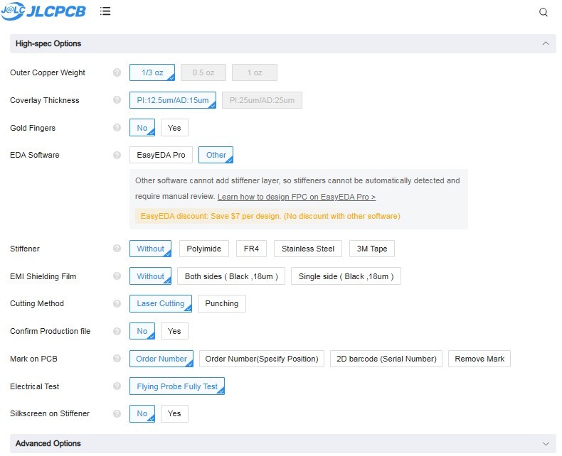
If the design specifies rigid areas for connectors or heavy components, stiffeners (made of FR4 or a thicker PI film) are usually thermally bonded to the flex circuit after reflow to give structural support to the solder joints. To prevent the entire body from being exposed to high heat again, any through-hole components are added via specialized selective soldering or manual processes.
-
De-Tooling and Inspection
The assembled flex circuit is then carefully removed from the carrier pallet, a step called de-tooling. The placements and other defects (shorts or voids) are inspected by Automated Optical Inspection (AOI).
-
Electrical Testing and Final Processing
Electrical functionalities are verified by Flying Probe Testing or In-Circuit Testing (ICT). For protection against abrasion, moisture, and chemicals, a conformal coating is often applied to the flexible sections. Then the final product is cut to its required shape and packaged carefully to prevent damage during shipment.
Flex PCB Assembly Challenges: Technical Complexity and Cost Drivers
Just performing the steps isn't the only difficulty in flex PCB assembly; reducing the risks of working with soft material is also crucial. So, when compared to rigid PCB assembly, these technical issues inevitably result in higher costs and greater complexity.
Technical Challenges in Flex PCB Assembly
-
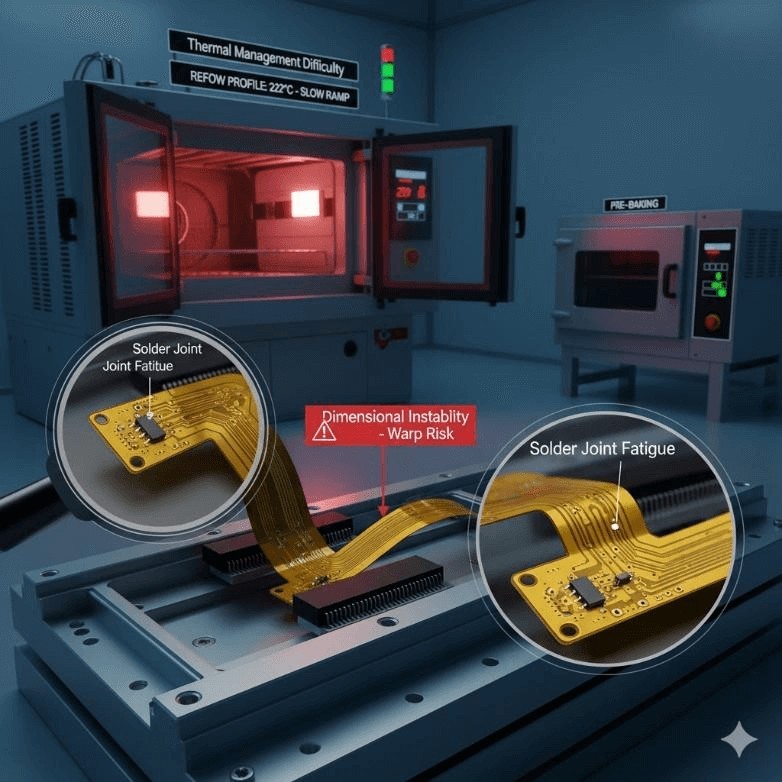
Solder Joint Fatigue and Fracture: This is the main issue with long-term dependability. Components often fail near bending regions. As a thin PI substrate is not a good stress absorber, any movement can cause a fracture in the fragile solder joints. The solution involves additional fabrication and assembly steps and necessitates the inclusion of additional stiffeners and precise teardrop shapes in the design.
-
Dimensional Instability: Since Polyimide (PI) is highly sensitive to heat and moisture, it can shrink, stretch, and warp. This makes it difficult to achieve precise component alignment and layer-to-layer registration. Hence, pre-baking and advanced machine vision systems with constant re-registration checks are unavoidable, which slows down the process.
-
Thermal Management Difficulty: Compared to FR4, the PI film has a significantly lower glass transition temperature (Tg). Because of this, the assembly house needs to maintain specialized, slower low-temperature reflow profiles, which increase cycle times and require dedicated ovens.
Key Factors Driving Flex PCBA Cost
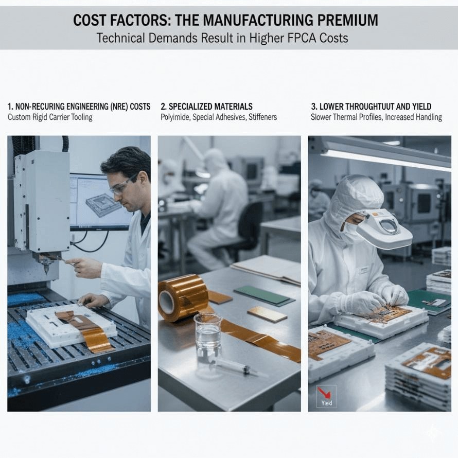
These technical demands directly result in a higher cost structure for flex PCB assembly (FPCA):
-
Non-Recurring Engineering (NRE) Costs: A big upfront cost is paying for the rigid carrier tooling (jigs) required for each different flexible circuit. These tools are needed to keep the floppy circuits flat, but they must be precisely machined, which adds significant upfront cost (especially for small volumes).
-
Specialized Materials: Compared to standard FR4 and rigid materials, the addition of special flexible substrate (Polyimide), adhesives, and stiffeners increases the cost.
-
Lower Throughput and Yield: Due to the requirement of slower, softer thermal profiles and the longer handling time, the cost per unit increases and the manufacturing speed is reduced.
Specialized equipment, strict process control, and knowledge that costs more than standard rigid SMT services are all necessary for the successful assembly of a flexible PCB.
From PCB Design to Dependability: Why JLCPCB is a Reliable Manufacturer for Flex PCB Assembly
One of the most critical stages in a flex PCBA project is selecting a reliable manufacturing partner — one capable of addressing the mechanical stresses, thermal management challenges, and assembly process precision required by flexible substrates.
JLCPCB provides a highly automated and precisely controlled manufacturing framework specifically optimized for flex circuit board assembly, enabling complex flex PCB designs to be manufactured and assembled with consistency and reliability.
The overall reliability of a flexible circuit depends heavily on the manufacturer's control of every fabrication and assembly stage. JLCPCB's proven dependability comes from integrated, specialized capabilities that directly address key Flex PCB Assembly challenges:
Why JLCPCB for Flex PCB Assembly
- Guaranteed stability through specialized handling: dedicated high-precision SMT lines with sophisticated vision systems and customized carrier tools remove the flexible material's dimensional instability, ensuring accurate component placement and high yield.
- Mitigation of thermal risk: specialized, verified low-temperature thermal profiles maintain strict process control, protecting delicate solder joints for long-term dependability.
- Seamless vertical integration: handling both flex PCB fabrication and assembly under one roof eliminates hand-off delays, shipping issues, and communication gaps, and allows early optimization of panel layout and stiffener placement.
Ultimately, JLCPCB provides the necessary ecosystem of extreme flex circuit board assembly process control, integrated support, and demonstrated expertise. JLCPCB does more than just assemble — we confidently offer the flex PCB manufacturing solutions required to convert intricate, flexible designs into dependable, practical flexible PCB assemblies that turn your project into reality.
Check more details: PCB Manufacturing & Assembly Capabilities - JLCPCB
FAQ about Flex PCB Assembly
Q1: What are the most common assembly defects seen in Flexible PCBs, and how can they be prevented?
Material movement and inadequate temperature control are the primary causes of common flex PCB assembly defects, such as solder bridges, lifted pads, and cracked joints. These issues often occur because the flexible substrate lacks mechanical rigidity during assembly.
Prevention begins with accurate component placement, tight thermal process control, and proper jig or carrier setup to maintain flatness. Pad lifting can be reduced by using stiffeners or adhesion promoters that reinforce dense circuit areas. Regular Automated Optical Inspection (AOI) and X-ray inspection after soldering help identify hidden defects early, improving yield and reducing costly rework.
Q2: Why is continuous external stabilization (tooling) a fundamental step in flex PCB assembly?
Continuous external stabilization is necessary because the pure flexible circuit is floppy and lacks inherent mechanical stability. The circuit must be mounted onto a rigid carrier pallet (jig) at every stage to provide the necessary flatness. This is a fundamental step that ensures dimensional accuracy and allows for the precise alignment of fine-pitch components during automated processes like solder paste printing and component placement.
Q3: How do environmental conditions affect the long-term reliability of flexible PCBs?
Flexible PCBs are susceptible to corrosion, delamination, and electrical parameter drift due to exposure to moisture, dust, and temperature fluctuations.
To enhance reliability in harsh environments — such as automotive or medical systems — manufacturers employ humidity-controlled storage, conformal coating, and high-Tg polyimide materials with encapsulation layers for added protection. Maintaining cleanroom conditions throughout production further minimizes contamination and ensures long-term reliability and performance stability.
Q4: What factors should be considered when selecting materials for a Flexible PCB Assembly project?
Selecting the right materials is crucial to achieving an equilibrium among cost, flexibility, and thermal insulation. In real-world flexible PCB assembly projects:
- Base Film: Polyimide (PI) is preferred for flexible circuits due to its outstanding heat resistance and shape stability. PET is less costly but performs best in less demanding or low-temperature applications.
- Copper Foil Type: Compared with Electro-Deposited (ED) copper, Rolled Annealed (RA) copper provides higher ductility and fatigue resistance, making it more suitable for repeated flexing applications.
- Adhesive System: Although acrylic adhesives tend to be mechanically flexible, their tendency to absorb moisture can undermine longevity. Highly precise circuit applications benefit significantly from adhesive-free laminates' outstanding dimensional stability.
- Surface Finish: Greater longevity and performance can be guaranteed through ENIG and Immersion Silver finishes that improve soldering efficiency while protecting the board from corrosion.
Achieving the highest durability and manufacturing flexibility depends on choosing a material aligned with the device's bending cycles, thermal environment, and mechanical stress conditions.
Q5: What is the main difference in assembly difficulty between a Flex PCB and a Rigid-Flex PCB?
- Flex PCB Assembly: Maintaining the flatness of the flexible substrate throughout the entire assembly process is a major challenge. Dedicated carrier jigs must be used during printing, component placement, and reflow to ensure process stability and dimensional consistency.
- Rigid-Flex PCB Assembly: Support fixtures are sometimes required because the board includes rigid FR4 regions that provide mechanical stability. During reflow, the flexible and rigid layers expand at different rates, introducing thermal and mechanical stress at the junctions. The key challenge lies in precisely controlling the thermal profile and mechanical pressure to avoid delamination and warping.
Conclusion: Flex PCB Assembly
Unlike rigid PCB, flexible PCB assembly is a unique manufacturing challenge. Three key areas must be mastered for success: thermal control (using slow, low-temperature reflow profiles), dimensional accuracy (through pre-baking and advanced vision systems), and mechanical stability (use of carrier tooling and stiffeners).
The increase in cost and complexity is directly caused by technical difficulties such as solder joint fatigue and material heat sensitivity. In the end, choosing the right and trustworthy partner with specialized equipment and integrated process expertise is necessary to achieve dependable FPCA.
Popular Articles
• Common PCB Assembly Methods and Soldering Techniques Explained
• What Is BGA Void? Causes, IPC Limits, and Solutions
• SMD Soldering Tools You Need: Complete Guide from Beginner to Pro
• Reflow Soldering: Everything You Need to Know
• SMT Assembly Process Explained and Equipment Used: A Step-by-Step Guide to PCBA Manufacturing
Keep Learning
Common PCB Assembly Methods and Soldering Techniques Explained
Whether you're designing your first prototype or scaling up to production, understanding PCB assembly methods and soldering techniques is crucial to achieving reliable, high-performance circuit boards. Modern PCBA primarily relies on Surface Mount Technology (SMT) and Through-Hole Technology (THT)—each offering unique advantages for component density, durability, and manufacturability. In this guide, we'll break down the major PCB assembly methods, key soldering techniques such as reflow and wave sold......
12 Professional Soldering Tips and Tricks Every Beginner Should Know
Soldering is not merely "gluing" metal; it is a metallurgical process that creates an intermetallic compound (IMC). This molecular bond ensures the electrical and mechanical integrity of your device. A poor joint might pass a quick visual check but will inevitably fail under vibration or thermal stress, leading to "ghost" bugs and hardware failures. These soldering tips and tricks focus on practical, repeatable techniques used in professional electronics soldering—from correct heat transfer and flux u......
Solder Melting Point Guide: Chart, Alloy Types, and Reflow Considerations
In the precise world of electronics manufacturing, a difference of just a few degrees can mean the distinction between a perfect, reliable solder joint and a catastrophic "cold" joint failure. While many hobbyists view soldering simply as "melting metal to stick things together," professional PCB assembly requires a nuanced understanding of thermodynamics. The solder melting point is not simply a single value listed in a datasheet; it is a decisive limit that determines the choice of components, the s......
The Ultimate Guide to Solder Flux: Everything You Should Know Before Soldering PCB
Soldering is needed to make almost all electronic devices. Adding solder alone won't make a joint that is strong, clean, and sound from a metallurgical point of view. Solder flux is a very important part of the process that comes in here. If you want to do your job better and make it more reliable, you need to know a lot about soldering flux, whether you're an engineer, a professional technician, or just a hobbyist. This article goes into a lot of detail about solder flux, including what it is, how it......
Flex PCB Assembly Guide: Process, Challenges, and Solutions
Flexible Printed Circuit Boards (Flex PCBs) are the foundational technology enabling the compact, innovative design of modern electronics. Because of their ability to bend and fold, they power devices from smart wearables to compact medical instruments where traditional rigid printed circuit boards (Rigid PCBs) can't be used. Achieving a functional electronic circuit from the raw plastic film demands special expertise, with flexible PCB assembly (FPCA) representing the crucial final step in this trans......
SMD Rework Guide: Tools, Temperatures, and Techniques That Prevent PCB Damage
From replacing a burned regulator to correcting wrong component values or removing solder bridges on fine-pitch ICs, SMD rework is an essential skill in electronics manufacturing and prototyping. It allows engineers to repair assembly defects, implement design changes, and recover valuable PCBs without the cost and delay of building new boards. In this guide, you will learn: What SMD rework is Common rework scenarios Tools and temperatures Safe removal and installation Package-specific techniques Real......