
BGA Rework: Complete Guide to Process, Tools, and Repair Techniques
14 min
- BGA Rework at a Glance
- What Is BGA Rework?
- BGA Rework Process [Step-by-Step]
- BGA Rework Tools and Equipment
- BGA Rework vs BGA Reballing
- Common Challenges in BGA Rework
- Common Mistakes to Avoid During BGA Rework
- Best Practices for Successful BGA Rework
- Mitigating BGA Rework with Reliable PCB Assembly
- When to Choose Professional BGA Rework Services
- FAQs
- Conclusion
As modern PCB designs continue to shrink in size while increasing in complexity, Ball Grid Array (BGA) packages have become essential for high-performance electronics such as processors, FPGAs, and memory devices. However, because BGA solder joints are located beneath the component body, repairing or replacing these devices is far more challenging than traditional surface-mount components.
BGA rework is a specialized process used to safely remove, repair, or replace defective BGA components without damaging the PCB. It requires precise thermal control, proper alignment, and advanced inspection techniques to ensure reliable solder joint formation.
This guide explains the complete BGA rework process, the tools required, common challenges, and best practices for achieving successful PCB repairs.
BGA Rework at a Glance
Aspect | Description |
|---|---|
Process | Removing, cleaning, and replacing defective or misaligned BGA components. |
Common Method | Removal → Pad cleaning → Reballing → Alignment → Reflow |
Tools Needed | BGA rework station, tacky flux, desoldering braid, reballing stencils. |
Inspection | X-ray inspection or Automated Optical Inspection (AOI) to verify hidden joints. |
What Is BGA Rework?
BGA rework is the process of safely heating a Ball Grid Array component to its solder liquidus temperature, removing the chip, cleaning the residual solder from the PCB, and then installing a new or reballed component using a strictly controlled thermal profile.
Why BGA Components Require Rework
Despite advances in automated PCBA manufacturing, defects still occur. BGAs require rework primarily because their hidden joints are susceptible to hidden failures.
If the initial reflow profile in the factory was slightly off, it could result in cold solder joints, voiding (trapped gas bubbles inside the solder), or bridging (two solder balls melting together to cause a short circuit).
Furthermore, because BGAs are rigidly soldered to the fiberglass (FR4) substrate, physical drops or extreme thermal cycling during the device's lifespan can cause the microscopic solder spheres to fracture.
Typical Scenarios Where Rework Is Needed
- Prototyping Errors: An engineer discovers a design flaw in a prototype run and needs to swap a processor for a different model.
- Component Failure: A costly motherboard or server board has a single dead GPU or memory chip that must be replaced to save the entire assembly.
- Manufacturing Defects: Post-assembly X-ray inspection reveals internal bridging or voiding that must be corrected before the board ships.
- Upgrades: Swapping a lower-capacity flash memory chip for a higher-capacity one on an existing PCB.
BGA Rework Process [Step-by-Step]
A successful repair relies on a repeatable, tightly controlled BGA rework procedure. Skipping or rushing any of these steps dramatically increases the risk of destroying the board.
Step 1: Removing the Defective BGA Chip
The board is first secured in a rework station and globally preheated from the bottom to prevent warping. A top heater then applies a specific thermal profile to the defective chip. Once the solder spheres reach their melting point, a vacuum pickup tube automatically lifts the component off the board. It is crucial never to pry or force the chip, as this will tear the fragile copper pads off the PCB.
Step 2: Cleaning the PCB Pads (Site Redressing)
Once the chip is removed, the PCB pads will be covered in uneven, oxidized residual solder. The technician applies generous amounts of tacky flux and uses a wide-chisel soldering iron paired with conductive desoldering braid (wick) to gently wipe the pads flat.
The goal is to leave a perfectly smooth, uniform surface without scratching the solder mask or ruining the original solder pad design.
Step 3: Reballing the BGA Component
If the removed chip is expensive and still functional, it can be saved. However, it needs new solder spheres. The technician cleans the bottom of the chip, clamps a precision-machined metal stencil over it, and applies new solder paste or solid solder spheres. The chip is then reflowed to attach the new balls.
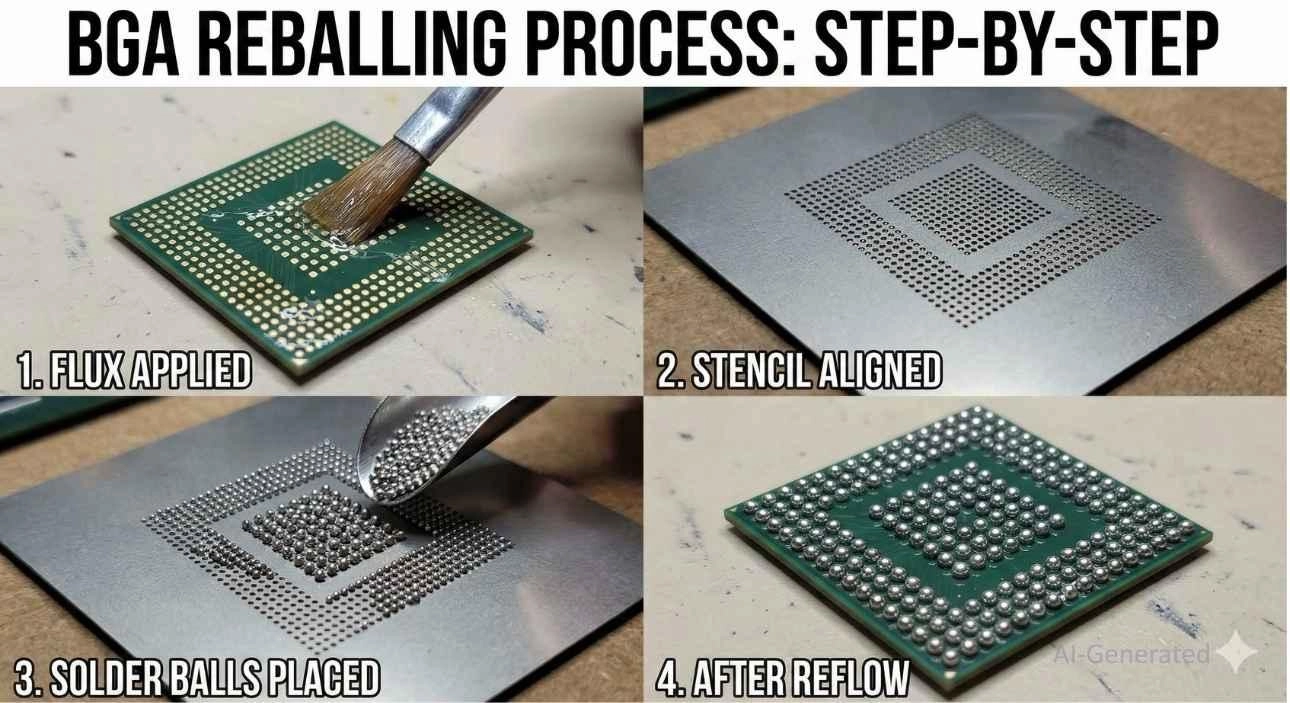
Figure: Applying solder spheres through a BGA reballing stencil.
Step 4: Replacing and Aligning the BGA Chip
The clean PCB pads are prepped with a microscopic, even layer of tacky flux. Using the split-vision optics of a BGA rework machine, the operator overlays the image of the BGA's solder spheres onto the image of the PCB's copper pads, adjusting the X, Y, and Theta axes until they are perfectly aligned.
Step 5: Reflow Soldering
Once aligned, the chip is lowered onto the board. The machine executes the final reflow soldering profile - carefully ramping up the heat to activate the flux, soaking it to equalize temperatures, peaking to melt the solder, and finally initiating cooling fans to solidify the joints and form strong intermetallic bonds.
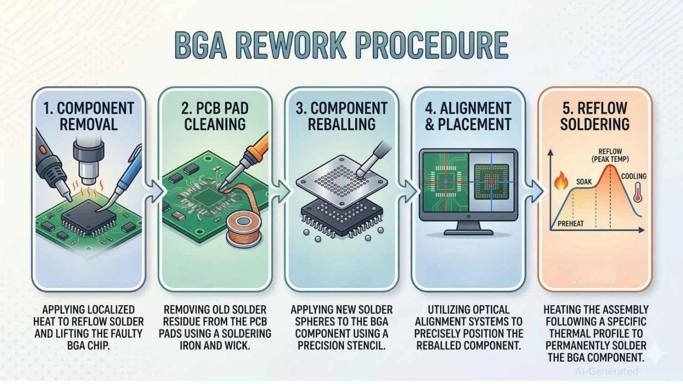
Figure: Step-by-step flowchart of the BGA component rework and reballing process.
BGA Rework Tools and Equipment
Attempting this process with standard handheld tools is a recipe for disaster. Professional repairs require specialized BGA rework tools and machinery. You must invest in high-quality, tacky "no-clean" flux, fresh solder paste, and polyimide (Kapton) thermal tape to protect adjacent connectors.
Additionally, you will need precision titanium tweezers, highly conductive desoldering braid, and precision-machined BGA reballing stencils. Having a deep understanding of the surface mount devices will dictate the specific stencil pitches and sphere sizes you should stock for your workstation.
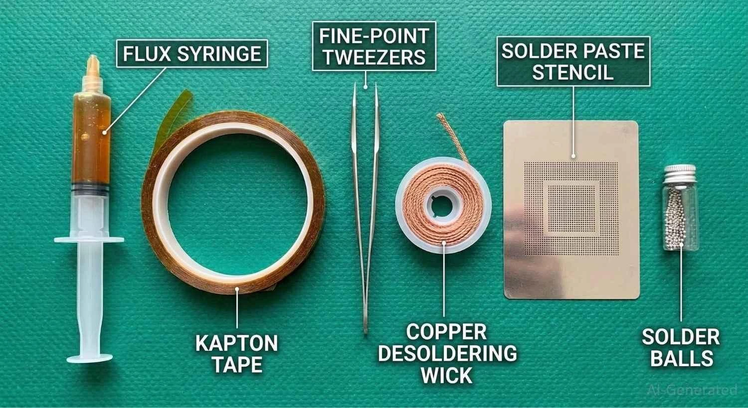
Figure: Essential tools and accessories required for successful BGA rework and reballing.
BGA Rework Machines and Stations
A BGA rework station is the centerpiece of the repair process. It combines a top heater, a large bottom preheater, a rigid PCB mounting fixture, and built-in thermal profiling software. These machines take the guesswork out of thermodynamics, ensuring the board is heated evenly to prevent warping and pad delamination.
Hot Air Rework Tools
Many mid-range rework stations rely on hot air top heaters. These use targeted nozzles that guide heated ambient air directly onto the component. They are highly favored for their rapid heating capabilities and precise, localized temperature control. However, operators must be careful not to set the airflow too high, which could blow away adjacent micro-components, such as 0201 resistors.
Infrared Rework Systems
Infrared (IR) rework equipment uses dark IR emitters to heat the component through electromagnetic radiation rather than moving air. IR systems offer incredibly uniform heat distribution with zero air turbulence, making them ideal for densely packed boards. However, they can struggle to heat highly reflective, silver-capped ICs without specialized thermal tape.
X-ray Inspection Equipment
Because you cannot visually inspect a BGA joint with a microscope, X-ray inspection is mandatory for professional quality control. X-ray machines allow technicians to look through the silicon die to see the shape, size, and density of the solder joints, easily spotting hidden voids or bridges.
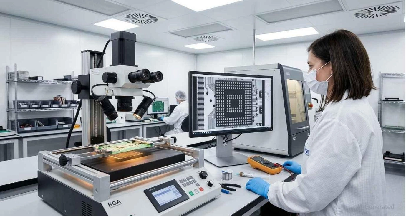
Figure: Professional BGA rework station and X-ray inspection equipment in a laboratory.
BGA Rework vs BGA Reballing
While these terms are often used interchangeably in casual conversation, they describe different scopes of work.
What Is BGA Reballing?
If you are wondering exactly what this sub-process entails, BGA reballing simply means replacing the grid of solder spheres on the bottom of a chip. It is the process of taking a chip with flattened, used solder bumps, cleaning it, and attaching brand-new spheres so it can be mounted to a board again.
For a more detailed breakdown of the chip reballing procedure, see our guide on BGA reballing explained.
Key Differences Between Rework and Reballing
Rework is the umbrella term for the entire repair procedure on the motherboard. It includes diagnosing the fault, removing the chip, cleaning the board, and soldering a component back on.
Reballing is just one specific step that might occur during rework. If you are replacing a dead BGA chip with a brand-new, factory-sealed chip, you are performing rework without reballing.
When to Use Each Method
- Use Reballing: When a highly expensive or out-of-production chip (like a rare GPU or custom ASIC) is physically healthy but was subjected to a bad factory reflow or fractured joints.
- Use Rework (with a new chip): When diagnostic testing proves the internal silicon of the original BGA chip is dead or shorted. In this case, reballing is a waste of time; you must source a new component and rework the board.
Common Challenges in BGA Rework
Even with top-tier BGA rework equipment, technicians face strict physical limitations when manipulating circuit boards.
PCB Pad Damage
The most frequent and devastating challenge is lifted pads. Copper pads are bonded to the FR4 fiberglass using heat-sensitive adhesives. If a technician attempts to lift the chip before all 500+ solder balls are fully molten, or if they aggressively scrape the pads during cleaning, the copper pads will rip off the board, often rendering the PCB unrepairable.
Misalignment During Placement
Modern BGAs have pitches (the distance between ball centers) as small as 0.3mm. Placing a chip manually without optical alignment almost guarantees failure. Even being off by a fraction of a millimeter will cause the molten solder balls to grab the wrong pads during reflow, resulting in massive short circuits.
Solder Voids and Bridging
If the reflow profile ramps up too quickly, the flux paste can violently boil, creating gas pockets trapped inside the molten solder (voids). If too much flux or solder paste is used, the excess material will squeeze outward as the chip settles, causing two adjacent balls to fuse (bridging).
Common Mistakes to Avoid During BGA Rework
Even with top-tier equipment, operator error can ruin a board.
Skipping the Bake Cycle (The "Popcorning" Effect)
Moisture naturally absorbs into the BGA substrate and the PCB’s FR4 material over time. If rapidly heated during rework, this moisture turns to steam, expands, and literally cracks the component open - an effect known as popcorning. Always pre-bake boards.
Using Incorrect Thermal Profiles
Ramping up temperatures too quickly causes thermal shock, which can crack the silicon die. Conversely, soaking the board at high temperatures for too long will cause the copper pads to delaminate and lift away from the fiberglass substrate.
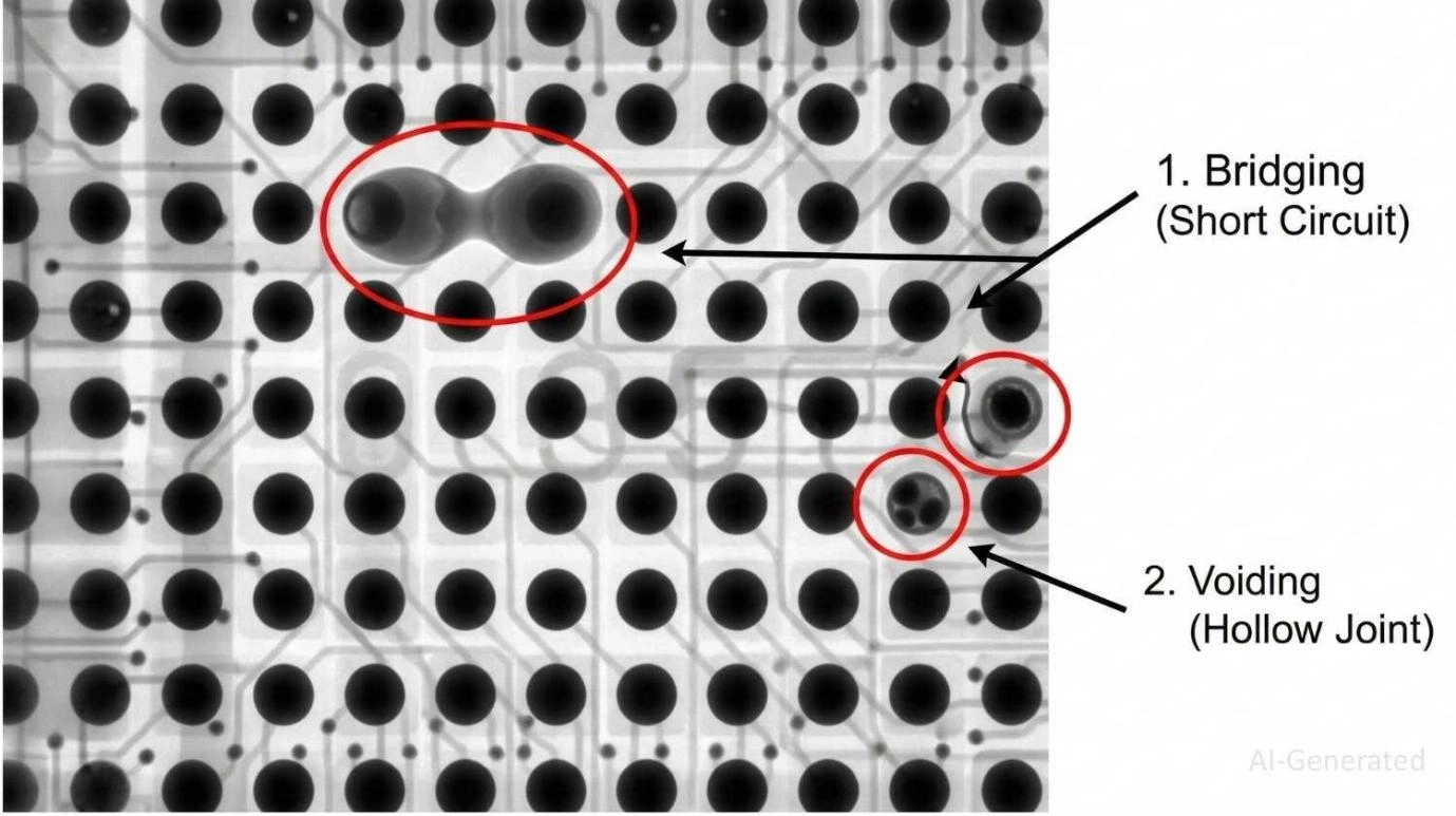
Figure: X-ray view of BGA solder defects, including bridging and voids caused by poor thermal profiling.
Applying Improper Amounts of Flux
Excessive flux will rapidly boil off during reflow, creating gas bubbles that can physically push the BGA off its alignment. Too little flux will fail to remove oxidation, resulting in brittle, cold, or completely open joints.
Forcing the Chip
Never pull or pry the BGA with tweezers. If the chip does not lift effortlessly with the vacuum pen, the solder balls have not fully reached a liquidus state. Forcing it will rip the copper pads right off the PCB, often rendering the board unrepairable.
Overusing Flux in BGA Pad
Believing "more is better," inexperienced technicians flood the site with flux. This causes the chip to literally float and drift off-target during the reflow phase.
Ignoring Component Datasheets
Every chip has a specific thermal limit. Applying a generic heating profile to a highly sensitive memory chip can destroy the silicon die internally.
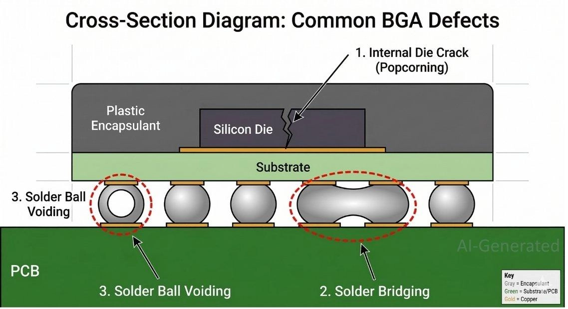
Figure: Cross-section diagram showing common BGA defects like popcorning, bridging, and voiding.
Best Practices for Successful BGA Rework
To achieve factory-level reliability on a repaired board, operators must adhere to strict scientific principles.
Proper Temperature Profiles
A successful rework relies entirely on the thermodynamics of the profile. A standard profile includes a Preheat phase (safely bringing the board up to temperature to activate flux), a Soak phase (equalizing the temperature of the chip and board), a Reflow phase (spiking the heat to reach the liquidus state of the solder alloy), and a Cooling phase. Using external thermocouples to verify these temperatures is essential.
Accurate Component Alignment
Never rely on silkscreen markings for high-density components. Always utilize the split-vision prisms of a professional BGA rework machine to ensure the microscopic spheres align perfectly with the copper pads before the top heater descends.
Using High-Quality Solder Materials
Reworking chemistry is unforgiving. Using cheap, expired, or oxidized materials guarantees failure. Technicians must use specialized, highly viscous "tacky" flux designed to hold the chip in place during heating.
Furthermore, understanding how to use solder paste and high-grade solder spheres ensures strong intermetallic bonding.
Whenever possible, it is recommended to source high-quality replacement parts from a trusted library to avoid installing degraded silicon.
Mitigating BGA Rework with Reliable PCB Assembly
Ultimately, manual rework is a costly symptom. It is incredibly time-consuming, requires highly skilled labor, and inherently introduces secondary thermal stress to the PCB, which can reduce its overall lifespan in the field.
The most effective way to handle BGA rework is to avoid it through superior initial manufacturing actively. Transitioning your projects to low-volume PCB assembly with an industry-leading partner guarantees that BGAs are placed by precise automated machines and validated by advanced 3D X-ray and Automated Optical Inspection (AOI) systems.
By utilizing rigorous turnkey PCB assembly services, you ensure reliable, flawless BGA solder joints straight out of the factory, drastically driving down your failure rates.
When to Choose Professional BGA Rework Services
Not every engineering team needs a $10,000 rework machine. If you are developing prototypes, dealing with highly complex multi-layer server boards, or lack access to X-ray inspection gear, attempting in-house rework is a high-risk gamble.
In these scenarios, outsourcing to professional BGA rework services or simply utilizing advanced turnkey manufacturing is the smartest financial decision. Facilities equipped with automated rework centers can safely replace components with guaranteed yields.
Better yet, ensuring your designs are manufactured flawlessly from day one eliminates this bottleneck. By leveraging JLCPCB's turnkey PCB assembly services, your boards are assembled with micrometer precision and rigorously tested, ensuring your hardware works perfectly right out of the box.
FAQs
Q: Can BGA rework be done with a hot air gun?
Basic BGA removal may be attempted with hot air tools, but reliable BGA rework usually requires controlled heating, board preheating, accurate alignment, and inspection equipment to avoid pad damage or hidden solder defects.
Q: How long should a PCB be baked before BGA rework?
Baking times depend on the board's thickness and the component's Moisture Sensitivity Level (MSL). Generally, baking the assembly at 105°C to 125°C for 4 to 24 hours is required to safely drive out trapped moisture and prevent popcorning during rework.
Q: Can underfilled BGA components be reworked?
Yes, but it is incredibly difficult. Underfill is a hard epoxy injected under the chip to protect it from mechanical shock. Reworking requires carefully heating the board to soften the epoxy and mechanically scraping it away from the chip edges and PCB pads without gouging the solder mask.
Q: Is a nitrogen environment necessary for BGA rework?
While not strictly mandatory for basic repairs, shielding the rework area with nitrogen gas (N2) displaces oxygen. This significantly reduces the oxidation of the copper pads and solder spheres during the high-heat reflow phase, resulting in shinier, stronger solder joints with better wetting characteristics.
Q: What happens if a copper pad is ripped off during chip removal?
If a pad is torn, the board is not necessarily dead, but it requires micro-repair. A technician must use a microscope and a scalpel to expose the remaining copper trace, solder a microscopic copper replacement pad (or wire) to the trace, and secure it with UV-curable solder mask before placing the new BGA.
Q: Can I mix leaded and lead-free solder during a BGA rework?
It is highly discouraged. Mixing RoHS (lead-free) solder spheres with leaded (SnPb) solder paste creates a chaotic metallurgical alloy with unpredictable melting points. This usually results in severe voiding, brittle joints, and premature failure. Always match the alloy of your spheres to the alloy of your paste.
Conclusion
Mastering BGA rework requires a deep understanding of thermodynamics, precise mechanical control, and high-quality BGA rework equipment. While knowing how to safely remove, reball, and replace a BGA chip is an invaluable skill for diagnosing hardware failures, it is a process fraught with risks of thermal damage and pad lifting.
The ultimate goal for any hardware team should be flawless initial design and manufacturing. Ready to bring your complex BGA designs to life without worrying about post-production repairs?
Get an instant quote with JLCPCB today for industrial-grade assembly, precise component placement, and strict X-ray inspection.
Popular Articles
• Common PCB Assembly Methods and Soldering Techniques Explained
• What Is BGA Void? Causes, IPC Limits, and Solutions
• SMD Soldering Tools You Need: Complete Guide from Beginner to Pro
• Reflow Soldering: Everything You Need to Know
• SMT Assembly Process Explained and Equipment Used: A Step-by-Step Guide to PCBA Manufacturing
Keep Learning
12 Professional Soldering Tips and Tricks Every Beginner Should Know
Soldering is not merely "gluing" metal; it is a metallurgical process that creates an intermetallic compound (IMC). This molecular bond ensures the electrical and mechanical integrity of your device. A poor joint might pass a quick visual check but will inevitably fail under vibration or thermal stress, leading to "ghost" bugs and hardware failures. These soldering tips and tricks focus on practical, repeatable techniques used in professional electronics soldering—from correct heat transfer and flux u......
Solder Melting Point Guide: Chart, Alloy Types, and Reflow Considerations
In the precise world of electronics manufacturing, a difference of just a few degrees can mean the distinction between a perfect, reliable solder joint and a catastrophic "cold" joint failure. While many hobbyists view soldering simply as "melting metal to stick things together," professional PCB assembly requires a nuanced understanding of thermodynamics. The solder melting point is not simply a single value listed in a datasheet; it is a decisive limit that determines the choice of components, the s......
The Ultimate Guide to Solder Flux: Everything You Should Know Before Soldering PCB
Soldering is needed to make almost all electronic devices. Adding solder alone won't make a joint that is strong, clean, and sound from a metallurgical point of view. Solder flux is a very important part of the process that comes in here. If you want to do your job better and make it more reliable, you need to know a lot about soldering flux, whether you're an engineer, a professional technician, or just a hobbyist. This article goes into a lot of detail about solder flux, including what it is, how it......
Common PCB Assembly Methods and Soldering Techniques Explained
Whether you're designing your first prototype or scaling up to production, understanding PCB assembly methods and soldering techniques is crucial to achieving reliable, high-performance circuit boards. Modern PCBA primarily relies on Surface Mount Technology (SMT) and Through-Hole Technology (THT)—each offering unique advantages for component density, durability, and manufacturability. In this guide, we'll break down the major PCB assembly methods, key soldering techniques such as reflow and wave sold......
Flex PCB Assembly Guide: Process, Challenges, and Solutions
Flexible Printed Circuit Boards (Flex PCBs) are the foundational technology enabling the compact, innovative design of modern electronics. Because of their ability to bend and fold, they power devices from smart wearables to compact medical instruments where traditional rigid printed circuit boards (Rigid PCBs) can't be used. Achieving a functional electronic circuit from the raw plastic film demands special expertise, with flexible PCB assembly (FPCA) representing the crucial final step in this trans......
SMD Rework Guide: Tools, Temperatures, and Techniques That Prevent PCB Damage
From replacing a burned regulator to correcting wrong component values or removing solder bridges on fine-pitch ICs, SMD rework is an essential skill in electronics manufacturing and prototyping. It allows engineers to repair assembly defects, implement design changes, and recover valuable PCBs without the cost and delay of building new boards. In this guide, you will learn: What SMD rework is Common rework scenarios Tools and temperatures Safe removal and installation Package-specific techniques Real......