Cooling Induction Power Supplies: Designing the Thermal System That Protects Your Electrical System
10 min
- What Typically Needs Cooling (and Why It's Not Optional)
- Steady State Beats Warm-Up: The Duty-Cycle Trap
- Cooling Architecture Options
- Comparison Table: Cooling Choices in Practice
- Instrumentation That Prevents Nuisance Trips
- Why Branch Balancing Is a Common Hidden Failure
- A Practical Troubleshooting Sequence
- Cooling as a Specification: Make It Measurable
- Cooling and Electrical Performance: The Feedback Loop You Can't Ignore
- Maintenance Strategy: Stock the Boring Spares
- A Commissioning Baseline That Enables Trending
- When Cooling Becomes a Production KPI
- Heat Rejection Sizing: Why You Need a Realistic Loss Estimate
- Water Chemistry and Conductivity: Protecting Cold Plates and Capacitors
- From Reactive to Predictive Maintenance
- Designing the Cooling Loop as a System (Not as Plumbing)
- Short Checklist After Maintenance
- Water Quality Requirements Are Topology-Dependent
- Cooling with Process Fluids: When It Makes Sense
- Cooling Limits as Operating Limits
- FAQ about Cooling Induction Power Supplies
Key Takeaways
Cooling is a first-class subsystem: Many "electrical" failures in induction lines are actually thermal problems—drifting water temperature, clogged filters, or unbalanced branch flow.
Measure at the branch, not the header: A healthy header can mask a starved branch. Branch flow to the highest-loss modules is the single most useful cooling measurement.
Trend cooling like a process variable: Baseline flow, temperature, and filter pressure drop during commissioning, then trend them to turn emergency downtime into scheduled maintenance.
Specify measurable criteria: Minimum branch flow and maximum inlet temperature at rated power prevent commissioning disputes and create objective acceptance standards.
Water quality is topology-dependent: Cooling water chemistry is part of the electrical design—changing it without understanding topology assumptions can create safety hazards.
What Typically Needs Cooling (and Why It's Not Optional)
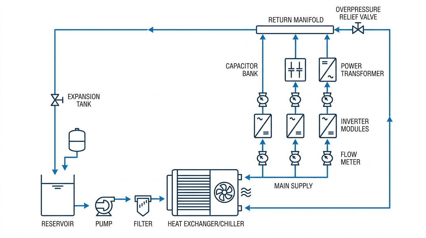
Cooling loop schematic.
Depending on topology and power level, water cooling may be used for inverter modules, capacitor banks, transformers, buswork, and sometimes coil leads. Even when some parts are air-cooled, cabinet airflow and filtration become critical in dusty environments.
The key point is that cooling is not a utility afterthought. Semiconductor loss, capacitor loss, transformer loss, and bus losses become heat that must be removed continuously at duty cycle.
Steady State Beats Warm-Up: The Duty-Cycle Trap
A short successful trial run is not proof of continuous capability. Water-cooled modules stabilize quickly; large structures may take hours. If you commission at reduced time or reduced power, you may miss the thermal condition that triggers drift or trips during production.
Cooling Architecture Options
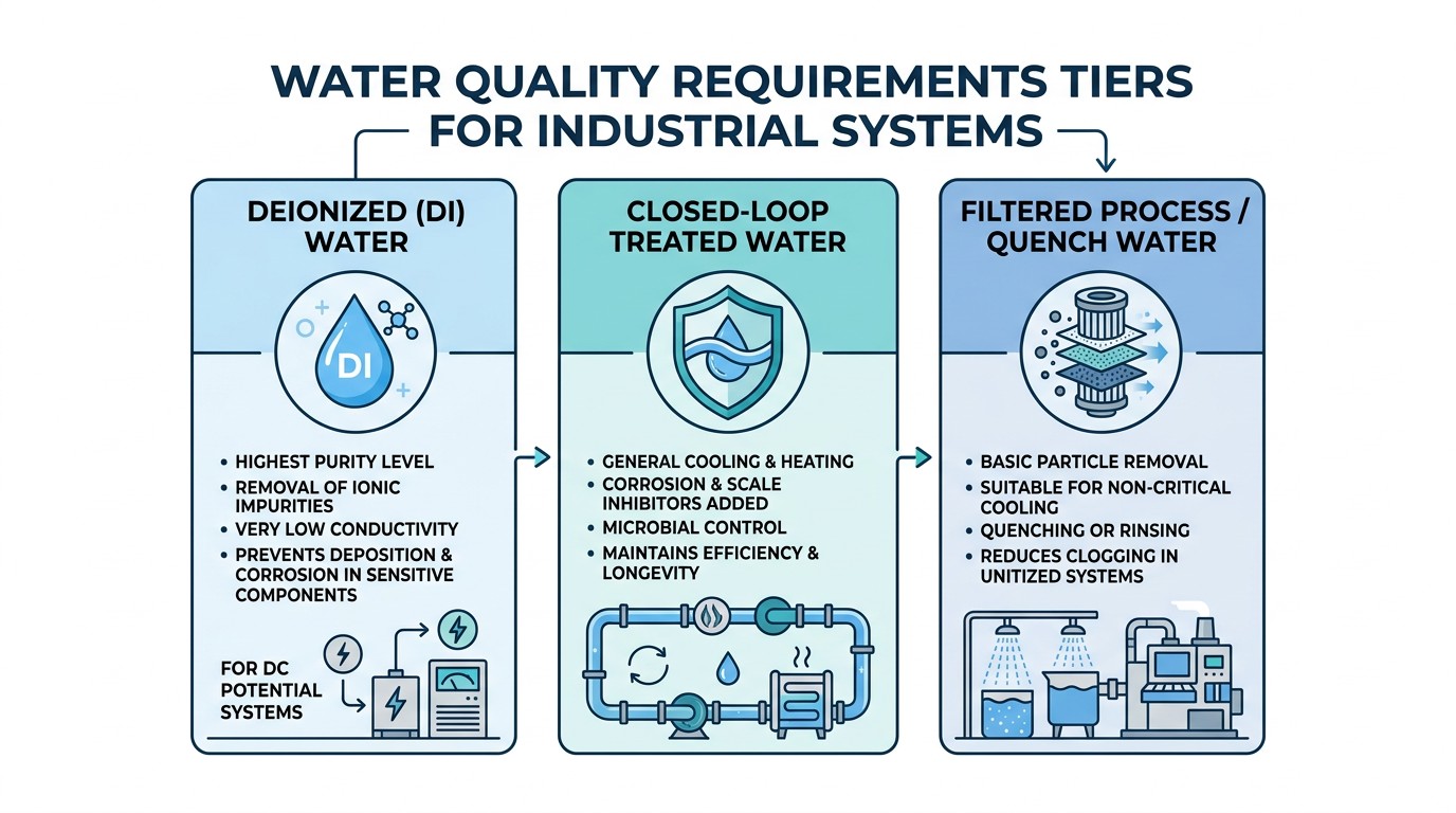
Water quality tiers and when each is typically required.
Direct plant water can be simple but variable. Closed-loop heat exchanger packages improve water chemistry stability and reduce scaling in cold plates. Chiller-based systems can provide tight temperature control in high ambient conditions.
The right choice depends on your inlet temperature range, water quality, and how critical uptime is.
Comparison Table: Cooling Choices in Practice
| Architecture | Strength | Common Risk |
|---|---|---|
| Plant water direct | Simple, low capital | Variable temperature/chemistry |
| Closed loop + heat exchanger | Stable chemistry, cleaner | Requires proper heat rejection sizing |
| Chiller-based | Tight temperature control | Higher energy/maintenance burden |
Instrumentation That Prevents Nuisance Trips
Flow switches alone often fail to diagnose drift. Flow meters, inlet/outlet temperature sensors, and filter differential pressure monitoring turn cooling from "mystery trips" into scheduled maintenance.
Just as importantly, measure flow by branch. A header can look fine while one branch is starved.
Why Branch Balancing Is a Common Hidden Failure
Many cooling systems look fine at the header but fail at the branch level. A partially clogged filter, a kinked hose, or trapped air can starve one module while other branches remain healthy. The first symptom is often an inverter trip that looks electrical.
Design cooling with serviceability: isolation valves, purge points, and instrumentation where it matters. Then trending becomes possible, and you can fix the problem before it becomes downtime.
A Practical Troubleshooting Sequence
-
Check Inlet Conditions
When a cooling alarm occurs, check inlet temperature and header pressure first.
-
Verify Branch Flow
Then verify branch flow to the affected module.
-
Inspect Filters and Strainers
Inspect filters and strainers and record differential pressure if available.
-
Verify Sensors
Finally, verify sensors—failed flow switches can mimic real loss of flow.
Note
Structured troubleshooting beats repeated resets.
Cooling as a Specification: Make It Measurable
To avoid commissioning disputes, specify minimum branch flow, maximum inlet temperature, maximum allowed temperature rise across key modules, and alarm/shutdown behavior. Measurable criteria prevent ambiguous "it should be fine" arguments.
Cooling and Electrical Performance: The Feedback Loop You Can't Ignore
As components heat, resistances change and switching losses can increase. That means cooling drift can create electrical drift, which then creates thermal drift—a feedback loop. In marginal systems, this loop shows up as gradually increasing current for the same kW, or as trips late in a long run even though startup looked fine.
Breaking the loop is straightforward: maintain stable inlet temperature, maintain branch flow, and keep heat exchangers clean. The challenge is organizational, not technical—cooling must be owned and monitored like a production-critical subsystem.
Maintenance Strategy: Stock the Boring Spares
Most cooling failures are not exotic. They are clogged filters, worn pump components, failing sensors, or degraded hose fittings. Stocking filters, common sensors, and hose/fitting kits prevents long downtime for simple issues.
A Commissioning Baseline That Enables Trending
During commissioning, record branch flow, inlet and outlet temperatures, and key module temperatures at a standardized operating point. Store those numbers. If performance drifts later, you have a factual reference rather than a debate.
When Cooling Becomes a Production KPI
In high-duty induction environments, cooling performance deserves the same attention as throughput and scrap. If you track branch flow, inlet temperature, and filter differential pressure, you can predict many failures days or weeks in advance. Plants that treat cooling as a KPI typically experience fewer unexplained inverter trips and longer component life.
Heat Rejection Sizing: Why You Need a Realistic Loss Estimate
Cooling systems are often undersized because teams estimate losses optimistically. A simple sizing approach is to estimate losses from efficiency: if the system delivers Pout at efficiency η, then loss is Pout(1/η − 1). Even a small loss fraction becomes large at high power.
Then convert that loss into required coolant flow based on allowable temperature rise. If you are unsure, design with margin and verify during commissioning. Undersized cooling produces intermittent faults that waste far more time than the cost of a larger heat exchanger.
Water Chemistry and Conductivity: Protecting Cold Plates and Capacitors
Water quality affects corrosion, scaling, and leakage paths. In high-voltage environments, conductivity can also matter for safety and for insulation risk. If plant water is variable, closed-loop systems with controlled chemistry often provide better long-term stability.
From Reactive to Predictive Maintenance
Cooling systems are a perfect target for predictive maintenance because drift is slow and measurable. If you log filter differential pressure and branch flow, you can schedule maintenance before the line trips. This is one of the most cost-effective reliability practices in induction installations.
Environmental Note: Dust and Airflow Still Matter
Even water-cooled systems rely on cabinet airflow for some components and for keeping electronics within ambient limits. In dusty environments, filtration and cabinet sealing are part of the cooling design.
Designing the Cooling Loop as a System (Not as Plumbing)
A cooling loop that is treated as generic plumbing will eventually create electrical downtime. Treat it as a designed system with known pressure drops, balanced branches, and maintainable instrumentation. The goal is to deliver predictable flow to each critical component under all plant conditions.
That usually means designing manifolds and branch restrictions intentionally, not as an afterthought. It also means providing purge points so air can be removed after maintenance. Air trapped in high points can reduce effective flow and create intermittent alarms.
In high-duty lines, consider redundancy: standby pumps, parallel filters, or at least a bypass path that allows controlled operation while maintenance is performed. Even if full redundancy is not justified, designing for fast repair is.
From a documentation standpoint, include a simple cooling schematic in the maintenance package and label branches clearly. Many long downtimes happen because technicians are unsure which valve affects which module.
Commissioning Tip: Verify Flow at the Actual Machine
Many cooling issues come from assuming header measurements represent branch reality. During commissioning, measure flow and temperature rise at the machine branches that feed the inverter, capacitors, and transformer. Store those values as your baseline.
Short Checklist After Maintenance
- Purge air from all cooling branches
- Verify branch flow to each critical module
- Confirm inlet temperature is within specification
- Check pressure drop across filters
Note
A five-minute checklist prevents many post-maintenance nuisance trips.
Water Quality Requirements Are Topology-Dependent
Cooling hardware context.
A key detail is that water quality requirements vary with power supply type and application. In vacuum tube oscillators and some SCR-based supplies, there can be DC voltage potential between water-cooled power components. That condition can require distilled and deionized water to control conductivity and reduce electrical risk.
In other designs, quench water (even filtered quenchant) may be used successfully for cooling. The point is not that one approach is always better; the point is that cooling water is part of the electrical design. If you change water chemistry or conductivity without understanding the topology assumptions, you can create safety hazards or accelerate corrosion and scaling.
This is why a cooling specification should include not only flow and temperature, but also water quality targets. It also explains why some vendors provide closed-loop systems designed to maintain water chemistry, especially where DC potentials exist.
Cooling with Process Fluids: When It Makes Sense
Long-running service examples show that quench fluid has been used as coolant in certain unitized heat-treating systems. This can be attractive operationally—one fluid system rather than two—but it requires careful filtration and an understanding of what components are sensitive to conductivity. If you plan to share process fluids with cooling, treat filtration and monitoring as production-critical.
Cooling Limits as Operating Limits
A practical mindset shift is to treat cooling limits as operating limits. If inlet temperature rises, allowable continuous kW may drop. If filter pressure drop rises, branch flow may fall, and allowable ramp rates may need to be reduced temporarily. Some plants encode these relationships directly into interlocks or alarms so the station de-rates gracefully instead of tripping unexpectedly.
Even when you don't implement automatic de-rating, documenting cooling-related operating limits helps operators and maintenance teams respond correctly. It also prevents a common failure mode: chasing electrical parameters when the true root cause is a shrinking thermal margin.
The Most Common Commissioning Oversight
A frequent oversight is to validate cooling at a single power level and assume linearity. In reality, losses can rise disproportionately with current and with circulating reactive power, especially when the tank is detuned or when multiple branches share a manifold. Validate cooling under the operating points that maximize RMS current and tank voltage—not only under the point that maximizes delivered kW.
Safety Reminder: DC Potentials and Water Handling
Where DC potentials can exist across water-cooled components, treat water handling as an electrical safety topic. Verify conductivity targets, maintain deionization where required, and ensure leak detection and safe shutdown procedures are documented and tested.
Conclusion: Cooling Induction Power Supplies
Cooling is one of the few subsystems where simple trending (flow, temperature, pressure drop) can prevent most failures. If you implement that trending, many "electrical" reliability problems disappear.
If your site water temperature varies seasonally, record summer and winter baselines. A cooling loop that is stable in winter can become marginal in summer, and seasonal baselines make that drift obvious.
Measure and record pressure drop across filters; it is often the earliest and most reliable indicator that cooling margin is about to disappear.
If you see repeated summer-only trips, treat inlet temperature control as a project, not a nuisance. Adding a chiller or improving heat rejection often pays back quickly. It's usually cheaper than downtime.
FAQ about Cooling Induction Power Supplies
Q: Why do cooling trips become more common after months of operation?
Filters load, pumps drift, heat exchangers foul, and scaling accumulates. The system slowly loses margin until it crosses an alarm threshold.
Q: What's the single most useful cooling measurement?
Branch flow to the highest-loss modules. Header readings can hide a partially blocked branch.
Q: What two specification numbers prevent many disputes?
Minimum flow per branch and maximum inlet temperature at rated power. These create objective acceptance criteria.
Keep Learning
Induction Billet Heating: How to Achieve Uniform Heating
Induction billet heating prepares metal for forging, extrusion, or rolling by generating heat inside the workpiece. For steel billets, reaching the required exit temperature is only part of the task: the temperature distribution from surface to core and along the billet must also suit the forming process. Uniformity depends on how frequency, coil geometry, heat transfer, power distribution, and billet movement work together. This guide focuses on through-heating steel billets, particularly in progress......
How to Upgrade a 3D Printer Heated Bed with a Silicone Heater
If your 3D printer heated bed takes too long to reach temperature, develops uneven heating, or struggles to maintain a stable surface temperature, a silicone heater can be a practical upgrade. Faster warm-up and more uniform heat can improve first-layer consistency and reduce temperature-related printing issues. This guide explains how to identify when a heated-bed upgrade is needed, choose a suitable silicone heater, install it safely, and verify the results. Quick Answer A silicone heater can be a s......
How Graphene and MXene Flake Sensors Detect Force
Key Takeaways Flake networks sense force through microstructural change: Graphene and MXene coatings distribute conduction across overlapping platelets whose contacts shift under stretch or pressure, producing measurable resistance changes. Three mechanisms compete: Crack propagation, flake slippage, and quantum tunnelling each dominate at different deformation levels, giving many sensors multiple sensitivity regions rather than one uniform response. The substrate is an active partner: Elastomers, tex......
Conductive 2D Coatings Are a Matching Problem, Not a Miracle Ink
Key Takeaways Ink is a system, not a material: Conductivity depends on the combined effect of flake chemistry, solvent, additives, substrate, coating method, and post-processing—not on the 2D filler alone. Three carbon routes carry different trade-offs: GNPs demand dispersion engineering, GO shifts effort to a reduction step, and MXenes move the bottleneck to synthesis, storage, and oxidation control. Substrate geometry drives method selection: Spray and blade coating suit flat sheets; dip coating nat......
Graphene Heat Spreader Design: Layers and Interfaces
Key Takeaways Conductivity alone is not enough: A record thermal-conductivity value does not guarantee a cooler chip. Effective thickness, interface resistance, hot-spot geometry, and heat-sink connections all belong to the same thermal path. Few-layer graphene can outperform a single layer in practice: A few-layer sheet provides a larger heat-flow cross section and better tolerates transfer, embedding, and defects, even though its intrinsic conductivity is lower. Interface resistance is the bottlenec......
How Graphene Heat Spreaders Cool SOI Chip Hot Spots
Key Takeaways Buried oxide is a thermal bottleneck: SOI's insulating layer improves electrical isolation but traps heat near transistor channels, creating dangerous hot spots that package-level cooling alone cannot fix. Graphene enables lateral heat routing: Placing graphene or few-layer graphene beneath the buried oxide adds a high-conductivity sideways path, redistributing hot-spot energy toward dedicated sinks without removing any heat itself. Multi-source chips benefit most: Finite-element modelin......