
Arduino LED Multiplexing Tutorial: Control More LEDs with Fewer Pins
17 min
- What Is Arduino LED Multiplexing?
- Arduino LED Multiplexing Techniques Compared
- How to Build an Arduino 8x8 LED Matrix
- How to Implement Arduino LED Charlieplexing
- Arduino LED Multiplexing Troubleshooting
- Practical Arduino LED Multiplexing Projects
- Conclusion
- FAQs about Arduino LED Multiplexing
The Arduino Uno is a powerful tool for prototyping, but driving multiple LEDs directly quickly exhausts its 20 GPIO pins and its 200 mA absolute maximum package current limit. To bypass these hardware bottlenecks, engineers and hobbyists use LED multiplexing to scale display outputs efficiently without upgrading the microcontroller.
In this guide, you will learn the core principles of LED matrix scanning, Charlieplexing, refresh timing, ghosting fixes, and practical Arduino code without relying on any external driver or expansion ICs.
What Is Arduino LED Multiplexing?
Arduino Uno GPIO Limits Explained
Every GPIO pin on an ATmega328P-based Arduino Uno has strict electrical limitations.
- Absolute Maximum: A single GPIO pin can source or sink up to 40 mA under peak, non-continuous conditions.
- Recommended Limit: The safe operating limit for continuous output is 20 mA or less per pin.
- Total Package Limit: Crucially, the total combined current passing through the chip’s VCC and GND pins must not exceed 200 mA.
Trying to drive a 4x4 array of 16 LEDs directly at 15 mA each would demand 240 mA, risking permanent thermal damage to the silicon.
Warning:
NEVER connect an LED directly to a microcontroller pin without a current-limiting resistor. Doing so will cause excessive current draw, risking immediate burnout of the LED or the Arduino itself.
Persistence of Vision in LED Multiplexing
LED multiplexing relies on a physiological phenomenon known as Persistence of Vision (PoV). The human eye cannot perceive changes in light intensity that occur faster than approximately 50 to 100 Hz (a period of 10 to 20 milliseconds).
If an LED is turned on for 1 millisecond and then off for 9 milliseconds, and this cycle repeats continuously, the eye integrates the light pulses. Instead of seeing a flashing light, we perceive a continuous, slightly dimmer light. By cycling through a series of LEDs sequentially at high speed, they all appear to be illuminated simultaneously, resulting in a stable display.
Direct Drive LED vs Multiplexed Array
There are two primary ways to drive LEDs directly using native microcontroller pins:
- Direct-Drive: Connecting one LED to one dedicated GPIO pin through a current-limiting resistor. While simple to code, it scales poorly, consuming one full pin per light source and hitting the chip's total package current limit very quickly.
- Multiplexed Scanning: Arranging LEDs in an electrical grid or a specialized configuration (like Charlieplexing). Pixels share physical connections, meaning the microcontroller rapidly switches specific lines over time to address individual coordinates using a fraction of the pins.
Arduino LED Multiplexing Techniques Compared
The tables below outline the core trade-offs of direct-pin LED expansion techniques.
| Technique | Pins Required (for 64 LEDs) | CPU Overhead | Hardware Complexity | Peak Current Stress | Best Use Case |
|---|---|---|---|---|---|
| Direct-Drive | 64 (Not possible on Uno) | None | Very Low | None | Few status indicators |
| Row-Column Matrix Scanning | 16 (8 Rows + 8 Cols) | High | Medium | High (Shared Pin Sourcing) | Standard grid displays, symbols |
| Charlieplexing Array | 9 Pins (Nx(N-1)) | High | High | Very High | Low-power wearables, badges |
Row-Column Matrix Scanning: 16 Pins Drive 64 LEDs
Matrix scanning arranges LEDs in a grid of intersecting rows and columns. By structuring 64 LEDs as an 8x8 grid, we connect all the anodes in each row and all the cathodes in each column. We only need 16 pins to address every single pixel individually, reducing the physical pin requirements by 75% and simplifying your Arduino LED matrix scanning logic.
Arduino LED Charlieplexing
Charlieplexing is an advanced multiplexing method that exploits the tri-state logic of microcontroller GPIO pins (HIGH, LOW, and high-impedance INPUT). By placing LEDs in anti-parallel pairs, Charlieplexing scales efficiently, allowing N pins to drive N * (N - 1) LEDs.
LED Matrix vs Charlieplexing
- Pin Efficiency: Charlieplexing is significantly more pin-efficient. While an 8x8 row-column matrix requires 16 pins to drive 64 LEDs, Charlieplexing requires only 9 pins to achieve a similar capacity (driving up to 72 LEDs).
- Firmware Complexity: Standard row-column scanning only requires switching pins between binary HIGH and LOW states. Charlieplexing requires changing pin directions dynamically between outputs and high-impedance inputs inside the core execution loop.
Choosing the Right Multiplexing Method
Select Row-Column Matrix Scanning if you need consistent brightness, easier routing, and a standard grid alignment. Choose Charlieplexing if your project has severe physical pin constraints, such as a tiny wearable design, and can tolerate a lower overall display duty cycle.
How to Build an Arduino 8x8 LED Matrix
An 8x8 matrix is the ideal starting point for learning grid-based control.
Common-Anode vs Common-Cathode LED Matrix
Because an 8x8 LED matrix is a grid of intersecting diodes, every matrix is physically both common-anode and common-cathode simultaneously, depending on which axis you analyze. The manufacturer’s retail designation specifically refers to the polarity configuration of the Rows:
- Row Common-Anode (Column Common-Cathode): All LEDs in a given row share their anodes (positive), while the columns connect to the shared cathodes (negative). To illuminate a pixel (e.g., Row 1, Column 1), you must pull Row 1 HIGH (source) and Column 1 LOW (sink).
- Row Common-Cathode (Column Common-Anode): All LEDs in a given row share their cathodes (negative), while the columns connect to the shared anodes (positive). To illuminate a pixel, you must pull Row 1 LOW (sink) and Column 1 HIGH (source).
Arduino LED Matrix Wiring Diagram
Below is a conceptual wiring layout for a standard Row Common-Anode (Column Common-Cathode) 8x8 Arduino LED matrix driven directly by an Arduino.
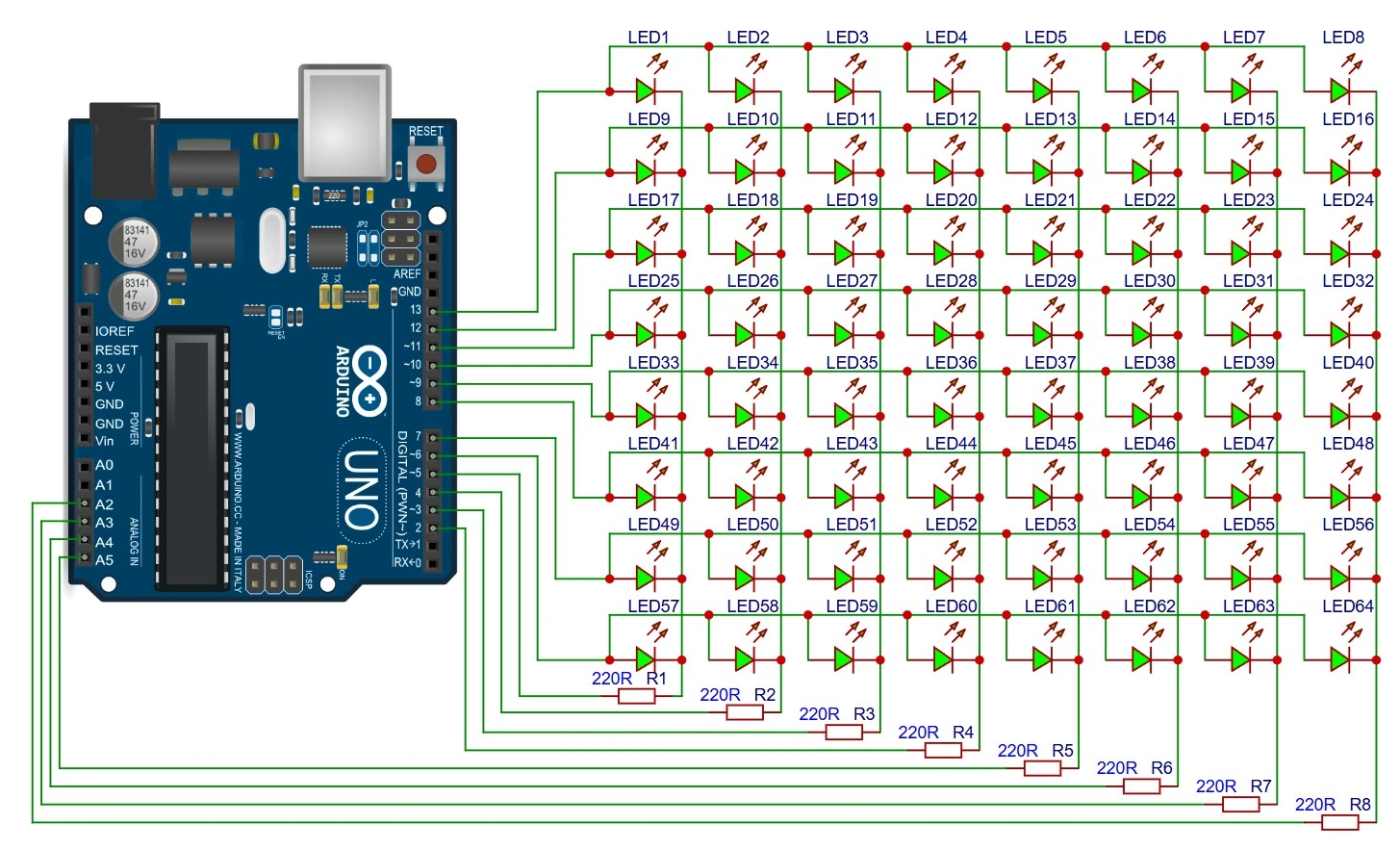
Figure: Schematic diagram of an 8x8 Row Common-Anode (Column Common-Cathode) LED matrix connected to an Arduino Uno, showing row pins connected to anodes and column pins connected to cathodes via resistors.
LED Matrix Resistor Placement
You must place current-limiting resistors on the columns rather than the rows (or vice versa, depending on which axis is being scanned).
- Why it matters: If you place resistors on the rows and scan by row, the brightness of the LEDs will change depending on how many LEDs in that row are turned on. If only 1 LED is active, it will be bright; if all 8 are active, the current is divided, making them very dim.
- The fix: Place one resistor per independently driven row or column line. Depending on the scanning axis (row scanning vs. column scanning), this ensures consistent current distribution and prevents uneven brightness, as the available current is shared across active LEDs.
Use this basic formula to calculate the resistor value:

For a standard 5V supply, refer to the table below for quick calculation values:
| LED Color | Typical V_forward | Suggested Resistor @ 5V (for ~15 mA) |
|---|---|---|
| Red | 2.0V | 220 ohms |
| Green | 2.2V | 220 ohms |
| Blue | 3.2V | 120 ohms |
| Yellow | 2.1V | 220 ohms |
Warning:
Pulse currents must remain strictly within LED datasheet limits. While pulsed duty cycles allow higher peak currents, writing buggy code that stops scanning while high current is active can quickly burn out your LEDs.
Arduino LED Matrix Refresh Rate Calculation
To achieve a stable display with visible flicker elimination, the matrix must be scanned completely at least 60 times per second (60 Hz). A rate of 100 Hz to 200 Hz is preferred for smooth refresh performance. Higher refresh rates may be required to avoid rolling-shutter flicker on smartphone cameras.
| Matrix Size | Scanning Method | Minimum Refresh Rate | Target Refresh Rate | Active Time per Row/Col |
|---|---|---|---|---|
| 4x4 |
Row-by-Row
(4 steps) |
60 Hz | 100 Hz | 2.50 ms |
| 8x8 |
Row-by-Row
(8 steps) |
60 Hz | 100 Hz | 1.25 ms (1250 us) |
| 16x16 |
Row-by-Row
(16 steps) |
80 Hz | 200 Hz | 0.31 ms (312 us) |
For an 8-row matrix scanned one row at a time at 100 Hz:
Total Frame Period = 1 / 100 Hz = 10 ms
Active Time per Row = 10 ms / 8 rows = 1.25 ms (1250 microseconds)
The Arduino must switch rows every 1.25 milliseconds.
Arduino 8x8 LED Matrix millis() Code
Using non-blocking millis() or micros() timing is crucial so the Arduino can handle other tasks, such as sensor reading or serial communication, while updating the display.
Code Highlights:
- Initializes rows and columns: Sets pin directions and baseline off-states during setup().
- Uses non-blocking micros(): Runs a low-overhead scheduler that triggers refresh states based on elapsed time rather than using blocking delay().
- Updates one row per scan cycle: Selectively pulls rows HIGH and active columns LOW, shifting row-by-row on every tick.
// Global Variables and Pattern Definitions
const int rowPins[8] = {13, 12, 11, 10, 9, 8, 7, 6};
const int colPins[8] = {5, 4, 3, 2, A5, A4, A3, A2};

byte heartPattern[8] = {
  B00000000,
  B01100110,
  B11111111,
  B11111111,
  B11111111,
  B01111110,
  B00111100,
  B00000000
};

unsigned long lastScanTime = 0;
const unsigned long scanInterval = 1250;
int currentRow = 0;// Setup Function
void setup() {
for (int i = 0; i < 8; i++) {
pinMode(rowPins[i], OUTPUT);
pinMode(colPins[i], OUTPUT);
digitalWrite(rowPins[i], LOW);
digitalWrite(colPins[i], HIGH);
}
}// Main Loop
void loop() {
unsigned long currentMicros = micros();
if (currentMicros - lastScanTime >= scanInterval) {
lastScanTime = currentMicros;
digitalWrite(rowPins[currentRow], LOW);
for (int col = 0; col < 8; col++) {
digitalWrite(colPins[col], HIGH);
}
currentRow = (currentRow + 1) % 8;
for (int col = 0; col < 8; col++) {
if (bitRead(heartPattern[currentRow], 7 - col) == 1) {
digitalWrite(colPins[col], LOW);
}
}
digitalWrite(rowPins[currentRow], HIGH);
}
}The standard digitalWrite() function used above is simple and excellent for educational clarity, but it is relatively slow. Every call to digitalWrite() performs numerous runtime safety checks (checking if the pin is PWM-enabled, parsing lookup tables for port registers, etc.), which consume up to 4 microseconds of processing time.
Advanced, performance-critical projects often bypass this by using direct port manipulation (e.g., writing PORTD |= B00000100; which executes in a single clock cycle—only 62.5 nanoseconds on a 16 MHz microcontroller) or using hardware timer interrupts to achieve optimal scan efficiency.
Arduino LED Matrix Current Consumption
When designing a multiplexed display, you must balance peak current against average current.
- Peak Current: The maximum current drawn when a row or column is fully turned on. If 8 LEDs are on in a column, the driver circuit must handle this cumulative surge.
- Average Current: Because of the active duty cycle (e.g., 1/8th of a frame in an 8x8 matrix), the average power consumption of a single LED is much lower than when it is continuously driven.
- USB Current Limits: A standard computer USB 2.0 port limits supply current to 500 mA. Large Arduino LED matrix projects often exceed USB power limits. When powering your multiplexed arrays directly over USB, ensure your combined peak currents, including the Arduino's internal overhead (~50 mA), stay well under this threshold to prevent port resets.
How to Implement Arduino LED Charlieplexing
Charlieplexing is a highly efficient way to address a large array of LEDs with minimal pins, but it requires precise control of your pin states.
Tri-State GPIO Logic for Charlieplexing
A standard microcontroller pin has three states: HIGH (5V), LOW (0V), and INPUT. When configured as an INPUT, the pin enters a high-impedance (Hi-Z) state, acting as an open circuit. Charlieplexing takes advantage of this state to isolate specific pairs of LEDs. Any pin not actively driving the current frame is set to an input state to block current flow.
Charlieplexing LED Count Formula
The maximum number of LEDs you can drive with N pins is calculated as:
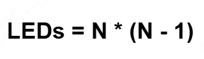
This mathematical scaling is highly efficient. For example, while 3 pins control only 6 LEDs, a slight increase to 6 pins allows you to drive up to 30 LEDs.
The table below highlights how rapidly output scaling increases as you add pins:
| Control Pins (N) | Maximum LEDs | Unused Pins in High-Z State |
|---|---|---|
| 3 | 6 | 1 |
| 4 | 12 | 2 |
| 5 | 20 | 3 |
| 6 | 30 | 4 |
| 10 | 90 | 8 |
Charlieplexing Wiring Diagram
To understand how Charlieplexing operates, it is helpful to visualize the schematic layout of the anti-parallel LED configurations. Below is a visual representation of three pins controlling a six-LED Charlieplexed node:
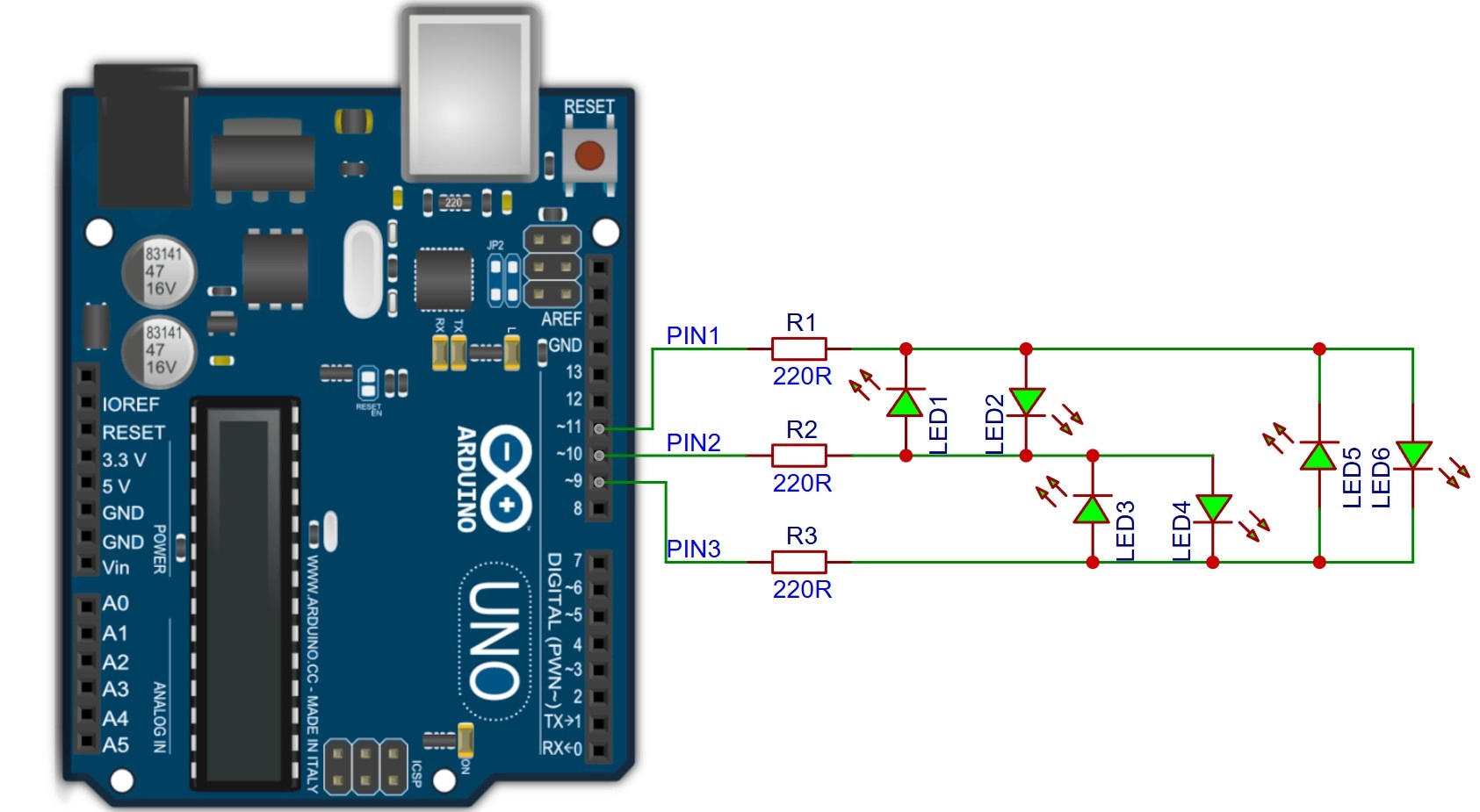
Figure: Charlieplexing circuit diagram with 3 Arduino pins controlling 6 LEDs in anti-parallel pairs, showing resistors on each pin branch.
Arduino Charlieplexing pinMode() Code
Driving a single LED requires setting its source pin to OUTPUT HIGH, its sink pin to OUTPUT LOW, and all other pins to INPUT (Hi-Z).
Code Highlights:
- Clears previous active pins: Iterates through pins, resetting them to INPUT to ensure no stray paths remain active.
- Sets source and sink dynamically: Reconfigures directions and states using a switch-case state machine matching the targeted LED.
// Pin Definitions
const int pins[3] = {9, 10, 11};// turnOnLED() Helper Function
void turnOnLED(int ledIndex) {
for (int i = 0; i < 3; i++) {
pinMode(pins[i], INPUT);
digitalWrite(pins[i], LOW);
}
switch(ledIndex) {
case 1:
pinMode(pins[0], OUTPUT); digitalWrite(pins[0], HIGH);
pinMode(pins[1], OUTPUT); digitalWrite(pins[1], LOW);
break;
case 2:
pinMode(pins[1], OUTPUT); digitalWrite(pins[1], HIGH);
pinMode(pins[0], OUTPUT); digitalWrite(pins[0], LOW);
break;
case 3:
pinMode(pins[1], OUTPUT); digitalWrite(pins[1], HIGH);
pinMode(pins[2], OUTPUT); digitalWrite(pins[2], LOW);
break;
}
}// Setup
void setup() {}// Main Loop
void loop() {
for (int i = 1; i <= 3; i++) {
turnOnLED(i);
delay(5);
}
}Charlieplexing Brightness Limitations
Because Charlieplexing can only light one LED at a time in its standard implementation, the duty cycle of any single LED drops significantly as you add more LEDs. If you are driving 30 LEDs, each LED is active for at most 1/30th of the scan frame. This low duty cycle causes the display to look noticeably dim.
Charlieplexing Ghosting Fix
Ghosting occurs when leakage current flows through alternative diode paths, faintly illuminating inactive LEDs. This is caused by switching pin states too slowly or using unmatched LEDs. Always resolve this by implementing a tiny blanking delay (e.g., setting all pins to INPUT for 50 microseconds) between changing active states.
Arduino LED Multiplexing Troubleshooting
#1 LED Flicker Fix: Increase Scan Rate
If you see visible pulsing, your scan rate is too slow. Increase your timer or interrupt frequency so the full-frame refresh rate exceeds 80–100 Hz. Keep your ISR (Interrupt Service Routine) code lightweight and free of slow functions like analogRead() or delay().
#2 Dim LEDs Fix: Reduce Duty Cycle Loss
Multiplexed displays run at a fraction of their standard continuous brightness. To compensate, you can pulse the LEDs at a higher current than their continuous rating. Some LEDs support higher pulse currents under low-duty-cycle operation. Refer to your LED's datasheet to find the peak pulsing limits before decreasing resistance to boost brightness.
#3 LED Ghosting Fix in Multiplexed Displays
If an active pixel bleeds into neighboring columns, the cause is residual charge in the driver pins. Before switching the active row high:
-
Turn off all columns (set them to a high/inactive state).
-
Toggle the rows.
-
Turn the columns back on.
This sequence is called blanking and prevents leakage current during state transitions.
#4 Dead LED Rows or Columns Fix
If an entire row or column fails to illuminate, it is rarely due to a single burnt-out LED. Wiring faults, short circuits, or incorrect diode orientations can disable entire rows or columns. Test your system using a multimeter in diode-check mode. If you are using surface-mount devices (SMDs), inspect the board under magnification for cold solder joints or micro-fractures in the solder. Ensuring proper solder pad design on your PCB will prevent these assembly issues.
#5 Charlieplexing Leakage Current Problems
Charlieplexing is highly sensitive to variances in LED forward voltages. If you mix red (2.0V) and blue (3.2V) LEDs on the same tri-state lines, current will leak through the lower-voltage LEDs when the pins are in high-impedance mode, causing intense ghosting. Always use identical LEDs with matched forward voltages across a Charlieplexed network.
Practical Arduino LED Multiplexing Projects
#1 8x8 LED Matrix Animation
Using direct GPIO matrix scanning, you can write custom arrays to flash frames sequentially, creating simple 8x8 pixel art animations, retro game assets, or status icons with no extra hardware components.
#2 4x4x4 LED Cube Multiplexing
A 3D LED cube uses spatial multiplexing. By connecting the anodes of 16 vertical columns directly to 16 Arduino GPIO pins and using 4 separate pins to cycle through the 4 common-cathode horizontal planes, you can address all 64 LEDs individually in 3D space.
#3 Charlieplexed LED Badge
Because Charlieplexing requires absolutely no external helper ICs, it is perfect for compact, ultra-lightweight wearable pins and badges. It lets you run an array of 20 interactive status lights using only 5 thin trace connections routed to a miniature microcontroller.
#4 Custom PCB for LED Matrix Projects
While breadboards are great for prototyping, multiplexed LED circuits quickly turn into a messy tangle of jumper wires, leading to loose connections, parasitic capacitance, and high resistance.
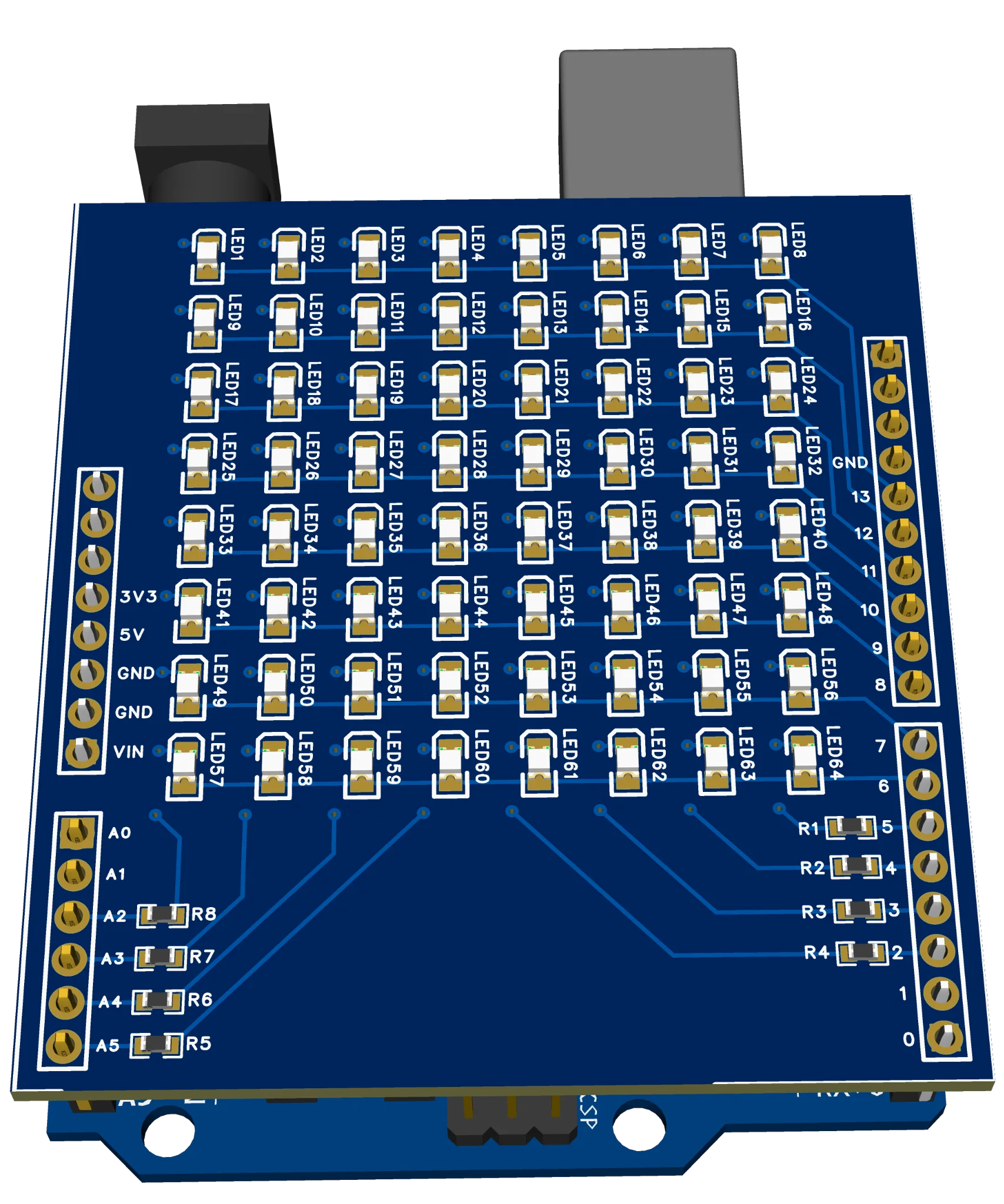
Figure: 3D rendering of a custom Arduino Uno shield PCB designed, showing clean trace routing, SMT components, and an 8x8 LED matrix.
For designs with large numbers of SMD LEDs, resistors, or driver ICs, JLCPCB also provides component sourcing and PCB assembly services. Professional SMT assembly and reflow soldering help reduce manual assembly effort while ensuring consistent manufacturing quality.
Conclusion
Direct software LED multiplexing allows small microcontrollers to control large displays using careful scan timing and shared wiring architectures. While direct GPIO matrix scanning and Charlieplexing place a high processing demand on your software, they provide an incredibly cheap, minimalist, and deeply educational way to bypass hardware pin limits.
Designing custom layouts, exporting standard Gerbers, and utilizing professional SMT fabrication services like JLCPCB's PCB Assembly ensure perfect PCB soldering and reliable display operation, taking your electronic projects to a commercial-grade finish.
FAQs about Arduino LED Multiplexing
Q: How Many LEDs Can Arduino Control Without External ICs?
Using standard direct driving, an Arduino Uno can drive roughly 15–20 LEDs. By using 16 pins in an 8x8 direct matrix scanning configuration, you can drive 64 LEDs. If you implement Charlieplexing with 18 available pins, you can theoretically drive up to 306 LEDs (18 x 17) directly.
Q: Multiplexing vs Charlieplexing: What's the Difference?
Standard row-column multiplexing uses a grid where pins are configured strictly as binary outputs (HIGH or LOW). Charlieplexing utilizes the tri-state logic of microcontroller pins, setting unused pins to INPUT (high-impedance) to isolate specific anti-parallel diode pairs, dramatically reducing the pin footprint.
Q: Do LED Matrices Need a Resistor on Every LED?
No. You only need one resistor per active line on your scanning axis (e.g., 8 resistors on the 8 column lines). This ensures that only one resistor is ever in series with any active LED at any given instant during the row sweep.
Q: Why Do Multiplexed LEDs Become Dimmer?
Because multiplexed LEDs are turned on and off sequentially, their duty cycle drops. In an 8-row scanned matrix, each LED is only active for 1/8th of the time, lowering the average current dramatically and causing it to appear slightly dimmer to the human eye.
Q: What is the Minimum Refresh Rate to Avoid Flickering?
The absolute minimum refresh rate to eliminate visible pulsing is 60 Hz. For comfortable viewing without strain, aim for a scan rate of 100 Hz or higher.
Popular Articles
• How to Create a Bluetooth-Controlled Car With Arduino: A Step-by-Step Guide
• How to Design and Assemble a Reliable ESP32 Module PCB on a 2-Layer Board
• The Ultimate Guide to Relay Symbol: Coil, Contacts, Diagrams, and Circuit Applications
• How to Identify SMD LED Polarity: Markings, Testing, and PCB Tips
• The Ultimate Guide to PCBA: Process,Types and Techniques for the Electronics Enthusiast
Keep Learning
Arduino LED Driver Tutorial: Control More LEDs with 74HC595 and MAX7219
Arduino GPIO pins run out quickly in larger LED projects. By utilizing dedicated LED drivers and expansion ICs, you can drastically reduce pin usage, eliminate processor-heavy multiplexing loops, and simplify display wiring. In this guide, you will learn the operational architecture, wiring configurations, cascading techniques, and optimization strategies for the 74HC595 shift register and the MAX7219 LED driver. Why Arduino Projects Need LED Driver ICs Arduino GPIO and Current Limitations An ATmega32......
How to Create a Bluetooth-Controlled Car With Arduino: A Step-by-Step Guide
This tutorial walks through the complete engineering and implementation of a two-wheel Bluetooth RC car with an Arduino Nano module on a specially designed PCBA (Printed Circuit Board Assembly). While many hobbyists start by wiring motors and Bluetooth modules with jumper cables on a breadboard, this approach is prone to disconnection and signal noise. This guide upgrades that process by teaching you how to design a professional mainboard. Key Design Features Controller: Arduino Nano used as a plug-in......
Fiducial Marks in PCB and SMT Assembly: A Complete Guide to Accuracy and Design Rules
Modern Printed Circuit Boards (PCBs) are complex, integrating high-density components like 0.4mm pitch Ball Grid Arrays (BGAs), 0201 passives, and fine-pitch Quad Flat No-Lead (QFN) packages. In this advanced manufacturing environment, achieving placement accuracy measured in micrometers is crucial. A significant challenge in automated manufacturing is how pick-and-place machines, which handle thousands of components per hour, precisely locate the PCB. A board on a conveyor system is never in the perf......
Alternating Current vs Direct Current (AC vs DC): What's the Difference?
Electric current flows in two primary forms: alternating current (AC) and direct current (DC). AC periodically reverses direction, while DC flows steadily in one direction. AC powers the industrial and residential electrical grids, while DC powers batteries, electric vehicles, and nearly all modern consumer electronics. Understanding the core differences between AC and DC matters when designing power supplies, selecting electronic components, or laying out printed circuit boards (PCBs). This guide com......
Arduino LED Multiplexing Tutorial: Control More LEDs with Fewer Pins
The Arduino Uno is a powerful tool for prototyping, but driving multiple LEDs directly quickly exhausts its 20 GPIO pins and its 200 mA absolute maximum package current limit. To bypass these hardware bottlenecks, engineers and hobbyists use LED multiplexing to scale display outputs efficiently without upgrading the microcontroller. In this guide, you will learn the core principles of LED matrix scanning, Charlieplexing, refresh timing, ghosting fixes, and practical Arduino code without relying on any......
Op Amp Symbol Explained: Pinout, Polarity, and Power Pins
The op amp symbol is one of the most common shapes in analog schematics: a triangle with two inputs and one output. Reading it correctly, knowing which pin is inverting, which is non-inverting, and how power connects, is the first skill needed before building any amplifier circuit. Standard op amp symbols include a non-inverting input, an inverting input, an output, and power supply connections that may be shown or hidden depending on schematic style. The common symbol convention uses a triangle with ......