
TQFP vs LQFP: Differences, Specs, Applications & Which to Choose
11 min
- TQFP vs LQFP – Key Differences Explained
- When Should You Use TQFP vs LQFP Packages?
- What Is a TQFP Package?
- What Is an LQFP Package?
- Are the TQFP Package and LQFP Package Interchangeable?
- Frequently Asked Questions
- Conclusion
Key Takeaways
Quick Selection Guide
Use the following guidelines to choose the right package for your project:
- Prototyping & Early Testing → LQFP
Easier soldering, inspection, and rework - Mass Production → TQFP
Better suited for automated assembly and compact layouts - High Pin Count Designs → LQFP
Longer leads improve yield and solder reliability - Ultra-Thin & Space-Constrained Products → TQFP
Lower profile enables slimmer device designs
The TQFP (Thin Quad Flat Package) and LQFP (Low-Profile Quad Flat Package) are two of the most common surface-mount IC packages used in modern electronics. While they share a similar quad-lead design, differences in body height, lead length, and pin pitch make them suited for distinct applications.
Understanding these differences is crucial for PCB design, soldering, and assembly. In this guide, we’ll break down TQFP vs LQFP, comparing specifications, soldering considerations, PCB layout tips, and practical use cases for engineers and designers.
TQFP vs LQFP – Key Differences Explained
TQFP (Thin Quad Flat Package) and LQFP (Low-Profile Quad Flat Package) are both quad-lead surface-mount IC packages, but they differ in key aspects such as height, lead design, pin pitch, soldering ease, and PCB compatibility.
Understanding these differences is essential for engineers when selecting the right package for your PCB design, assembly process, and overall product reliability.
| Feature | TQFP | LQFP | Implication |
|---|---|---|---|
| Package Height | 1.0–1.2 mm | 1.0–1.4 mm | LQFP slightly thicker on some models; TQFP is “ultra-thin” for very compact boards |
| Lead Design | Shorter gull-wing leads | Longer gull-wing leads | LQFP leads facilitate easier soldering and inspection; TQFP may require precise soldering |
| Pin Count | 32–176 pins | 32–208 pins | LQFP supports higher pin counts for complex ICs |
| Pin Pitch | 0.5–0.8 mm | 0.4–0.8 mm | LQFP offers finer pitch for high-density applications |
| Footprint Compatibility | Standard JEDEC/QFP land patterns | Standard JEDEC/QFP land patterns | Both can share footprints with minor adjustments |
| Soldering & Rework | More challenging, higher risk of bridging | Easier for hand soldering; better for prototyping | Choose based on assembly method and rework needs |
Package Height Comparison
The TQFP package is designed to be very thin, typically 1.0–1.2 mm, making it ideal for ultra-compact applications such as portable devices or small embedded boards.
The LQFP package, while still low-profile, usually ranges 1.0–1.4 mm, giving slightly more body height that helps reduce stress during soldering and improves handling for higher pin-count ICs.
Lead Design & Gull-Wing Leads
Both packages feature gull-wing leads, but the differences matter:
- TQFP: Shorter leads; more sensitive to soldering technique. Misalignment or excess solder can easily cause bridging.
- LQFP: Longer leads allow better solder wetting and easier inspection, reducing assembly errors and facilitating prototype hand soldering.
Lead design impacts mechanical reliability, thermal dissipation, and ease of rework, especially for dense boards.
Pin Count and Pin Pitch Differences
- TQFP: Typically 32–176 pins, standard 0.5–0.8 mm pitch. Suitable for moderate-density ICs.
- LQFP: Can go up to 208 pins, with pitches as fine as 0.4 mm. Supports higher-density designs and complex microcontrollers.
Smaller pitch requires careful stencil design and controlled reflow to avoid bridging, which is critical in high-performance boards.
Footprint Compatibility
Both TQFP and LQFP follow JEDEC and IPC standards, so their footprints are largely compatible. However, when swapping one for the other:
- Verify lead length and body dimensions
- Adjust solder mask clearance if necessary
- Ensure pad size matches thermal and mechanical requirements
This ensures reliable solder joints and prevents assembly defects.
Soldering Difficulty and Rework
- TQFP: Short leads and thin body make hand soldering difficult. Rework requires precision soldering tools or hot-air reflow.
Note
To avoid the headache of manual bridging and soldering defects, many engineers opt for JLCPCB's SMT Assembly service. With a massive in-stock parts (670,000+ components), you can have your TQFP or LQFP chips professionally mounted, ensuring high yield and saving hours of bench time.
- LQFP: Longer leads and slightly higher body make manual soldering easier, ideal for prototypes or low-volume boards. Automated assembly handles both well, but LQFP generally offers higher tolerance for process variations.
When Should You Use TQFP vs LQFP Packages?
Choosing between TQFP and LQFP depends on board space, pin count, assembly method, and design complexity. Understanding the strengths of each package helps engineers select the optimal IC package for their specific application.
Ideal Use Cases for TQFP Package
TQFP packages excel in ultra-compact and high-density applications where PCB space is limited:
- Portable electronics: Smartphones, wearables, and small IoT devices
- Embedded microcontrollers: Low-profile boards requiring minimal height
- Consumer electronics: Remote controls, compact sensors, and small modules
Key advantages: Thin profile allows slimmer designs, but shorter leads demand precise automated soldering. Manual rework is challenging, making TQFP ideal for volume production with controlled assembly.
Ideal Use Cases for LQFP Package
LQFP packages are better suited for moderate-to-high pin-count applications and prototyping:
- Microcontrollers and DSPs: Boards requiring 64–208 pins
- Automotive and industrial electronics: Durable and easier to solder
- Prototyping and small-batch production: Hand soldering or rework-friendly designs
Key advantages: Slightly higher profile and longer leads make soldering easier, reducing the risk of bridging or tombstoning. LQFP is practical for both automated and manual assembly.
Industry Examples
- TQFP: Ultra-thin MCUs in compact wearable devices
- LQFP: Automotive microcontrollers, IoT gateways, and industrial sensors
By understanding these application scenarios, engineers can match package selection to PCB layout constraints, assembly process, and reliability requirements, ensuring optimal performance and manufacturability.
What Is a TQFP Package?
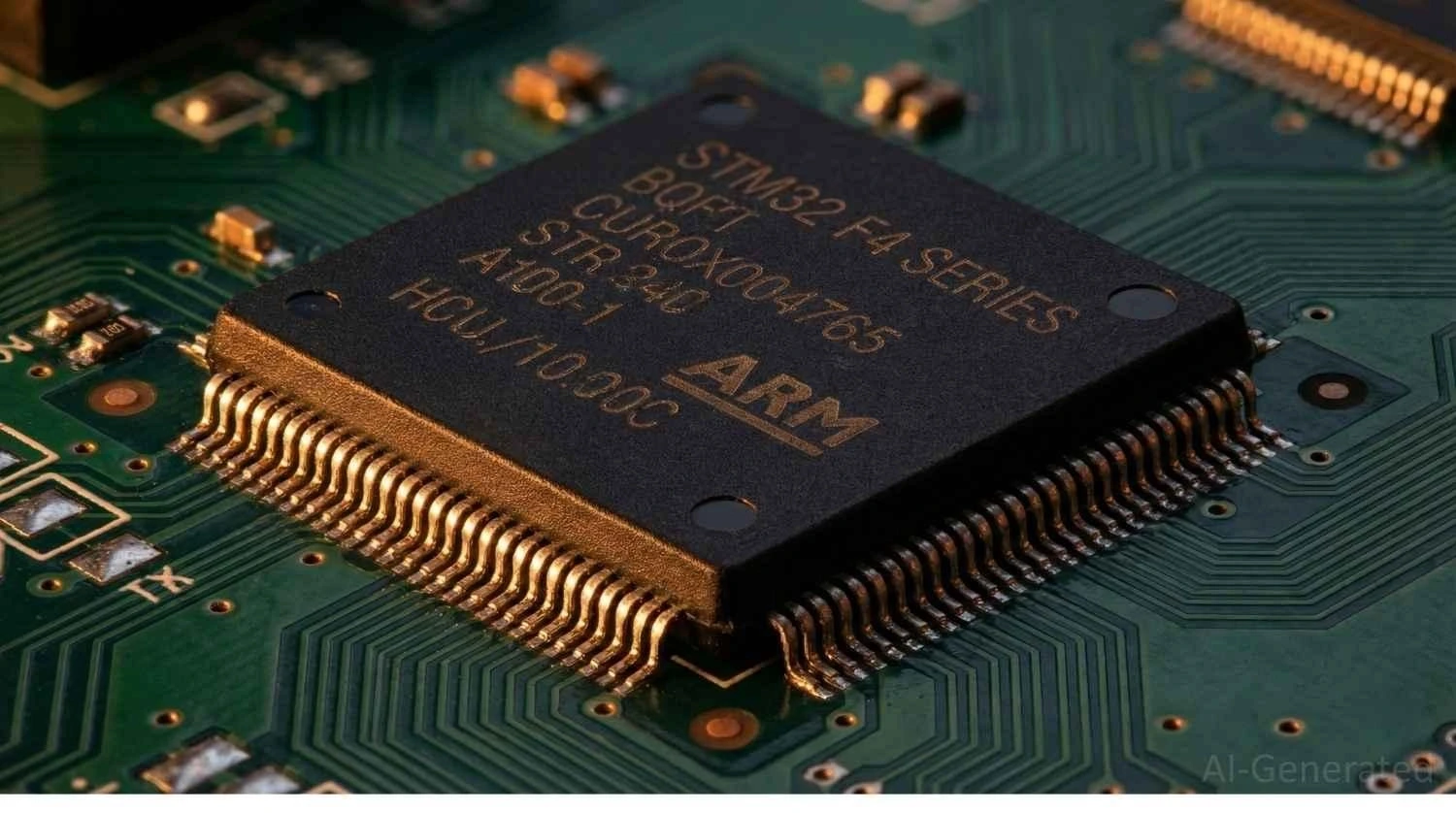
The TQFP, or Thin Quad Flat Package, is a surface-mount IC package characterized by its low-profile body and gull-wing leads extending from all four sides. Designed for high-density circuits, TQFP packages provide a compact footprint while maintaining reliable solder connections, making them ideal for space-constrained applications such as microcontrollers, DSPs, and communication ICs.
Key Features of TQFP Package
- Thin Profile: Typically 1.0–1.2 mm in height, allowing slimmer PCB designs.
- Pin Count: Commonly ranges from 32 to 176 pins, supporting a variety of IC complexities.
- Gull-Wing Leads: Extend outward and downward for easier soldering and inspection.
- Standardized Footprint: Compatible with JEDEC and IPC guidelines, ensuring broad manufacturing support.
TQFP packages are widely adopted in consumer electronics, industrial control boards, and embedded systems, offering a balance between compact design and manufacturing reliability.
What Is an LQFP Package?
The LQFP, or Low-Profile Quad Flat Package, is a surface-mount IC package designed for high pin-count applications while maintaining a slim profile. Like TQFP, it features gull-wing leads on all four sides, but its slightly lower body height and longer leads make it easier to solder and inspect, especially in prototyping and moderate-density PCB designs.
Key Features of LQFP Package
- Low Profile: Typically 1.0–1.4 mm in height, ideal for compact electronics.
- Pin Count: Available from 32 to 208 pins, accommodating complex ICs.
- Gull-Wing Leads: Extended design facilitates reliable solder joints and visual inspection.
- Standardized Dimensions: Follows JEDEC and IPC guidelines for footprint consistency.
LQFP packages are commonly used in microcontrollers, automotive electronics, communication modules, and industrial control boards, providing a practical balance between assembly ease and high-performance functionality.
Are the TQFP Package and LQFP Package Interchangeable?
In some cases, TQFP and LQFP packages may appear interchangeable because they share similar quad-lead designs and standardized footprints. However, they are not always directly replaceable, and improper substitution can lead to assembly issues, reliability problems, or even functional failure.
Before replacing one package with the other, engineers must carefully evaluate mechanical, electrical, and manufacturing factors.
Conditions for Interchangeable Use
TQFP and LQFP may be interchangeable when the following conditions are met:
- Same Pin Count and Pin Assignment: Both packages must have identical pin numbers and layouts.
- Matching Pin Pitch: The lead pitch must be exactly the same (for example, 0.5 mm or 0.8 mm).
- Compatible Body Dimensions: Package length, width, and lead length must fit the existing footprint.
- Thermal and Electrical Similarity: Power dissipation and thermal resistance should fall within acceptable limits.
If these conditions are satisfied, the two packages may share a common PCB footprint with minimal modification.
Datasheet Checks Before Replacement
Before attempting substitution, always verify the manufacturer’s datasheet. Key parameters to review include:
- Package outline drawings
- Lead length and standoff height
- Tolerance ranges
- Recommended land patterns
- Maximum reflow temperature
Small differences in tolerance or lead geometry can significantly affect solder joint quality. Relying only on nominal dimensions increases the risk of assembly defects.
Risks and Limitations
Even when TQFP and LQFP seem mechanically compatible, several risks remain:
- Soldering Issues: Shorter TQFP leads may result in insufficient solder fillets on LQFP footprints.
- Mechanical Stress: Mismatched body height can introduce stress during thermal cycling.
- Inspection Difficulty: Reduced lead exposure may complicate optical inspection.
- Yield Reduction: Minor mismatches can increase bridging, opens, or cold joints.
For high-reliability products such as automotive, medical, or industrial systems, direct replacement without redesign is strongly discouraged.
Practical Recommendation
Although limited interchangeability is sometimes possible, the safest approach is to design dedicated footprints for each package type whenever possible. When substitution is unavoidable, prototype testing, X-ray inspection, and thermal cycling validation should be performed to ensure long-term reliability.
In most professional designs, TQFP and LQFP should be treated as functionally similar but mechanically distinct packages rather than fully interchangeable components.
Frequently Asked Questions
Q: Can TQFP and LQFP use the same PCB footprint?
In some cases, TQFP and LQFP packages can share a similar footprint if their pin count, pitch, and lead length are identical. However, this is not always guaranteed. Differences in lead extension and package height may affect solder joint quality. Always verify the recommended land pattern in the manufacturer’s datasheet before using a shared footprint to avoid assembly defects and reliability issues.
Q: Is LQFP better for prototyping than TQFP?
Yes, LQFP is generally more suitable for prototyping and low-volume production. Its longer gull-wing leads and slightly higher body profile make hand soldering, inspection, and rework easier. TQFP, with shorter leads, usually requires more precise tools and experience, making it less convenient for early-stage development and manual assembly.
Q: TQFP vs LQFP: Which package is more suitable for automated assembly?
Both TQFP and LQFP are compatible with modern automated SMT assembly lines. However, TQFP is often preferred in high-volume production where precise placement and reflow control are available. LQFP offers higher process tolerance and may achieve better yields in mixed or small-batch production environments with less optimized equipment.
Q: Does package type affect signal integrity in TQFP vs LQFP?
In most standard applications, there is little to no noticeable difference in signal integrity between TQFP and LQFP packages. While minor variations in lead structure may slightly influence parasitic inductance and capacitance, these effects are generally negligible.
Q: How do I choose between TQFP and LQFP for microcontrollers?
For compact, space-constrained designs and mass production, TQFP is often the better choice. For development boards, prototypes, and designs requiring frequent rework, LQFP is usually more practical. Engineers should consider pin count, assembly method, available tools, and expected production volume before selecting the package type.
Q: Are TQFP and LQFP Packages still widely used in new designs?
Yes, both packages remain widely used in embedded systems, automotive electronics, and industrial controllers. Although newer packages such as QFN and BGA are gaining popularity, TQFP and LQFP are still favored for their inspectability, reliability, and ease of debugging, especially in professional and educational applications.
Conclusion
Both TQFP and LQFP packages provide reliable solutions for surface-mount IC applications, each serving different engineering priorities.
TQFP is optimized for ultra-thin designs and high-volume mass production, while LQFP offers greater flexibility for prototyping, high pin-count devices, and rework-friendly applications.
By matching the package type to your design and manufacturing goals, you can improve assembly yield, long-term reliability, and overall product performance.
Popular Articles
• SMD Capacitor Sizes: Complete Size Chart and Selection Tips for PCB Design and Assembly
• SMD Diode Code Lookup: Full List, Marking Guide & Identification [2026 Guide]
• SMD Resistor Package Sizes: Complete Size Chart, Footprints & How to Choose
• SMD Capacitor Codes: Identification, Markings, and Polarity
• How to Solder SMD Components Like a Pro [2026 Updated]
Keep Learning
SMD Transistor Code Lookup: Identify Markings, Pinout & Multimeter Test Guide
Repairing a circuit board often brings a familiar frustration: staring at a tiny, three-legged black component with an obscure two- or three-letter code. Whether troubleshooting a bare prototype or a mass-produced PCBA, knowing how to quickly decode these surface-mount device (SMD) markings is an essential skill for any electronics engineer or repair technician. In this comprehensive guide, you will learn: 1. How to decode SMD transistor marking codes 2. How to identify BJT vs MOSFET types 3. How to f......
SMD Capacitor Sizes: Complete Size Chart and Selection Tips for PCB Design and Assembly
In the world of modern electronics, surface mount devices (SMDs) have revolutionized board design, allowing for smaller, faster, and more efficient printed circuit boards. When designing a PCB, selecting the correct SMD capacitor sizes is one of the most critical decisions an engineer must make to ensure both electrical reliability and manufacturability. In this article, you will find practical, authoritative guidance on: Comprehensive SMD capacitor size charts for quick reference. How to read imperia......
SMD Diode Code Lookup: Full List, Marking Guide & Identification [2026 Guide]
In modern electronics, surface-mount diodes are used everywhere - from power input protection circuits to high-speed signal routing. Because these components are extremely small, manufacturers cannot print full part numbers on their bodies. Instead, they use short marking codes such as A2, M7, SS14, or SL, which often confuse beginners during PCB repair, reverse engineering, or component replacement. This guide explains how to decode SMD diode codes, identify polarity, test components using a multimet......
Thin Film vs. Thick Film Resistors: Key Differences & Selection Guide
Key Takeaways Default to thick film resistors for most designs. They are cost-effective, robust, and ideal for pull-ups, LED current-limiting, digital circuits, and surge-prone applications. Choose thin-film resistors whenever a resistor defines an analog quantity, such as a voltage divider, reference network, gain-setting circuit, or current-sensing signal chain. Their tight tolerance and low TCR help maintain measurement accuracy over temperature and time. Most PCB designs use thick film or thin fil......
Capacitor Types Explained: Applications, Differences, and Selection Guide
Capacitors are the most widely used parts in electronics design, from input/output coupling to bypassing and decoupling networks; they find applications everywhere. And if you get the wrong part/value placed, the consequences may be you get an audible whine from a supply rail, a bootloader that won't start, or a capacitor that lights up like a match. The question that never comes up is "which brand?" It's always “which type and what value.” This tutorial does not waste time on a textbook explanation o......
PoP Package (Package on Package) Explained: Architecture, Assembly, and SMT Challenges
In the race for miniaturization, fitting more processing power into smaller footprints is the ultimate challenge for PCB designers. Package on Package (PoP) technology answers this by integrating logic and memory vertically, becoming the standard for modern mobile processors. However, this 3D architecture demands advanced SMT assembly capabilities beyond standard fabrication. JLCPCB specializes in the high-precision manufacturing required to master these complex stacks. This guide covers how PoP packa......