
Rigid-Flex PCB Assembly: Design, Process, Quality & Cost
12 min
- What is Rigid-Flex PCB Assembly?
- Comparing Standard PCB Assembly, Flexible PCB Assembly, and Rigid-Flex PCB Assembly
- The Full Process of Rigid-Flex PCB Assembly
- Rigid-Flex PCB Assembly: Factors That Influence Quality, Reliability, and Cost
- Conclusion
- FAQs about Rigid-Flex PCB Assembly
Miniaturization, higher functionality, and mechanical adaptability are three main trends in modern electronics. Circuit boards that can tolerate bending, vibration, and compact or small installation spaces are becoming more and more necessary for modern devices like smartphones, medical implants, and aerospace systems.
Combining flexibility and stability, rigid-flex PCBs provide both mechanical strength and design freedom, while flexible PCBs allow for bending and folding in confined spaces.
This hybrid approach enables engineers to utilize the rigid section for component mounting and the flexible section for interconnection, creating the ideal combination that lowers the need for connectors, improves reliability, and enhances mechanical integrity under stress. As a result, Rigid-flex PCB assembly has become the fundamental component of sophisticated electronics design.
Rigid-flex PCB
What is Rigid-Flex PCB Assembly?
The process of mounting and soldering electronic components onto a printed circuit that integrates rigid and flexible layers into a single integrated structure is known as Rigid-flex PCB Assembly. The flexible Polyimide sections act as a dynamic interconnection, which enables folding, bending, or three-dimensional circuit routing; on the other hand, the rigid sections, made of FR4 or similar laminates, hold heavy and heat-sensitive components.
Unlike pure rigid or flexible PCBs, rigid-flex PCBs must manage unique challenges like thermal expansion mismatches, stress concentration at the transition areas, and accurate component alignment across various material types. This hybrid nature demands exceptional proficiency in process control and mechanical design, particularly in reflow soldering, lamination, and post-assembly handling.
The end result is a circuit that offers high mechanical durability, electrical reliability, and space efficiency- enabling the next generation of advanced, sophisticated, and compact electronic devices.
Comparing Standard PCB Assembly, Flexible PCB Assembly, and Rigid-Flex PCB Assembly
Understanding how Rigid-Flex PCB Assembly differs from standard or flexible PCB assembly is vital for knowing its advantages and complexity.
In standard PCB assembly, the entire circuit is fabricated on a rigid FR4 board. The material provides inherent stability, making it easy to print solder paste, place components, and perform reflow soldering. These boards remain perfectly flat and dimensionally stable under heat, which allows for straightforward, high-speed automated assembly. However, they are unsuitable for applications requiring mechanical bending or three-dimensional installation.
On the other hand, flexible PCB assembly presents fully different challenges. As the flexible Polyimide (PI) has poor rigidity, it is susceptible to stretching and warping under heat and pressure. In this flex PCB assembly process, the circuit must be placed onto a rigid carrier or pallet to maintain flatness. Slow, low-temperature soldering profiles and additional process control are required due to dimensional instability, thermal sensitivity, and the possibility of mechanical stress cracks. As a result, flex PCBs are perfect for extremely dynamic designs, but their assembly is difficult and costly.
Rigid-flex PCB assembly bridges these two realms. It enables smooth mechanical and electrical connectivity in small structures by combining flexible PI layers for movement and rigid FR4 areas for stability.
As the majority of the components are mounted on rigid zones during the assembly, no external carriers are required. The primary difficulty or challenge of Rigid-flex PCB assembly is controlling the thermal mismatch and stress distribution between the rigid and flexible sections. Because of the different expansion rates of FR4 and PI when heated, tension is created at the interface, which needs to be carefully reduced through slow cooling cycles and a gradual thermal ramp-up.
Consequently, the rigid-flex PCB offers both simplicity and adaptability, but at the expense of more complicated manufacturing, the need for higher precision, and specialized process handling.
The Full Process of Rigid-Flex PCB Assembly
Rigid-flex PCB assembly follows the general principles of Surface Mount Technology (SMT), but it requires advanced process preparation, precise temperature control, and strict process discipline to maintain both mechanical integrity and electrical reliability.
Phase 1: Material Preparation and Conditioning
Incoming Quality Control (IQC) and Baking
Because both rigid and flexible substrates are hygroscopic, they must be pre-baked at a controlled temperature to remove absorbed moisture before assembly. This critical step prevents delamination, blistering, or other moisture-induced defects during reflow soldering.
Surface Cleaning and Stabilization
To remove the oxidation and impurities that can cause defects when soldering, the circuit surface must be cleaned. As the flexible section can sag or warp, precision carriers or partial jigs are used to hold the flexible parts securely while leaving the rigid section accessible for component mounting.
Material Preparation and Conditioning
Phase 2: Solder Paste Printing and Component Mounting
Solder Paste Application
Solder paste is accurately printed on rigid sections where components will be mounted by using a stainless-steel stencil. The flexible parts are temporarily fixed or shielded to prevent deformation during this step.
Component Placement (Pick-and-Place)
Surface Mount Devices (SMDs) are placed accurately onto the paste by high-speed SMT machines on rigid sections. The downward pressure, the Z-axis force, of the machine is carefully calibrated to seat the component correctly, avoiding the deformation of the material. Accuracy at the micron level is ensured by vision alignment systems.
Solder Paste Printing and Component Mounting
Phase 3: Controlled Reflow Soldering
Compared to rigid PCBs, reflow soldering in Rigid-flex PCB assembly is more complex. For the prevention of mechanical failure, the hybrid board needs to be exposed to controlled temperatures.
● Gradual Temperature Ramp: To reduce the thermal shock, the heating profile starts out slowly.
● Low Peak Temperature: For the protection of Polyimide layers, the peak temperature is kept between 230 and 240°C.
● Uniform Airflow and Thermal Balancing: For the prevention of uneven heating between the rigid and flexible zones, the oven’s airflow must be optimized. This reduces the risk of delamination and warping.
● Slow Cooling Rate: The controlled cooling ensures smooth contraction between the materials.
Reflow Soldering
Phase 4: Post-Reflow and Final Rigid-Flex PCB Assembly
Attachment of Stiffeners and Connectors
Stiffeners, made of FR4 or PI, and reinforcement plates are attached close to the connectors of folding sections to strengthen critical areas. This gives the solder joints structural support during repeated bending cycles.
Through-Hole Component Assembly
Through-hole components are soldered using selective or manual methods for mixed technology designs. The controlled heat technique prevents defects and harms nearby flexible layers.
Cleaning, De-panelization, and Inspection
After the soldering parts, the assemblies go through flux cleaning and then de-panelization, where each is carefully separated from the fabrication panel. The accuracy and solder joint defects are checked by using Automated Optical Inspection (AOI) and X-ray inspection.
Electrical and Mechanical Testing
Electrical performances are verified by Flying Probe or In-Circuit Testing (ICT). Flexibility, folding endurance, and thermal cycling stability are tested via a mechanical test procedure.
Post-Reflow and Final Rigid-Flex PCB Assembly
Rigid-Flex PCB Assembly: Factors That Influence Quality, Reliability, and Cost
Technical Factors in Rigid-Flex PCB Manufacturing
1. Thermal Expansion Mismatch
As rigid boards (FR4) and flexible layers (PI) expand and contract at different rates, this difference can cause small cracks or layer separation during the soldering. To prevent this, a slow heating and cooling process is necessary during reflow so that the materials can adjust smoothly.
2. Layer Adhesion and Bonding
Because of a gap or weak bonding, the board can peel or break when it bends or heats up. All layers inside a rigid-flex PCB must stick together. So, materials must be baked to remove the moisture, and lamination should be done under vacuum pressure for proper layer bonding.
3. Transition Zone Design
The transition zone is very crucial. Sudden shape changes or sharp edges can cause cracks or damage. Hence, Rigid-Flex PCB manufacturers should design these areas with smooth curves, rounded copper traces, and gradual changes of layer thickness, which helps to spread the stress evenly.
4. Copper Thickness and Materials
As thicker copper ensures strength but provides poor flexibility, Rigid-Flex PCB manufacturers must choose the right copper thickness to balance between strength and flexibility.
Technical Factors in Rigid-Flex PCB Manufacturing
2. Quality Control & Testing in Rigid-Flex PCB Assembly
One of the most crucial aspects of rigid-flex PCB assembly is maintaining good quality. All rigid-flex PCBs must be pre-baked to remove the moisture and prevent bubbles or delamination before assembly starts. And after the soldering, AOI is used to check component position, and X-ray inspection (AXI) is used to find any hidden solder defects.
The electrical testing is done to check the connection accuracy, and through mechanical tests bending and flex quality is confirmed. In some high-end products, the boards are checked under heat and vibration to ensure their stability and reliability. These ensure the boards’ performance and safety standards.
Quality Control & Testing in Rigid-Flex PCB Assembly
3. Cost Factors in Rigid-Flex PCB Assembly
Due to the requirement of special materials, more process steps, and longer production time, rigid-flex PCB assembly costs more than a regular board. During the assembly, careful lamination of different materials and special jigs or carriers is needed to keep the board stable.
Also, controlled and well-maintained heating and cooling take more time during the reflow. On the other hand, for the inspection after soldering, advanced equipment is needed, which causes an increase in manufacturing costs.
Though the manufacturing cost is high, it is justified for the rigid-flex PCB assembly as it saves space, reduces the need for connectors and cables, and lasts longer. In various industries like the medical sector, aerospace, and automotive, reliability is more important than cost, and here rigid-flex PCBs play a vital role.
In conclusion, the cost and quality of rigid-flex PCB assembly highly depend on how well the materials are handled, bonded, and tested. Rigid-flex PCBs are ideal for high-reliability electronic devices due to their excellent mechanical stability, flexible interconnections, and long-term reliability.
Cost Factors in Rigid-Flex PCB Assembly
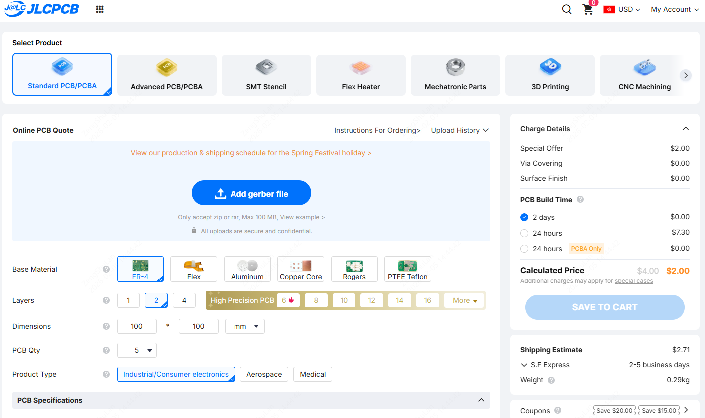
Get an Instant Quote for Your Rigid or Flex PCB Manufacturing and Assembly
Looking to manufacture or assemble your rigid PCB or flex PCB? Try JLCPCB’s online instant quoting platform — simply upload your Gerber files, choose your specifications, and receive a real-time, transparent quote within seconds. Experience how easy it is to manage your PCB manufacturing and assembly all in one place.
Note: JLCPCB currently does not support the manufacturing or assembly of rigid-flex PCBs.
Conclusion
Rigid-Flex PCB assembly represents the ideal balance of mechanical durability and design adaptability. By integrating rigid and flexible layers into a single framework, engineers can achieve exceptional electrical performance, long-term reliability, and optimized space utilization.
The result is a highly efficient circuit that maximizes layout potential, even in complex assemblies that demand meticulous control of thermal, mechanical, and lamination parameters.
FAQs about Rigid-Flex PCB Assembly
Q1: Can Components Be Mounted on Flex PCBs?
Yes, it is feasible, but usually only for lightweight, compact parts. The primary limitation is that dynamic flexing, or repeated movement, is not permitted in these areas as it would rapidly deteriorate the solder joints. To create a stable mounting point, FR4 or polyimide patches are frequently used to locally stiffen flexible areas where components must be placed.
Q2: How Many Bending Cycles Can a Rigid-Flex PCB Handle?
The rating depends on the application.
Static Flex: The circuit is capable of lasting the whole operational lifespan of the device, which is millions of cycles without crashing, so long as the flex section has been bent just once through installation and undergoes minimal dynamic stress.
Dynamic Flex: The board is usually manufactured to endure 10,000–500,000 full bends in design, which are in perpetual motion. Engineers deliberately use thinner copper and route traces to mitigate stress through flexing to achieve higher cycle counts.
Q3: What Is the Minimum Bend Radius for Flex PCBs?
The flexible stack-up's thickness and layer count determine the minimum safe radius. The radius for a single flexible layer can be as little as three to five times the thickness of the material. To avoid excessive strain and cracking in the outer copper traces, the radius for multi-layer flexible sections must be much larger, usually 6 to 10 times the total thickness.
Q4: How Are Rigid and Flex Layers Aligned During Lamination?
A high-precision tooling and registration system ensures accurate alignment between the flexible and rigid layers before lamination. Tight-tolerance tooling holes are drilled through all layers—including polyimide, copper, FR4, and adhesive—to maintain layer-to-layer registration. Each stack is mechanically aligned and secured on tooling pins immediately prior to the heat and pressure bonding cycle, minimizing layer shift during lamination.
Q5: Are Flexible PCBs Suitable for High-Speed Signals?
Flexible traces impose electrical limitations:
● Power/Current: Due to their limited ability to transfer heat via thin dielectric layers, flexible conductors have less capacity to carry current. Broader trace geometries should be deployed by designers to minimize heat buildup as well as ensure consistency.
● Impedance Control: As they don’t have a solid ground plane, it’s challenging to keep the signal impedance constant in flexible PCBs, which may lead to signal loss or distortion, particularly at higher frequencies.
Popular Articles
• Common PCB Assembly Methods and Soldering Techniques Explained
• What Is BGA Void? Causes, IPC Limits, and Solutions
• SMD Soldering Tools You Need: Complete Guide from Beginner to Pro
• Reflow Soldering: Everything You Need to Know
• SMT Assembly Process Explained and Equipment Used: A Step-by-Step Guide to PCBA Manufacturing
Keep Learning
Common PCB Assembly Methods and Soldering Techniques Explained
Whether you're designing your first prototype or scaling up to production, understanding PCB assembly methods and soldering techniques is crucial to achieving reliable, high-performance circuit boards. Modern PCBA primarily relies on Surface Mount Technology (SMT) and Through-Hole Technology (THT)—each offering unique advantages for component density, durability, and manufacturability. In this guide, we'll break down the major PCB assembly methods, key soldering techniques such as reflow and wave sold......
12 Professional Soldering Tips and Tricks Every Beginner Should Know
Soldering is not merely "gluing" metal; it is a metallurgical process that creates an intermetallic compound (IMC). This molecular bond ensures the electrical and mechanical integrity of your device. A poor joint might pass a quick visual check but will inevitably fail under vibration or thermal stress, leading to "ghost" bugs and hardware failures. These soldering tips and tricks focus on practical, repeatable techniques used in professional electronics soldering—from correct heat transfer and flux u......
Solder Melting Point Guide: Chart, Alloy Types, and Reflow Considerations
In the precise world of electronics manufacturing, a difference of just a few degrees can mean the distinction between a perfect, reliable solder joint and a catastrophic "cold" joint failure. While many hobbyists view soldering simply as "melting metal to stick things together," professional PCB assembly requires a nuanced understanding of thermodynamics. The solder melting point is not simply a single value listed in a datasheet; it is a decisive limit that determines the choice of components, the s......
The Ultimate Guide to Solder Flux: Everything You Should Know Before Soldering PCB
Soldering is needed to make almost all electronic devices. Adding solder alone won't make a joint that is strong, clean, and sound from a metallurgical point of view. Solder flux is a very important part of the process that comes in here. If you want to do your job better and make it more reliable, you need to know a lot about soldering flux, whether you're an engineer, a professional technician, or just a hobbyist. This article goes into a lot of detail about solder flux, including what it is, how it......
Flex PCB Assembly Guide: Process, Challenges, and Solutions
Flexible Printed Circuit Boards (Flex PCBs) are the foundational technology enabling the compact, innovative design of modern electronics. Because of their ability to bend and fold, they power devices from smart wearables to compact medical instruments where traditional rigid printed circuit boards (Rigid PCBs) can't be used. Achieving a functional electronic circuit from the raw plastic film demands special expertise, with flexible PCB assembly (FPCA) representing the crucial final step in this trans......
SMD Rework Guide: Tools, Temperatures, and Techniques That Prevent PCB Damage
From replacing a burned regulator to correcting wrong component values or removing solder bridges on fine-pitch ICs, SMD rework is an essential skill in electronics manufacturing and prototyping. It allows engineers to repair assembly defects, implement design changes, and recover valuable PCBs without the cost and delay of building new boards. In this guide, you will learn: What SMD rework is Common rework scenarios Tools and temperatures Safe removal and installation Package-specific techniques Real......